Water Specialties TR28-2 User manual

30119-41 Rev. 1.6/02-07
1
DIGITAL
INDICATOR - TOTALIZER
TRANSMITTER
MODEL TR28-2
OPERATION AND MAINTENANCE MANUAL
PARTS LIST
FEATURING:
*MODEL CN08-2 DIGITAL INDICATOR-TOTALIZER
*ENCAPSULATED ELECTRONICS
*SOLID STATE CONSTRUCTION
*CURRENT OUTPUT SIGNAL
*PULSE OUTPUT SIGNAL
*SEALED HOUSING
3255 WEST STETSON AVENUE
HEMET, CALIFORNIA 92545 U.S.A.
PHONE:
FAX:
VISIT OUR WEBSITE:
951-652-6811
951-652-3078
www.mccrometer.com

30119-41 Rev. 1.6/02-07
2
WARRANTY
This Warranty shall apply to and be limited to the original purchaser consumer of any McCrometer
product. Meters or instruments defective because of faulty material or workmanship will be
repaired or replaced, at the option of McCrometer, free of charge, FOB the factory in Hemet,
California, within a period of one (1) year from the date of delivery.
Repairs or modifications by others than McCrometer or their authorized representatives shall
render this Warranty null and void in the event that factory examination reveals that such repair
or modification was detrimental to the meter or instrument. Any deviations from the factory
calibration require notification in writing to McCrometer of such recalibrations or this Warranty
shall be voided.
In case of a claim under this Warranty, the claimant is instructed to contact McCrometer, 3255
W. Stetson Ave., Hemet, California 92545, and to provide an identification or description of the
meter or instrument, the date of delivery, and the nature of the problem.
The Warranty provided above is the only Warranty made by McCrometer with respect to its
products or any parts thereof and is made expressly in lieu of any other warranties, by course of
dealing, usages of trade or otherwise, expressed or implied, including but not limited to any
implied warranties of fitness for any particular purpose or of merchantability under the uniform
commercial code. It is agreed this Warranty is in lieu of and buyer hereby waives all other warran-
ties, guarantees or liabilities arising by law or otherwise. Seller shall not incur any other obliga-
tions or liabilities or be liable to buyer, or any customer of buyer for any anticipated or lost profits,
incidental or consequential damages, or any other losses or expenses incurred by reason of the
purchase, installation, repair, use or misuse by buyer or third parties of its products (including any
parts repaired or replaced); and seller does not authorize any person to assume for seller any other
liability in connection with the products or parts thereof. This Warranty cannot be extended,
altered or varied except by a written instrument signed by seller and buyer.
This Warranty gives you specific legal rights, and you may also have other rights which vary from
state to state.
McCrometer reserves the right to make improvements and repairs on product components which
are beyond the Warranty period at the manufacturer’s option and expense, without obligation to
renew the expired Warranty on the components or on the entire unit. Due to the rapid advance-
ment of meter design technology, McCrometer reserves the right to make improvements in design
and material without prior notice to the trade.
All sales and all agreements in relation to sales shall be deemed made at the manufacturer’s place
of business in Hemet, California and any dispute arising from any sale or agreement shall be
interpreted under the laws of the State of California.
Copyright © 2005 McCrometer. All written material should not be changed or altered without permission of McCrometer.
The published technical data and instructions is subject to change without notice. Contact your McCrometer representative for current technical data and instructions.

30119-41 Rev. 1.6/02-07
3
MODEL TR28-2
DIGITAL INDICATOR-TOTALIZER-TRANSMITTER
INDEX
I. DESCRIPTION
II. SPECIFICATIONS
III. UNPACKING
IV. INSTALLATION
V. METERS
1. Remove
2. Clean Meter Head
3. Transmitter Mounting Base
4. Postition of Indicator-Totalizer-Transmitter
5. Transmitter Wiring
VI. OPERATION AND MAINTENANCE MANUAL
VII. PRINCIPALS OF OPERATION
1. TR28-2 Functions
2. Battery
3. Power to TR28-2
VIII. SENSOR and TR28-2 DIGITAL
INDICATOR-TOTALIZER-TRANSMITTER
1. TR28-2 Digital Transmitter
2. TR28-2
3. Sensor Assembly
4. Battery Replacement
IX. TROUBLESHOOTING
1. Troubleshooting Guide
2. Working Area
3. TR28-2 Digital Transmitter
4. Moisture
5. Transmitter Communication Lines
6. TR28-2 Circuit
X. INSPECTION
XI. REASSEMBLY
XII. INOPERATIVE INSTRUMENT EVALUATION
1. Check All Instruments and Transmitters
2. Check Your Instrument
3. Transmitter or Communication Line
4. Full Scale Output
5. Transmitter Communication Lines
6. Communications Problems
7. Separation of Signal and Power
I. DESCRIPTION:
The Model TR28-2 Digital Indicator Totalizer
Transmitter provides flow rate indication, totalization
of flow volume and a current output signal proportional
to the rate of flow when mounted on our meters. The
TR28-2 is for installation on propeller meters.
II. SPECIFICATIONS:
ACCURACY Rate
±0.25% of reading.
TEMPERATURE
Operation: 32° to 160° F.
RANGE
Storage: -40° to 160° F.
Consult factory for special construction for other
temperatures.
INPUT SIGNAL
Type: Voltage pulse.
Voltage Range: 1 to 10V.
Minimum Frequency: 0.125Hz.
Maximum Frequency: 3KHz.
Minimum Pulse Width: 2μs.
OUTPUT SIGNALS
Combination 4-20mA Output and
Isolated Scaled Pulse Output:
Standard 2 wire loop powered.
16 bits resolution.
Operating voltage: 12 to 32 VDC.
Power Switch: Auto battery override.
Scaled Pulse Output:
Open collector MOS transistor.
Pulse width: 32 milliseconds.
Maximum Rating: 1 to 32 V.
EMI/EMC
Electrostatic Discharge:
8KV
(IEC 1000-4-2 Level 3).
Electrical Fast Transient:
1KV
(IEC 1000-4-4 Level 3).
RF Susceptibility:
150 KHz to 230 MHz @ 10V
(IEC 1000-4-4 Level 3).
POWER SUPPLY
24 VDC (as supplied by our power supply Model
IN36-1, available separately) wired in series.
The Indicator-totalizer-transmitter is primarily
loop powered, but becomes self-powered via a
lithium battery in the event of a power loss.
Battery Type - 3 VDC Lithium,
Replaceable
Operating Life - 2 years (when used
with the display timeout into sleep mode
feature).
Low Battery Indication - 6 months before
expiration.
OPTIONAL
Mounting brackets, with up to 100 feet
EQUIPMENT
of cable for remote installation.
SHIPPING WEIGHT
4 pounds.
ORDERING INFO
Must be specified by the customer and includes
serial number of meter on which unit is to be
mounted, maximum scale range required for 4-20
output, indicator scale and units, totalizer dial
units. Consult factory for special applications.

30119-41 Rev. 1.6/02-07
4
III. UNPACKING. When unpacking the transmitter, any
damage due to rough or improper handling should be
reported to the transportation firm and McCrometer. If
for any reason it is determined that the unit or parts of
the unit should be returned to the factory, please con-
tact McCrometer for clearance prior to shipment. Each
unit must be properly packaged to prevent any further
damage. The factory assumes no responsibility for
equipment damaged in return shipment due to improper
packaging. Proper paperwork must be enclosed with
any returned material.
The shipping carton contains the following items:
Model TR28-2 ........................................ 1
Mounting Base O-ring ............................ 1
Mounting Base (w/hardware) ................ 1
Operation and Maintenance Manual ...... 1
IV. INSTALLATION of transmitters is normally done at the
factory when the meter is assembled, but may be made
in the field. Depending upon what situation exists,
various steps for installation apply and the procedures
are outlined below.
V. METERS with mechanical drive totalizers or indicator-
totalizers require a conversion kit. This kit consists of
all necessary parts to convert a mechanical drive meter
into an electronic meter. Follow the instructions in-
cluded with the conversion kit for your meter. Once
conversion is complete, follow the procedures outlined
below for installation of Model TR28-2 on an electronic
meter.
1. REMOVE the existing digital indicator by removing
the four mounting screws. Lift the unit slightly, turn it
over, and disconnect the two lead sensor from the bot-
tom of the indicator.
2. CLEAN METER HEAD of all dirt, glue, gaskets
and, other foreign material.
3. TRANSMITTER MOUNTING BASE (#10) and O-
ring (#12) must be installed on the meter head. Position
the mounting base (#10) so the watertight connector
(#14) and transmitter output cable (#13) are on right
side of meter when looking upstream. Apply a small
amount of silicone grease to the O-ring (#12). Secure
base to meter with four mounting screws (#11). Con-
nect the sensor wires from the meter to the bottom of
the TR28-2. Be sure terminals are secure. The sensor
wires should pass through the hole in the base cup (#8).
(See wiring diagrams on page 10 or 11.)
4. POSITION OF INDICATOR-TOTALIZER TRANS-
MITTER on top of the mounting base can be made in
one of four directions for the easiest possible reading.
Normally the units are attached so that they can be
read when looking upstream. Prior to mounting the
transmitter on the mounting base, the wiring connec-
tions must be made to the transmitter. Connect the
wire from the transmitter output cable (#13) to the mA
output terminal on the bottom of the unit. The output
is polarized. Be sure terminal is secure. DO NOT TOUCH
ANY OF THE OTHER TERMINALS ON THE BOTTOM OF
THE TRANSMITTER. Apply a small amount of silicone
grease to the base cup O-ring (#2) and secure transmit-
ter bonnet with four mounting screws (#3).
5. TRANSMITTER WIRING can be accomplished by
following the wiring diagram on page 8, 10 or 11.
TRANSMITTER
OPERATION AND MAINTENANCE MANUAL
VI. MCCROMETER products have been carefully designed
to be as maintenance-free as possible. Periodic preven-
tive maintenance, however, is highly recommended and
should be practiced according to schedule to ensure con-
tinuous accuracy and trouble-free performance of your
meter. The maintenance and inspection procedure can
also be used as a guide to locating a problem in the
transmitter that may be the cause of abnormal opera-
tion.
NOTE: METER DISPLAY WILL SHUT OFF AFTER A
FEW MINUTES WITH THE LID OPEN. TO READ
METER, CLOSE LID AND OPEN IT AGAIN.
VII. PRINCIPALS OF OPERATION
1. The Model TR28-2 has four separate functions:
1. A 4-20 mA output signal operated through
the 24 VDC loop power from the instrument.
2. Digital display rate of flow going through the
meter.
3. Digital display of total flow that has gone
through the meter from when first installed.
4. Scaled Pulse output of one pulse per totalizer
count.
2. A battery is built into the Model TR28-2 as a
backup for the rate and totalizer only in case of a
power failure. It should be understood how this
backup battery operates when the 24 VDC loop power
is off:
1. The 4-20 mA signal stops.
2. The digital rate and totalizer display stays on
until it goes into programmed sleep mode.
(See
Programming Guide, Literature #30110-17.)
3. Because the unit has a built in EEPROM
memory, the totalizer will still be storing totalizer
information even though it is not displayed.
3. When the power comes back on, the Model
TR28-2 will:
1. Send a 4-20 mA signal to the instrument
when flow starts.
2. It will display flow rate on the Model
TR28-2 when lid is opened.
3. It has been storing all quantity going through
the meter and will display totalizer by opening lid.
VIII. SENSOR AND TR28-2 DIGITAL INDICATOR-
TOTALIZER-TRANSMITTER
1. TR28-2 DIGITAL TRANSMITTER (#4) should not
be removed from the meter unless battery or sensor
replacement is required or if the unit is to be repro-
grammed. If the unit must be removed, proceed as
follows:
2. TR28-2 (#4) can be removed from the transmitter
mounting base (#10) by removing the four bonnet
mounting screws (#3).

30119-41 Rev. 1.6/02-07
5
REPROGRAMMING: The bonnet can be lifted enough
to slide the base cup and digital transmitter out of the
bonnet, allowing access to the programming buttons.
(See Programming Guide, Literature #30110-17.)
3. SENSOR ASSEMBLY in the meter can be re-
placed by following the meter instruction manual.
4. BATTERY REPLACEMENT (#6): The 3 Volt
Lithium Battery is used as a backup to the 24 VDC loop
power. In the event of a power loss, the battery will
continue to operate the rate and total functions of the
TR28-2. The “low battery” indication will appear ap-
proximately 6 months prior to expiration.
A. The bonnet (#1) can be lifted enough to ac-
cess the terminals connected to sensor input and trans-
mitter pulse/mA output.
B. Carefully disconnect the wires from the
transmitter. The unit can then be turned over and the
battery can be accessed through the opening in the
bottom of the base cup. Be sure to install the new
battery with the positive (+) and negative (-) terminals
positioned properly.
C. Reconnect the wires to the transmitter. (See
page 9.)
D. Reinsert the TR28-2 (#4) into the bonnet as-
sembly (#1) with the top of dial aligned with the
hinge side of the bonnet.
E. Install the bonnet O-ring (#2) into bonnet
with a coating of silicone grease.
NOTE: Batteries should be disposed of in an envi-
ronmentally sound manner.
IX. TROUBLESHOOTING the transmitter is necessary if it
is apparent that the instrument being controlled by the
transmitter is not receiving a proper signal from the
transmitter, and/or the totalizer or indicator-totalizer is
not functioning. Before beginning, it is important to be
sure that the problem is with the transmitter.
The following checks should be made:
1) Check to be sure that water is flowing through the
meter at flows above the minimum flow rate for the
given size meter.
2) Check the instrument to be sure it has the required
power being supplied to it.
3) Check the junction box to be sure the communica-
tion lines from the transmitter to the instrument are
making good contact and that the transmitter is wired
properly to the instrument. (See wiring diagrams on
page 8, 10 or 11.)
1. THE TROUBLESHOOTING GUIDE is provided to
help isolate any problem that may occur with the trans-
mitter. Follow the instructions and test procedures
listed for each problem.
NOTE: The meter assembly should be inspected
thoroughly to be sure it is operating properly and is not
the cause of the problem. (Refer to your meter service
manual for instruction on inspection of the meter.)
A. If the meter indicator-totalizer does work, but
the remote instrument does not operate (not receiving
proper signal), and if the 24 VDC loop power to the
Model TR28-2 is now on, then use troubleshooting pro-
cedures 2, 3, 5, 6, X, XI and XII.
B. If the meter indicator-totalizer and remote in-
strument do not operate, check the TR28-2 by opening
and closing the lid twice. If no response, then follow all
procedures.
2. WORKING AREA chosen for testing and inspec-
tion of the internal components should be clean to re-
duce the chance of dust or dirt particles being intro-
duced into the transmitter mechanism.
3. TR28-2 DIGITAL TRANSMITTER must be re-
moved from the mounting base (#10) to gain access to
the transmitter terminals and to check connections.
Remove the unit from the mounting base following in-
structions in section VIII. Check the connection from
the sensor in the meter to the terminals in the bottom
of the TR28-2. Check the connection from the pulse
and mA terminals on the TR28-2 to the instrument.
Make sure the connection is clean and tight, and that
the terminal is secure.
4. MOISTURE should not be apparent within the
transmitter bonnet (#1). All O-rings should be inspected
for breaks or presence of foreign materials that allow
leakage to occur. Check to be sure water is not coming
up through the meter head. If water is coming up
through the meter head then the meter should be
checked. (See meter service manual.)
5. TRANSMITTER COMMUNICATION LINES (#13)
should be checked to determine the current level flow-
ing in the loop. The method of measurement is to insert
a multimeter into the 4-20 mA loop by disconnecting
one of the mA signal wires, clipping one side of multi-
meter to disconnected wire and connecting other end of
multi-meter to the lug or post from which the wire was
removed.
A. If no water is flowing through the meter,
the current level should be 4.0 mA. The purpose of the
4.0 mA at no flow is to ensure that the loop is com-
plete. If there is 4.0 mA in the loop when no water is
flowing, then the loop is intact.
B. If water is flowing through the meter, the
current level should be between 4 and 20 mA, depend-
ing on flow.
6. TR28-2 CIRCUIT should be checked to be sure it
is functioning properly. The circuit may be checked as
follows:
A. If the current level in the loop is 0.0 mA,
check the voltage between the mA terminals at the
transmitter. It should be at the maximum power supply
level (± 1.0 VDC).
If there is no voltage present, then check the loop
voltage at its source. If there is voltage at the voltage
source, then there is an opening in the loop.
If there is no voltage at the power supply, discon-
nect loop and check supply by itself. If the voltage level
is still 0 VDC or very low (<10 VDC), replace power
supply.
B. If the level of current is greater than 20 mA,
there are two possibilities. The TR28-2 may be starting
to fail, but unless there has been some major damage
done to the unit (physical impact or voltage levels above

30119-41 Rev. 1.6/02-07
6
50 VDC applied), it should not exceed 21.00 mA.
High loop current can also be caused by a short in
the transmitter hookup cable. A zero Ohm short will
cause power supply fuse to blow. However, it is pos-
sible to have a shunt of about 0.5W to 10W connecting
transmitter lines, which will cause excessive loop cur-
rent with transmitter in system (from 70.0 - 350 mA or
more), but when TR28-2 is tested separately it works
fine. These shorts are difficult to find. They can be
caused by incorrect wiring installation or damage to
wiring. Damage can be caused by physical contact
(back hoe, etc.) or from environmental effects (water in
the raceways).
C. If transmitter output remains at 4.0 mA even
when the meter and sensor are operating properly, the
TR28-2 must be replaced.
If the loop current is within a satisfactory range,
3.90 mA to 21.00 mA, and varies with a varying flow
rate, but is not showing desired values, the unit can be
programmed with different totalizer, rate scale, zero mA
value, and full scale mA value. (See Programming Guide,
Literature #30110-17.)
X. INSPECTION and field testing has been accomplished
at this point. Should any of the parts, upon inspection,
appear to be damaged, they must be replaced to ensure
proper operation and prevent further damage.
XI. REASSEMBLY is necessary at this point. Before reas-
sembling, make certain that the unit is cleaned of any
dust or dirt. Costs for replacement parts not covered
by warranty are available by contacting the factory.
BEFORE RETURNING TRANSMITTER TO FACTORY,
please notify McCrometer. Each unit must be properly
packaged to prevent damage to the product during ship-
ment. Should any of the unit's parts, upon inspection,
appear to be damaged, they must be replaced to ensure
proper operation and prevent further damage. Costs for
replacement parts not covered by warranty are avail-
able from current parts and price list. Should the unit
require further inspection, it must be reassembled and
returned to the factory.
XII. PROCEDURES FOR CHECKING OUT
INOPERATIVE INSTRUMENT SYSTEMS:
Each instrument is factory-tested with the transmitter
that will be operating it. When an instrument doesn't
operate and is connected to its proper transmitter, cer-
tain procedures need to be followed to determine where
and what the problem is. Most troubleshooting proce-
dures are part of each instrument and transmitter ser-
vice manual, but these suggestions may help.
1. CHECK ALL INSTRUMENTS AND TRANSMIT-
TERS for obvious visual damage. Make certain any
necessary grounding has been made.
2. CHECK YOUR INSTRUMENT to be sure it is op-
erating properly by following the instrument service
manual. Check to be sure your instrument is operating
correctly when a simulated signal is put into it.
WARNING: Circuit to transmitter must be disconnected
when most testing equipment is used for checking your
instrument. If instrument checks out, proceed with
checking transmitter and communication lines.
3. WHEN THE TRANSMISSION OR COMMUNICA-
TION LINE is suspected of being the reason the system
is not functioning, it is usually easier to check the trans-
mitter first to be sure it is giving proper output. There
are some easy troubleshooting techniques for checking
mA output. First, you must know what mA signal is
expected from the transmitter.
A. Model TR28-2 current transmitter has
an output of 4 to 20 mA at maximum scale of the
instrument it operates.
B. The original purchaser of the equipment
should have invoices or other paperwork to confirm
what the 4 to 20 scale is. If not, contact the factory
with the meter serial number and the factory will pro-
vide the full scale information.
C. Let us assume you found the meter was
a 12" meter and the full scale of the instrument is
3,000 GPM.
4. FULL SCALE OUTPUT. Once the output at full
scale has been determined, we need find out what the
unit is measuring at.
A. Time the transmitter totalizer with a
stopwatch for 3 to 5 minutes, to give the best resolu-
tion or closest accuracy.
B. The example meter has a 1,000 gallon
totalizer and, if you time the totalizer for three counts
in 150 seconds, proceed as follows:
150 sec ÷ 3 = 50 sec for 1,000 gallons (1 count)
C. To find the true flow rate:
60 sec ÷ number of sec per count x totalizer dial
(or as shown below)
60 ÷ 50 x 1,000 = 1,200 GPM true flow rate
Now verify the indicator is accurate.
D. To determine what output the transmit-
ter should be sending, we must now find what percent
1,200 GPM is of the 3,000 GPM scale stated earlier.
1,200 GPM ÷ 3,000 GPM = 40%
Because 4 mA equals ZERO it must be subtracted from
20 mA.
Therefore, 20 - 4 = 16 mA usable output (SPAN)
40% x 16 mA = 6.4 mA then add 4 mA back to give
10.4 mA @ 1,200 GPM.
E. The 4-20 mA current signal can be
checked by using a digital multimeter. Have the multi-
meter set to measure milliamps. With no water flowing
through the meter, the ammeter should measure 4.0
mA. If water is flowing through the meter, the current
level should be between 4 to 20 mA.
NOTE: A.C. power should be removed from circuit be-
fore inserting the multimeter. The multimeter must be
connected in series with circuit being tested.
5. TRANSMITTER COMMUNICATION LINES (#13)
should be checked to determine if the pulse output is
present.
WARNING: A.C. power should be disconnected to the
instrument prior to any work taking place on the wiring.

30119-41 Rev. 1.6/02-07
7
A. The preferred method of checking the
pulse output is to use a McCrometer Model IN16 at-
tached to the pulse output of the TR28-2. The
McCrometer IN16 will count each time the transmitter
sends a pulse.
B. A voltmeter can also be used to check
the pulse output. Using a voltmeter, on 0 to 5 VDC
scale, measure voltage between the two pulse output
wires when the totalizer count changes. It will display
a pulse voltage every time the totalizer counts. (The
voltage displayed will depend on how quickly your meter
responds.)
If the pulse is present at the instrument, then the prob-
lem is with the instrument. If the pulse is not present,
perform the same tests at the junction box and at the
transmitter itself. If the pulse is present at the junction
box, then the problem is with the communication lines
from the junction box to the instrument. If the pulse is
present at the transmitter, there is something wrong in
the communication lines between the transmitter and
the instrument. If no pulse can be measured, the unit
must be returned to the factory. (See section XI, 1.)
6. COMMUNICATION PROBLEMS can be so com-
plex it is usually recommended the instrument contrac-
tor or electrical contractor be informed that our trans-
mitters and indicators prove to be good units and the
trouble could be elsewhere. Sometimes it is necessary
to lay another line from the transmitter to instrument
above ground to help prove the lines are at fault prior
to pulling and replacing existing line. Communications
lines should be kept from tangling up in high voltage
lines inside the panel or wiring cabinet. Communication
lines should be shielded cable and not run in same con-
duit as power lines. Sometimes the 115 V A.C. line
used for the instrument can be causing the trouble. It
is suggested the plug from the instrument be tempo-
rarily transferred to another A.C. outlet which is on
another circuit. It has been found a fluorescent light
circuit tied in with the instrument power source, or
faulty parking lot vapor lights can affect the instru-
ments if A.C. wiring is done incorrectly, giving a noisy
A.C. circuit. Make certain the ground is connected to
earth ground.
7. SEPARATION OF SIGNAL AND POWER wiring
in separate conduits is the traditional precaution; how-
ever, other measures must be taken to minimize the
effects of electromagnetic interference (EMI) and radio
frequency interference (RFI) on the operation of the
instrument. Otherwise, if high level, short duration noise
spikes are permitted to enter the digital equipment, the
noise can be transferred into the systems logic net-
works and can be misinterpreted as signal data, result-
ing in erroneous system operation and other unpredict-
able responses. Potential noise sources:
Relay coils
Solenoids
AC power wires
Current carrying cables
Radio frequency transmissions
30119-41 Rev. 1.6/02-07
8
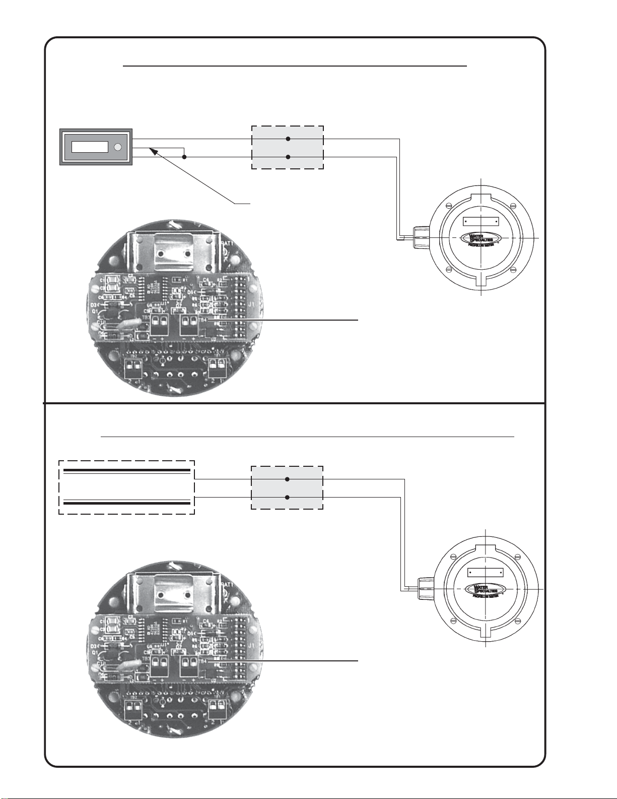
JUNCTION BOX
AUXILIARY EQUIPMENT
WHITE (+)
BLACK (
-
)
0
JUNCTION BOX
MODEL IN16
REMOTE TOTALIZER
RESET WIRE (IF DESIRED)
(SEE IN16 DATA SHEET)
WHITE (+)
BLACK (
-
)
WHITE (+)
BLACK (
-
)
PULSE OUTPUT WIRING WHEN USED WITH AUXILIARY EQUIPMENT
PULSE OUTPUT WIRING WHEN USED WITH MODEL IN16
MODEL TR28-2
MODEL TR28-2
Isolated Pulse
Output
Left Pin Right Pin
Black (-) White (+)
Isolated Pulse
Output
Left Pin Right Pin
Black (-) White (+)
X
W
X
W

30119-41 Rev. 1.6/02-07
9
MODEL TR28-2
INDICATOR - TOTALIZER - TRANSMITTER
SOLID STATE CONSTRUCTION CURRENT OUTPUT PULSE OUTPUT SIGNAL
ONE PULSE PER TOTALIZER COUNT DIGITAL DISPLAYS
5
9
/
16
"
8
15
/
16
"
TR28-2 SIDE VIEW
NOTES:
The transmitter will drive up to a maximum of 600 ohms loop
resistance.
Wire Size Information:
The distance of the communication line from transmitter to the
device the 4-20mA will operate depends on the loop resistance, the
wire size, and the power supply. Based on a 24V DC power supply
and 22 gauge wire, we recommend a maximum loop of 3,500 feet.
(not used)
4-20 mA Output
Left Pin Right Pin
Green (-) Red (+)
Sensor Wiring Input
Left Pin Right Pin
Red (+) Black (-)
Power Power Supply Maximum
Supply Voltage Resistance of
for Loop Instruments in Loop
Variable 15.0VDC 150ΩΩ
ΩΩ
Ω
Variable 18.0VDC 300ΩΩ
ΩΩ
Ω
Variable 21.0VDC 450ΩΩ
ΩΩ
Ω
IN36-1(24V) 24.0VDC 600ΩΩ
ΩΩ
Ω
Variable 27.0VDC 750ΩΩ
ΩΩ
Ω
Variable 30.0VDC 900ΩΩ
ΩΩ
Ω
SHIELD TO PLAIN EARTH
GROUND AT PANEL END
RED (+) AND GREEN (-)
4-20 mA (LOOP POWERED)
BLACK (-) AND WHITE (+)
FOR PULSE OUTPUT
(ONE CONTACT PER
TOTALIZER COUNT)
Isolated Pulse
Output
Left Pin Right Pin
Black (-) White (+)
X
W
X
W
W
X
W
X
30119-41 Rev. 1.6/02-07
10
ANALOG OUT
INPUT
RESET INPUT
GROUND
12 VOLT OUT
DC POWER IN
ISOLATE -12V
ISOLATE +12V
A.C. IN
A.C. IN
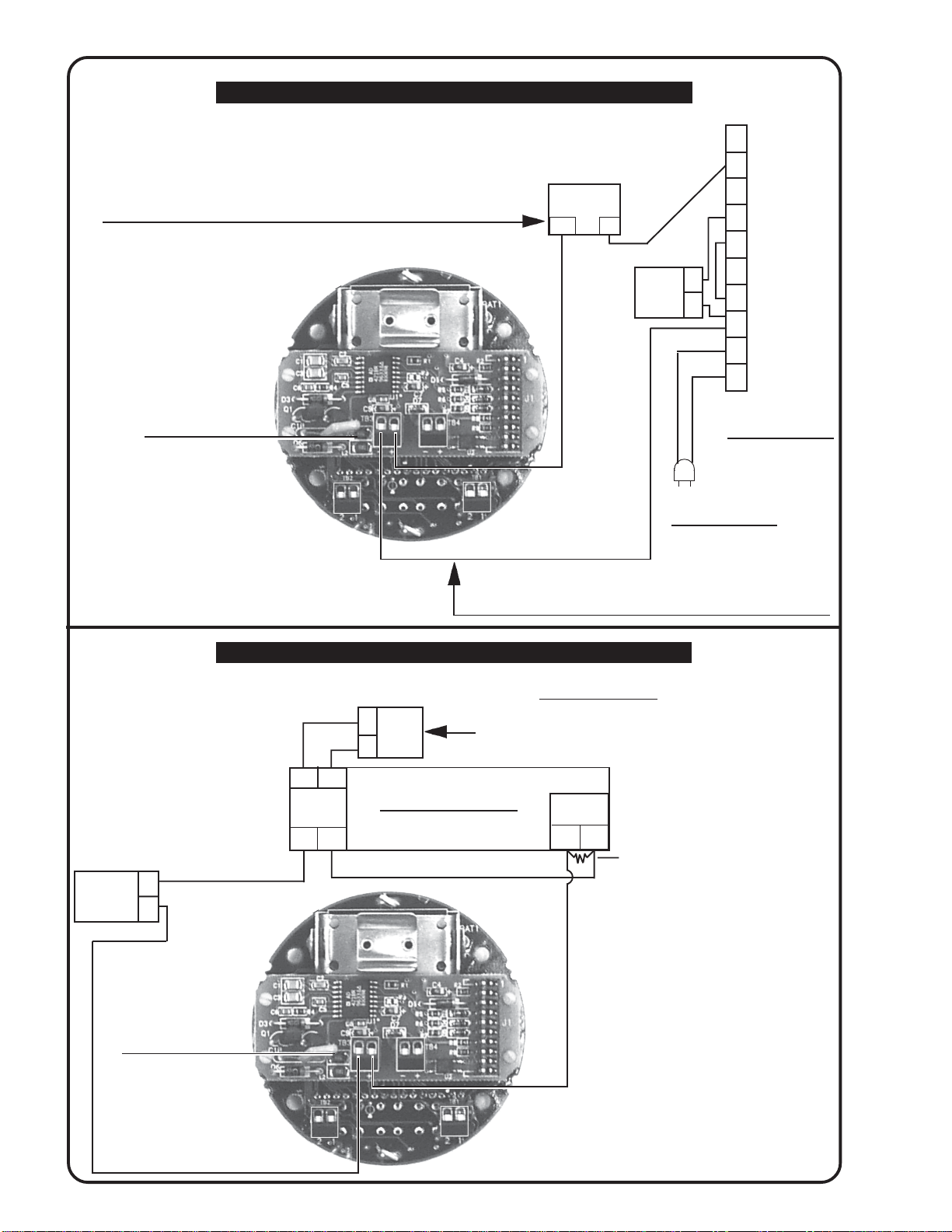
NOTE: Connections for measuring the amount of current flowing in the 4-20 mA loop.
There should be 4.0 mA with no water flowing through meter and 20.0 mA at full scale.
Connect ammeter in series with circuit.
110 VAC / 60 HZ
TO INSTRUMENT
IN60
TERMINAL STRIP
NOTE: Connections for checking power supply voltage for the transmitter.
(24 VDC) connect voltmeter in parallel with circuit.
RED
TESTING TRANSMITTER OUTPUT AND POWER SUPPLY VOLTAGE
TR28-2 TRANSMITTER (4-20 mA OUTPUT)
WIRED TO A MODEL IN60
GREEN
-
+
4-20 mA
AMMETER
TESTING TRANSMITTER OUTPUT AND POWER SUPPLY VOLTAGE
TR28-2 TRANSMITTER (4-20 mA OUTPUT)
WIRED TO A MODEL IN48 12" CHART RECORDER SOLD BEFORE 05/93
250 OHM RESISTOR
JUMPER
RED
GREEN
AMMETER
4-20 mA +
-
NOTE: Connections for checking transmitter power supply voltage (24 VDC).
Connect voltmeter in parallel with circuit.
TRANSMITTER POWER
(24 VDC)
NOTE: Connections for measuring the amount of
current flowing in the 4-20 mA loop. There should
be 4.0 mA with no water flowing through meter
and 20.0 mA at full scale. Connect ammeter in
series with circuit. If there is no current in the
loop and the power supply voltage is there, then
the problem is possibly in the communication lines
or the transmitter circuit board.
NOTE: TRANSMITTER CABLE
SHIELD TO GROUND.
NOTE: TRANSMITTER CABLE
SHIELD TO GROUND.
3
4
5
12
13
14
15
16
17
18
+
-
VOLT
METER
(24 VDC)
4-20 mA Output
Left Pin Right Pin
Green (-) Red (+)
+
IN48 TERMINAL STRIP
+
-
J-10
+
-
4-20 mA INPUT
J-6
+
-
VOLT
METER
+
-
4-20 mA Output
Left Pin Right Pin
Green (-) Red (+)
W
X
W
X

30119-41 Rev. 1.6/02-07
11
WIRING DIAGRAM FOR TR28-2 TO IN41
TR28-2 TRANSMITTER (4-20 mA OUTPUT)
WIRED TO A MODEL IN41 10" CHART RECORDER
WIRING DIAGRAM FOR TR28-2 TO IN48
FOR RECORDERS SOLD AFTER 05/93
FROM TRANSMITTER RECEIVING POWER FROM RECORDER
NOTE: TRANSMITTER
CABLE SHIELD TO GROUND.
JUMPER
GREEN
+
J2 PLUG
4-20 mA
J11 PLUG
TRANSMITTER POWER
(24 VDC)
+
-
-
4-20 mA Output
Left Pin Right Pin
Green (-) Red (+)
+
-
TB-2
GREEN
RED
Isolated Pulse
Output
Left Pin Right Pin
Black (-) White (+)
RED
4-20 mA Output
Left Pin Right Pin
Green (-) Red (+)
Isolated Pulse
Output
Left Pin Right Pin
Black (-) White (+)
NOTE: TRANSMITTER
CABLE SHIELD TO GROUND.
W
X
W
X
X
W
X
W
RECORDER
MAIN PCB
24 VDC
POWER SUPPLY
V+ V-
30119-41 Rev. 1.6/02-07
12
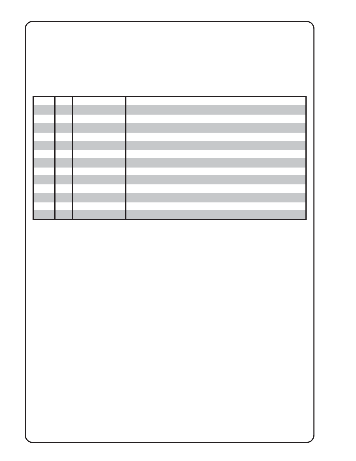
When ordering replacement parts, please specify: • Meter Size •Meter Model •Meter Serial Number
Contact Factory For Pricing.
DIGITAL INDICATOR - TOTALIZER - TRANSMITTER
MODEL TR28-2
PARTS LIST
Part Number
5-4316-D-2
1-1551-38
1-1115-10-10B
5-TR28-2
3-1910-28-2
1-1783-8
1-4318-5
1-1551-17
4-4141-1
1-1115-10-10B
1-1551-18
3-1701-4
1-1711-5
No.
1
2
3
4
5
6
8
9
10
11
12
13
14
Description
Digital Indicator-Totalizer Bonnet Assembly
O-ring, Digital Indicator-Totalizer Bonnet
Screw, Bonnet Mounting (each)
Digital Indicator-Totalizer Assembly (Items 5 to 9)
Digital Indicator Totalizer
Battery (each)
Base Cup
O-ring, Base Cup
Base Assembly
Screw, Bonnet Mounting (each)
O-ring, Mounting Base
Cable Assembly, 4 lead
Water Tight Connector
QTY
1
1
4
1
1
1
1
1
1
4
1
1
1

30119-41 Rev. 1.6/02-07
13
DIGITAL INDICATOR - TOTALIZER - TRANSMITTER
MODEL TR28-2
FOR ELECTRONIC PROPELLER METERS
Table of contents


