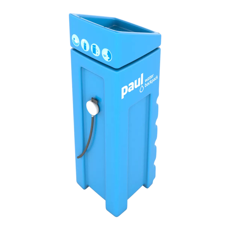
WaterBackpack PAUL User manual

PAUL®station manual page i
PAUL Station Manual 2019-08-02 www.waterbackpack.org 02.08.2019
Content
1Principle of the PAUL®Station ....................................................1
2What can be delivered for the PAUL®Station............................3
2.1 Overview..............................................................................................3
2.2 Upgrading an existing PAUL®standard unit.....................................4
3Before the assembly.....................................................................5
3.1 Considerations on the raw water source ..........................................5
3.2 Water supply for the Raw Water Tank ............................................... 5
3.3 Overview over available accessories for the PAUL®station ........... 6
3.4 Necessary tools...................................................................................6
3.5 Scope of delivery ................................................................................ 7
3.6 Height of the tanks relative to the PAUL®unit.................................. 8
4Assembly.......................................................................................9
4.1 Set 1 to connect the Raw Water Tank with PAUL®........................... 9
4.1.1 Overview ....................................................................................9
4.1.2 Mounting the tank connector on the Raw Water Tank................9
4.1.3 Connecting the Raw Water Tank with PAUL®...........................12
4.1.4 Remarks on the OPV or OPV-S ...............................................12
4.2 Set 2 to connect PAUL®with the Filtered Water Tank....................14
4.2.1 Overview .................................................................................. 14
4.2.2 How to install............................................................................14
4.3 Set 3 outlet FWT................................................................................ 16
4.4 Set 4 side outlet with hose ............................................................... 17
4.5 Overfill Protection Switch (OPS) for the Raw Water Tank.............. 19
4.6 Run-Dry Protection Switch (RPS) .................................................... 19
5Start-up and operation ...............................................................20
5.1 OPV adjustment ................................................................................ 20
5.2 Start-up of the PAUL®station........................................................... 21
5.3 Temporary stop of operation............................................................ 22
6Maintenance................................................................................23
6.1 Daily................................................................................................... 23
6.1.1 Water level inside PAUL®.........................................................23

page ii PAUL®station manual
PAUL Station Manual 2019-08-02 www.waterbackpack.org 02.08.2019
6.1.2 Sieve between RWT and PAUL®..............................................23
6.2 Weekly................................................................................................23
6.2.1 Removing slurry from the PAUL®unit .......................................23
6.2.2 Measurement of maximum filtration capacity ............................24
6.3 Monthly...............................................................................................25
6.3.1 Cleaning of the FWT.................................................................25
6.4 Undefined frequency.........................................................................26
6.4.1 Cleaning the RWT.....................................................................26
6.4.2 Cleaning the membrane module...............................................26
7Troubleshooting..........................................................................27
7.1 Waterlevel in PAUL®is too low.........................................................27
7.2 How to disassemble and re-assemble PAUL®.................................27
8Additional information................................................................32
8.1 Chlorine dosing .................................................................................32
8.2 Taking PAUL®out of operation for a long period of time...............33
9Detailed list of parts that come with set 1 to set 4...................34

PAUL®station manual page iii
PAUL Station Manual 2019-08-02 www.waterbackpack.org 02.08.2019
List of figures
Figure 1: Scheme of the PAUL®station .........................................................1
Figure 2: requirements concerning height of tanks and PAUL®unit ................8
Figure 3: All parts that come with set 1 and how to connect............................9
Figure 4: RWT connector parts of set1 (top: ¾" version, down: 1“ version)
pre-assembled................................................................................10
Figure 5: RWT connector parts of set1 (top: ¾" version, down: 1“ version)
ready for mounting in the RWT....................................................... 11
Figure 6: RWT connector parts of set1 (top: ¾" version, down: 1“ version)
ready for mounting in the RWT....................................................... 11
Figure 7: LWS box.........................................................................................13
Figure 8: All parts that come with set 2 including water meter (left) and float
valve for the FWT (right) and how to connect.................................14
Figure 9: Connection between PAUL®and the Filtered Water Tank –
installation scheme.........................................................................15
Figure 10: Connection between PAUL®and the Filtered Water Tank (set 2)
– what comes with PAUL®and how to mount the water meter.......15
Figure 11: Set 3 consisting of trank connector and ball tap .............................16
Figure 12: Side outlet with hose ......................................................................18
Figure 13: OPV for PAUL®..............................................................................20
Figure 14: OPV with rotated float arm (transport position)...............................21
Figure 15: OPV correct adjusted .....................................................................21
Figure 16: meter reading.................................................................................24
Figure 17: sample protocol for maximum filtration test.....................................25
Figure 18: membrane module – look through the slits between the plates ......31

page iv PAUL®station manual
PAUL Station Manual 2019-08-02 www.waterbackpack.org 02.08.2019
List of tables
Table 1: List of parts included in set 1: connection between RWT and
PAUL®(RWT connection with ¾" diameter)....................................34
Table 2: List of parts included in set 1: connection between RWT and
PAUL®(RWT connection with 1" diameter).....................................35
Table 3: List of parts included in set 2: connection between PAUL®and
FWT................................................................................................35
Table 4: List of parts included in set 3: outlet FWT........................................36
Table 5: List of parts included in set 4: side outlet with hose.........................36

PAUL®station manual page 1
PAUL Station Manual 2019-08-02 www.waterbackpack.org 02.08.2019
1 Principle of the PAUL®Station
The waterbackpack PAUL®is the core of the PAUL®station. The basic idea
behind it is that it is essential to be able to tap large amounts of water in a short
time. As the filtration process in PAUL®is steady but slow, two additional tank
are necessary:
a Raw Water Tank (RWT) that stores the raw water so PAUL®can filter
continuously
a Filtered Water Tank (FWT) to store the filtered water during times where
no water is tapped
Figure 1 shows a scheme of the PAUL®Station arrangement.
Figure 1: Scheme of the PAUL®station

page 2PAUL®station manual
PAUL Station Manual 2019-08-02 www.waterbackpack.org 02.08.2019
Water is pumped into the RWT (as an example, in the scheme above realized
with a solar powered solution) and flows into the PAUL®unit. The filtered water
from the PAUL®unit then flows into the FWT.
As a consequence, all three units have to be equipped with installations that
prevent overfilling in order to allow fully unattended use.
This automatic overfilling prevention for the whole PAUL®station is realized
by the following tools (see also Figure 1):
in the RWT: the OPS, i.e. Overfill Protection Switch, an electrical switch in
a float is used that switches off the electrical raw water pump if the water-
level exceeds an adjustable level
in the PAUL®unit: the OPV, i.e. Overfill Protection Valve (also called "auto-
stop valve") is used that closes the inlet if the waterlevel in PAUL®exceeds
a certain height
in the FWT: the FV, i.e. Float Valve (also called "auto-stop valve") is used
that closes the inlet to the FWT if the water level in the FWT exceeds an
adjustable level
Another thing that is necessary in most situations is the RPS, i.e. the Run-dry
Protection Switch for the electric pump. The device itself is identical with the
OPS.

PAUL®station manual page 3
PAUL Station Manual 2019-08-02 www.waterbackpack.org 02.08.2019
2 What can be delivered for the PAUL®Station
2.1 Overview
The minimum scope of delivery for a permanent water supply solution by the
PAUL®station consists of
PAUL®unit equipped with
OPV (Overfill Protection Valve) which replaces the standard sieve of
PAUL®
This is the minimum requirement for a permanent water supply with the
PAUL®station, as it enables the connection between the RWT (or any
other water supply connection) with PAUL®and a self-closing cover which
can be opened in order to fill PAUL®with a bucket alternatively. Here a
sieve is provided identical to the standard sieve.
In addition to this minimum scope of delivery, the following items are available
and recommended, depending upon the local circumstances:
set 1: connecting the RWT to PAUL
set 2: connecting PAUL®to the FWT
set 3: outlet of the FWT
set 4: side outlet with hose
OPS
RPS
With the side outlet with hose, you can observe the water level inside PAUL®,
as the hose is transparent. This is sufficient in most cases.
For those, however, who want/need an automated warning once the water level
inside PAUL®is low, we offer a PAUL®control unit which consists of
OPV-S (Overfill Protection Valve with Sensor) which replaces the standard
sieve of PAUL®, including the nozzle to connect the RWT with PAUL®and
a self-closing cover which can be opened in order to fill PAUL®with a
bucket alternatively. Here a sieve is provided identical to the standard
sieve.
It is identical with the OPV but also has the water level sensor mounted.

page 4PAUL®station manual
PAUL Station Manual 2019-08-02 www.waterbackpack.org 02.08.2019
LWS (Low waterlevel Warning System) box: this separate box is con-
nected to the water level sensor mounted on the OPV-S via a 2-wire elec-
tric connection. The LWS box can be mounted close to PAUL®or even far
remote by simply adding more wiring (regardless of polarity), e.g. in the
house of the caretaker.
Although we recommend to solve the issue of water supply locally, see chapter
3.2, on special request we can also provide
12 V DC pump and
the matching solar panel
Please note: If you ordered PAUL®together with the parts needed for the
PAUL®station configuration, some items are already mounted on your PAUL®
unit.
2.2 Upgrading an existing PAUL®standard unit
If you upgrade an existing PAUL®standard unit, simply exchange the sieve and
mount the OPV (or the OPV-S) instead by removing the two screws that hold
the sieve, and then mount the OPV/OPV-S in this place by using the same
screws.

PAUL®station manual page 5
PAUL Station Manual 2019-08-02 www.waterbackpack.org 02.08.2019
3 Before the assembly
3.1 Considerations on the raw water source
In general, it is recommended to use the best available water source. PAUL®is
not able to desalinate or detox salty or toxic waters, as is also mentioned on the
device.
Thus, which water can be used?
Usually, stored rainwater, e.g. in cisterns or reservoirs is the best raw wa-
ter source, as there is little or no contamination from industry, farming or
geogenic origin.
Also, rivers can be a good source, provided there is no influence of industry
or farming upstream
If – usually due to lack of water in sufficient quantity – wells have to be
drilkled, this water may also be of very good quality. However, it is a mini-
mum requirement to check concerning heavy metals, arsenic and fluoride,
at least as a grab sample. Also the concentration on iron and manganese
should be analyzed.
Advice can be given upon request.
3.2 Water supply for the Raw Water Tank
It has to be considered how the RWT can be fed with raw water. This will usu-
ally be done by an electric pump. Energy might be supplied by local grid or by
solar power. Of course, the pump must fit to the type of energy supply.
Whatever solution is appropriate and feasible under the local circumstances, it
should be assured that filling the RWT can operate fully unattended without
overfilling the RWT.
In case of electric pumps, a float switch that breaks the electric circuit for the
pump when exceeding a set water level in the RWT can also be provided, the
so called OPS, see chapter 2.
When selecting the pump, important criteria include
Suction or submerged pump

page 6PAUL®station manual
PAUL Station Manual 2019-08-02 www.waterbackpack.org 02.08.2019
Energy requirement, depending upon length and diameter of hoses and
height to be sucked/pumped
Ability of permanent operation
Ability of running dry – if not, a Run-dry Protection Switch (RPS) is neces-
sary, see chapter 2
3.3 Overview over available accessories for the PAUL®station
In this manual, the assembly of a PAUL®station is described, basing on all ac-
cessories mentioned in chapter 2. Also, important hints are given. Of course,
except PAUL®and the OPV, everything can also be purchased locally, provided
it has the same functionality. However, we assess as follows:
Set 1: essential
Set 2: essential
Set 3: recommended
Set 4: essential
OPS: recommended (if an electric/solar pump is involved)
RPS: dependent upon your chosen pumping solution
3.4 Necessary tools
Screw-wrench AF 17, 22, 25, 30 and 32
Hose cutter, alternatively stable scissor or cutter or knife
Crimping tool, alternatively gripper
Centre bit ¾“ or 1" and ½“
Standard set of screwdrivers and phillips screwdrivers
Drilling machine is recommended

PAUL®station manual page 7
PAUL Station Manual 2019-08-02 www.waterbackpack.org 02.08.2019
3.5 Scope of delivery
This varies of course depending upon order.
However, in chapter 9 all single parts are listed an specified, so it is a good idea
to first check the delivery for completeness. If any doubts, please contact us via
Mail. Please include photos to explain your issue.

page 8PAUL®station manual
PAUL Station Manual 2019-08-02 www.waterbackpack.org 02.08.2019
3.6 Height of the tanks relative to the PAUL®unit
Before assembling the PAUL®station, it is essential to determine the exact
three-dimensional position of all three tanks, i.e. the RWT, PAUL®and the
FWT, to assure that all connections between the tanks fit and fulfil specific re-
strictions and the hoses are long enough.
The only requirement concerning positioning is that we recommend minimum
distances in height, as can be seen from Figure 2.
Figure 2: requirements concerning height of tanks and PAUL®unit
Please note that increasing the height difference between the bottom of PAUL®
and the inlet into the FWT will increase the transmembrane pressure TMP. This
results in higher flow, but it also might speed up pore blocking in the membrane,
so please do not use this simple possibility to increase water production to a
large extent.
> 0.50 m
*1
> 0.50 m
*3
*1: This can best be more than 0.50 m, as
this will assure that influent flow into PAUL
will always be sufficient high.
Note: if the height difference is very high,
(> 10 m estimated), then the OPV (part of
the PCU) must be the „high pressure“
version –please indicate when ordering!
*2: The bottom of the PAUL unit should at
least be 15 to 20 cm higher than the inlet
into the FWT (in no case lower than the inlet
into the FWT).
*3: water cans must fit under the taps.
Note: delivery flow can be increased by
adding a local pipe/hose system and placing
the taps as low as possible beneath the FWT
bottom.
*2

PAUL®station manual page 9
PAUL Station Manual 2019-08-02 www.waterbackpack.org 02.08.2019
4 Assembly
4.1 Set 1 to connect the Raw Water Tank with PAUL®
4.1.1 Overview
Figure 3 shows how to connect all parts that come with set 1.
Figure 3: All parts that come with set 1 and how to connect
On the left hand side the RWT connector can be seen. This connector comes
pre-assembled as can be seen in Figure 3.
Determine where to mount the filter. As this filter must be checked and – if
necessary – cleaned, see chapter 6.1.2, choose a location where the filter is
easily accessible, see also chapter 4.1.3. The valve is necessary to stop the
water flow during filter cleaning, so the valve should be mounted close to the fil-
ter.
Connect the RWT connector with the valve and then with the filter using the
blue hose.
Finally, connect the filter with the OPV or OPV-S mounted in PAUL®using the
blue hose.
4.1.2 Mounting the tank connector on the Raw Water Tank
It might be a good idea to execute this step before you put the RWT in place.
Figure 4 shows the two versions of RWT connector. Due to the different diame-
ter, each complete connector consists of different parts as can be seen from the
figures and the list of parts in chapter 9.
The wall of the RWT must be between the two seals.

page 10 PAUL®station manual
PAUL Station Manual 2019-08-02 www.waterbackpack.org 02.08.2019
As the connector comes pre-assembled, it has to be divided according to Figure
5.
Then, drill a hole in the RWT using the centre bit ¾“ or 1", depending upon your
tank connection diameter.
Figure 4: RWT connector parts of set1 (top: ¾" version, down: 1“ version) pre-
assembled
Note: In raw water, even if filterd at the pump inlet, there will be settleable solids. They will
accumulate at the bottom of the RWT. Thus, it is recommended to place the RWT
connector a little higher above the bottom of the RWT, as is shown qualitative in Fig-
ure 2, depending upon solids content in the raw water etc.
Also, the RWT should have a bottom outlet at the very lowest point of the tank to en-
able flushing out solids from time to time.
Although you are free to chose your most convenient way of mounting, we rec-
ommend the following steps depending upon the diameter of the connector:

PAUL®station manual page 11
PAUL Station Manual 2019-08-02 www.waterbackpack.org 02.08.2019
¾" version:
Divide the pre-assembled connector as can be seen in Figure 5:
Figure 5: RWT connector parts of set1 (top: ¾" version, down: 1“ version) ready for
mounting in the RWT
Make sure the threaded pipe with external thread is firmly screwed into the
threaded pipe with internal thread which also holds the filter cage on the other
side. Then place one of the seal on the threaded pipe with external thread, as
can be seen from the left side of Figure 5
From inside the tank, push this left part of the connector together with the seal
on the threaded pipe with external thread to the outer as far as possible.
Add the second seal on the threaded pipe with external thread.
Then tighten the connector with the counter nut on the threaded pipe, holding
tight the inner part of the connector.
Finally, screw the hose nozzle with cap nut on the threaded pipe.
1" version:
Divide the pre-assembled connector as can be seen in Figure 6.
Figure 6: RWT connector parts of set1 (top: ¾" version, down: 1“ version) ready for
mounting in the RWT
1
2

page 12 PAUL®station manual
PAUL Station Manual 2019-08-02 www.waterbackpack.org 02.08.2019
From outside the tank, push the right part of the connector as can be seen from
Figure 6together with one seal and the counter nut into the drilled hole.
Then, from inside the tank, screw the left part of the connector, i.e. the filter
cage with the pipe coupling (internal thread) on the threaded pipe. Do not forget
the second seal. To do so, use the pipe coupling to tighten the whole connec-
tion. The counter nut must be loos in this situation.
Finally, whilst still holding up the inner part of the connector, firmly tighten the
connector to the wall of the RWT with the counter nut .
Be careful when putting the RWT in place and do not damage the connector.
4.1.3 Connecting the Raw Water Tank with PAUL®
Now you can connect the RWT with the PAUL®unit, and thus carefully decide
where to cut the hose, regarding the following issues:
the water filter has to be placed horizontal with the sieve facing downward,
see Figure 3
please regard the direction of flowthrough the water filter
we recommend to place the valve close to the water filter
we recommend to place both valve and water filter close to the PAUL®unit
as this will ease maintenance (i.e. cleaning the filter from time to time, see
chapter 6)
The hose clamps have to be fixed with a crimping tool or a gripper. They cannot
be used multiple.
Please clean the RWT before you use it for the first time.
4.1.4 Remarks on the OPV or OPV-S
Usually the OPV/OPV-S is already mounted on PAUL®so you can directly start
assembly and use the hose nozzle of the OPV/OPV-S.
But if you upgrade an existing PAUL®, then you will first have to remove the
standard sieve on top of PAUL®.
Instead, mount the OPV or OPV-S in the place the standard sieve has been; it
might be a good idea to store the sieve in a safe place.

PAUL®station manual page 13
PAUL Station Manual 2019-08-02 www.waterbackpack.org 02.08.2019
Fixing the OPV or OPV-S with the two screws is very important as otherwise the
OPV or OPV-S in total will float when the water level is rising, and thus will not
prevent PAUL®from overfilling.
The OPV-S is equipped with a water level sensor that indicates if the water level
falls below a certain limit. This water level assures that a long term standstill is
possible. The sensor in the OPV-S must be connected by a very simple two line
wire. At delivery, the connector is attached to the sensor cable, and this connec-
tor has to be plugged into the LWS box that can be seen in Figure 7.
Figure 7: LWS box
If desired (which might be the case in many situations), the wire can easily be
extended to the desired length,. e.g. by placing the LWS box in a nearby flat
etc.
The LWS operates with 4 AA batteries. If no warning is issued, there is no cur-
rent, which means that the batteries last as long as their official lifetime is. Of
course you can also use AA rechargeable batteries. In order to save battery
power due to unwanted conditions during transportation, the test knob is cov-
ered with a plastic cap. If you need to replace the batteries, open the LWS (4
screws) and remove this plastic, insert new batteries/recharged batteries and
close the box again and tighten the 4 screws properly.
Then check functionality of the LWS box itself by pressing the blue knob (see
Figure 7, right hand side) – a LED light should appear and a sound should be

page 14 PAUL®station manual
PAUL Station Manual 2019-08-02 www.waterbackpack.org 02.08.2019
heard. Please check from time to time and replace/recharge batteries if needed,
see below.
To check the functionality of the whole LWS system, connect the LWS box to
the OPV-S at a low water level inside PAUL®– LED and beep should indicate
low water condition. After reaching a certain height in PAUL®, the alarm will go
off. Of course it can also be switched off by unplugging the sensor cable from
the LWS box, but do not forget to reconnect it after PAUL®is filled up again.
4.2 Set 2 to connect PAUL®with the Filtered Water Tank
4.2.1 Overview
Figure 8 shows how to connect all parts that come with set 2.
Figure 8: All parts that come with set 2 including water meter (left) and float valve
for the FWT (right) and how to connect
It is recommended to first put PAUL®and the FWT in place before cutting the
hose that connects PAUL®into the necessary pieces. Also, the requirements
explained hereafter have to be considered.
4.2.2 How to install
The standard PAUL®unit comes with a white-blue drinking water hose that
ends with a valve.
From this valve, a hose connection to the water meter must be made using the
white-blue hose, see Figure 9 and Figure 10.
Other manuals for PAUL
1
Table of contents
Other WaterBackpack Water Filtration System manuals
Popular Water Filtration System manuals by other brands

Trigano
Trigano J-PSC064 Instruction and maintenance manual

amiad
amiad Filtomat MG112 Installation, operation and maintenance instructions

Oase
Oase BioSmart 5000 operating instructions

GE
GE RPWF use and care manual

Flexco
Flexco PLY 130 WB Safety and operation manual

Apec Water
Apec Water ROES-UV75 Installation instructions & owner's manual