WaterClinic LOTUS-72 User manual

Innovation has a name.
LOTUS-72
Cabinet Reverse Osmosis User Manual
Kabinetli Ters Osmoz Kullanma Kılavuzu


ENG 1
Dear customer,
Thank you for purchasing a "Waterclinic by A.O. Smith" branded water purier!
You are now the owner of water treatment equipment produced by the world’s leading
manufacturer of water treatment systems. This equipment produces pure water that can
be consumed directly, providing you with a cleaner and healthier source of drinking water.
Please read this user manual carefully before you install and operate your
"Waterclinic by A.O. Smith" branded water purier. To achieve maximum efciency this user
manual provides detailed instructions regarding the installation of your water purier as
well as information related to the proper operation and maintenance.
The installation should only be handled by professionals authorized by A.O. Smith
Su Teknolojileri A.Ş.
Spare parts used for maintenance and replacement lters should be approved
by A.O. Smith Su Teknolojileri A.Ş. before they are installed.
Any degradation of performance caused by the use of spare parts or lters that have not
been approved by A.O. Smith Su Teknolojileri A.Ş. will not be covered by our warranty.
If you experience any difculties during installation or operation, please contact your local
distributor to have them carry out repairs or maintenance on your equipment.

ENG 2
CONTENTS
İÇİNDEKİLER

ENG
SAFETY CONSIDERATIONS 4
PRODUCT DESCRIPTION 7
Brief Introduction 7
Description of Components 7
Electrical Diagram 8
Water Route Map 8
Technical Specications 9
Functions of Main Components 9
Functions of Accessories 10
TRANSPORTATION 10
INSTALLATION METHODS 10
Pre-Installation Preparations 10
Instructions to Quick Fitting 11
Instructions for Proper Installation 12
Installation Notes 15
ADJUSTMENT METHODS 15
OPERATION WARNINGS 16
MAINTENANCE AND REPAIR 16
Filter Replacement Intervals 16
Filter Replacement Methods 17
Warnings 17
Notes 18
PACKING LIST 18
AFTER-SALES SERVICE 19
TROUBLESHOOTING GUIDE 20
TR
24
ÜRÜN TANITIMI 27
Kısa Tanıtım 27
Su Arıtma Cihazının Ayrıntılı Proli 27
Elektrik Şeması 28
Su Akış Şeması 28
Teknik Bilgiler 29
Ana Bileşenlerin İşlevleri 29
Aksesuarların İşlevleri 30
30
30
Kurulum İçin Ön Hazırlık 30
Quick Fittings Bağlantı Elemanları 31
Doğru Kurulum için Uyulması Gereken Talimatlar 32
Kurulum Uyarıları 35
35
KULLANIM UYARILARI 36
BAKIM VE ONARIM 36
Filtre Değişim Aralıkları 36
Filtre Değişim Yöntemleri 37
Uyarılar 37
Notlar 38
38
39
40
42
BAKIM KARTI 41 - 43
MONTAJ KONTROL KARTI 44
45
ENG 4
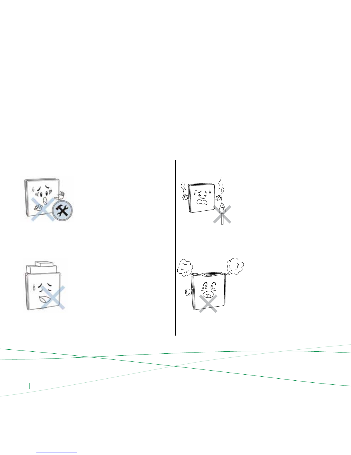
Do not disassemble or modify this water
purier on your own!
Unauthorized disassembly or modication
of the machine could lead to machine
malfunctions or leakage accidents. Please
check with the store where you purchased
this product for product consultation in order
to arrange for repairs.
Do not put the water purier close
to a source of ame!
Do not put the water purier near a source
of ame or a place where the temperature
is too high as this may cause deformation,
causing damage or leakage, which could lead
to serious personal and property damage.
Do not put heavy objects on the water
purier!
Placing heavy objects on the water purier
may cause damage to the water purier’s
external cover or internal components, which
in turn could lead to leakage, equipment
malfunctions or even serious property
damage.
Do not place any objects on top of your
water purier!
Obstructing the heat dissipation may lead to
machine damage or res.
Warnings
Please read carefully and take into consideration the following notications. Otherwise, it may cause permanent damage to your equipment or cause
serious property damage.
Safety Considerations
(Be sure to read and remember these safety considerations)
Make note of the following safety precautions In order to avoid property damage and harm to you and others.
•Not considering the following safety precautions could result in risky situations for you, your cabinet water softener
and your environment.

ENG 5
Do not use this water purier under high
water pressure conditions!
Operating under high pressure conditions
may cause the water purier pipes to rupture,
resulting in leakage, the machine working
improperly, or even serious property damage.
Recommended inlet pressure is
0.25MPa to 0.58MPa. (2.5 - 5.8 Bar)
Do not use a power source exceeding
the equipment’s specied value. Use only
220V AC power!
The electrical current supplied to your
equipment by the outlet must not be greater
than the specied value; otherwise it may
lead to the overheating of your equipment
or re.
Do not touch the power plug with wet hands!
It may lead to electric shock.
Do not damage the power cord
or the outlet!
Doing so may lead to electric shock, short
circuiting or re.
Do not let the machine come in contact with
corrosive materials!
These materials could corrode the outer cover
and adversely affect various parts of the
equipment. Toxic and hazardous compounds
could penetrate the water purier pipes,
causing contamination of the water or
leakage, which in turn may cause personal
damage or property damage.
The equipment must be disconnected from
the power supply during installation
and repairs!
Otherwise it may lead to electric shock.
220 V

ENG 6
Do not use the water purier when
the drainage is blocked up!
If the purier is used while the drainage is
blocked, it may cause waste water to back
up into the purier and pollute the water
and parts inside.
Do not place the water purier under direct
sunlight!
Placing the water purier under direct
sunlight for a certain period of time may
create a breeding ground for microorganisms;
decreasing the output water quality
and potentially causing the internal
components of the water purier
to become contaminated.
The waste water discharge pipe and
waste water rationing device cannot be
blocked!
When the waste water discharge pipes and
waste water rationing devices are obstructed
or clogged, it may lead to high levels of TDS
efuent, the RO membrane may get blocked
or the water purier may not work.
Do not use in conditions under 5°C!
If the ambient temperature falls below 5°C,
please be sure to take measures to prevent
freezing, such as turning on a heater or air
conditioner to prevent leakage or cracked
pipes caused by water freezing inside
the equipment.
Water purier inlet water temperature
should not exceed 45°C!
If the inlet water temperature is over 45°C,
it will damage the reverse osmosis membrane
leading to membrane failure.
Do not use this water purier outdoors!
If this water purier is used outdoors, it can
lead to accelerated aging of the
water purier pipes and parts, which can
cause leaking or machine failure.

ENG 7
Brief Introduction
This equipment utilizes the current, most advanced international
RO technology. RO technology relies on the articial reversing of the
naturally occurring osmosis phenomena. The RO membranes have pores
with a diameter of 0.0001 micron (0.1 nm), so they can effectively remove
bacteria, viruses, heavy metals, pesticide residue, and other harmful
substances from the water. The water produced is fresh, pure and suitable
for use directly.
Description of Components
Product Description
Connection Port
1/4" 4-6 QF Male Run Tee
1/4" Male Juncture Filter Housing
1/4" PVC Nipple
1/4" 4-6 QF Male Elbow
4-6 QF Stem Elbow
24 VDC - 0.31 GPM High Pressure Pump
220V AC - 24 VDC Transformer
1/8" 4-6 QF Male Elbow
18x12 Membrane Housing
1/8" 4-6 QF Check Valve Male Elbow
300cc Flow Restrictor
Shut Off (4-Ways) Valve
High Pressure Switch
Low Pressure Switch
4-6 QF Side Stream Tee
Inline Post Carbon Filter
Membrane Housing Clips
Inline Post Carbon Filter Clips
Cabinet Hanging Plaque
Steel Bracket
Cabinet Cover
Storage Tank Valve
3.6G Storage Tank
Filter Housing O-Ring
Memrane Housing O-Ring
Lotus-72 Diagram 1
1
8
16
2
9
17
3
10
18
4
11
19
5
12
20
6
13
21
24
7
14
22
25
15
23
26
1
2
3
3
3
4
4
55
5
15
16
17
18
18
6
6
7
8
9
910
13
14
11
12
19 19
20
21
22 23
24
25
25
26
25

ENG 8
Electrical Diagram
Diagram 2
High Pressure Switch
Low Pressure Switch
Transformer
220 V 24 V (36 V) Pump
Water Route Map
Diagram 3
Osmosis Faucet
Pure Water
3-Way
Inlet Valve
Running Water
Waste Water Discharge
Post Carbon Filter
RO Membrane
& Membrane Shell
6 mm
Ball
Valve
Check
Valve High
Pressure
Switch
High Pressure
Pump
4-Way Valve
Shut off InletsShut off Outlets
Storage Tank Ball Valve
Flow Restrictor
Device
10" 5m
Sediment
Low Pressure Switch 10" Block Carbon
Filter
10"
GAC Filter
Storage
Tank

ENG 9
Functions of the Main Components
The standard conguration of the water purier that utilizes the current,
most advanced international RO technology is as follows:
The rst stage is a 10" 5-micron PP Filter (Sediment):
The pores on the aperture within the PP lter is 5 microns wide so it
can effectively lter rust, sand, other larger particles and solid impurities
suspended in the water.
The second stage is a 10" Granular Activated Carbon Filter:
The lter effectively absorbs chlorine, mould, disinfection by-products,
odors, discolorations and other materials suspended in the water.
The third stage is a 10" Block Carbon Filter:
This lter further removes small particles within in the water, suspended
solids, colloids, etc.
The Fourth stage is the RO membrane:
The membrane has an aperture of 0.0001 micron (0.1 nm) that reduces
bacteria by 4,000 fold, reduces viruses by over 200 fold, so you can
effectively remove bacteria, viruses, heavy metals, pesticide residue,
and other harmful substances contained in your water supply.
The fth-stage is a post-activated carbon lter:
This lter regulates the taste of water and keeps the water fresh.
Technical Specications
dissolved solids.
Model No.
Voltage
Operating Pressure
Open Flow
Feed Water Pressure
Feed Water Tempreature
Feed Water pH
Feed Water TDS
Feed Water Hardness
Feed Water Iron
Feed Water Manganese
Power Rating
Maximum Daily Water Production Volume
AC 220V AC 50HZ
19.2 W
0.4 ~ 0.6 MPa
0.31 GPM
0.25 ~ 0.58 MPa
75 Gallons, approximately 280 Liters
5 ~ 45°C
5 - 10
Max. 2000 PPM
< 17 Fr
< 0.1 Ppm
< 0.05 Ppm
LOTUS-72
NOTE:
0.1 MPa = 1.02 Kg/cm2 = 14.5Psi = 1 Bar
1 Psi = 0.07 Kg/cm2
1 Gallon = 3.785 Liters
75 GPD = 75 Gallons/Day = 284 Liters/Day = 197 Milliliters/Minute
Dimensions
Tank Capacity
Weight
400 x 490 x 210 mm
3.6 Gallons (13.6 Liters)
14.2 kg

ENG 10
Pre-Installation Preparations
Choose the location where the water purier will be installed.
Conrm the availability of the various tools required
for installation.
Conrm that you have all the connectors required for installation.
Make sure to turn off the water supply and electricity before
starting installation.
Stock up on top of each other more than 8 pieces.
Before lifting the packages be sure that xing tapes below the package
are intact.
Lift the packages holding from bottom.
Persons, who are vulnarable to heavy lifting shoud not carry the packages
to prevent any health issues.
While lifting the RO, hold from the metal shaft.
Functions of Accessories
Storage Tank: Used to store water ltered by the water purier.
High Pressure Pump: Boosts pressure to create a stable environment
for the RO membrane.
Flow Restrictor Device: Controls waste water ow.
Low Pressure Switch: Prevents pump idling. When the inlet water
pressure is less than 0.03 MPa or when the inlet water stops,
the low-pressure switch automatically shuts off the power source
so the machine comes to a halt.
High-Pressure Switch: Prevents pump from overdrive. When the storage
tank is full or has reached the set pressure level, power supply is
automatically cut off to stop the operation of the machine.
Inlet Water Valve: It is used to turn on/off incoming water.
Check Valve: Also known as a one-way valve, controls the direction
of water ow.
Transformer: Converts 220V AC to 24V DC (the machine’s safe
operating voltage).
Shut-Off (4 Way) Valve: It directs the ow of puried and drain water.
It is synchronized with the RO pump action. When the pure water
storage tank is full of water, the RO pump and shut-off valve will
automatically shut down. When shut-off valve shuts down, the puried
and drain water both will be shut down.
Installation Methods
Our company recommends that your water purier is installed by trained professionals as the installation process is somewhat complex and requires the
use of various tools. However, if you decide to install the purier yourself, please refer to the following steps and diagrams:
Transportation
Please take into consideration the following points while transporting the device.
Adjustable Spanner
Drill
6.2 mm Drilling Bit
Hole Saw φ14 mm
Phillips and Flathead Screwdrivers
Scissors
16 mm Wrench
14 mm and 12 mm Multi Wrench
Needle Nose Pliers
1
1
1 (Waste water hole)
1 (High-speed steel or marble hole saw)
1 of each
1
1
1
1
NECESSARY TABLE FOR INSTALLATION

ENG 11
Instructions to use Quick Fittings
Your Reverse Osmosis Water Purier is outtted with the new generation
of userfriendly “quick ttings”.
Proper use of the ttings is shown in the diagrams below.
To Attach Tubing
Push tubing straight in as far as it will go.
Tubing is secured in position.
To Insert Locking Clip
Push in collet to release tubing.
To Release Tubing
Locking clip slides between collet and tting.
It is important that the tubing selected for use with these connectors be
of high quality, exact size and roundness, and with no surface nicks or
scratches. If it is necessary to cut the tubing, use a plastic tubing cutter or
sharp razor knife, make a clean, square cut.
If there is leakage at a tting, the cause is usually a defective tubing end
cut. To x this problem, follow below steps:
Relieve pressure.
Release tubing.
Cut off at least 1/4” from end.
Reattach tubing.
Conrm connection is leak free.
Diagram 4
Diagram 6
Diagram 7
Diagram 5
Collet
Clip
(Before Installation)
Clip
(After Installation)
Tubing
Tubing

ENG 12
Instructions for Proper Installation
• Method of installing the inlet water metal hose and 3-way inlet water joint:
(If the metal hose diameter is 9 mm the 3 - way inlet water joint must be
purchased separately) First, close the inlet water valve. Screw off
the metal hose. Remove the 3-way inlet water joint from the water
purier accessories box, screw one end of the inlet water 3-way joint
onto the inlet water valve outlet. One end of the unscrewed metal hose
should be screwed into the 3-way inlet water joint using the screw nut.
(See Diagram 8)
Method of installing the 3-way inlet water joint and inlet water ball valve:
Take out the inlet water ball valve from the water purier accessories
box, wrap one end of the external threads on the ball valve with
appropriate teon tape (See Diagram 9). If you have silica gel, spread
a little over the thread and then screw the ball valve into
the corresponding hole of the 3-way inlet water joint (See Diagram 9).
Take out the Ø 9mm water pipe from the accessories box. Using a pair
of scissors, cut a suitable length of pipe and connect one end of the pipe
to the inlet water ball valve (See Diagram 10). Finally screw the nut in
place.
Diagram 8
Faucet Water Hose
Connector
Washer
Washer
Inlet Water Valve
Inlet Water Valve
Screw Nut
3-Way Inlet
Water Joint
Diagram 9
3-Way Inlet
Water Joint
Inlet Water
Ball Valve
Teon Tape
Water Pipe
Connection
Diagram 10
9mm Ball Valve
Inlet Water
3-Way
Joint

ENG 13
Installation of the osmosis faucet:
Drill a φ14mm hole in an appropriate position on the counter where
the faucet is to be installed. Then take out the faucet from the water
purier accessory box. Begin the installation of the faucet. First put
the stainless steel neck on the faucet main body (See Diagram 11), then
lower the main part of the faucet into the hole you have drilled. Put
the spacer on the lower part of the faucet and screw the xed nut on
to the bottom end of the faucet in order to x the faucet to the counter.
Finally, attach the appropriate length of 6mm pipe into the water inlet
connection. Attach the 6mm pipe stopper into one end and place it
on the 6mm nut. Screw it on the bottom of the faucet (see Diagram 12).
If you want to x the faucet on a wall, please use the faucet hanging
piece (when installing be sure to tighten the joints to prevent leakage).
Installation of the waste water pipe:
Drill a small hole into the sink drain pipe using a φ 6mm drill. Take
a suitable length of the 6mm water pipe and lay one end just inside
the drilled hole (See Diagram 12), put some silica gel where the 6mm
pipe and the drain pipe connect to prevent leakage. Use a cable tie to x
the waste water pipe to the drain pipe (for large ow water puriers;
you will need to insert a waste water clip into the drilled drain pipe hole)
Diagram 11
Stainless Steel Faucet
Main Part of Faucet
Inlet Water
Connection
Diagram 12
Pure Water Pipe
Hot
Cold
Inlet Water Ball Valve
Waste Water Hole
Drain
Water Inlet
Osmosis Faucet
Diagram 13
ENG 14
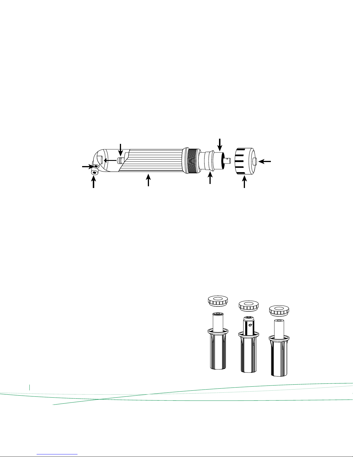
RO Membrane Installation:
First take the water purier out of its package. Open the water purier’s
outer cover. Unscrew the membrane shell cover inlet water connection
and take out the inlet water pipe. Then use the membrane shell wrench
to unscrew the membrane shell cover. Take the RO membrane out from
its package. Place the end of the membrane with the O-ring into
the reverse osmosis membrane shell (See Diagram 11) and push it in.
Finally, screw the membrane shell cover back on and use the membrane
shell wrench to tighten the membrane shell cover. Connect the inlet water
pipe into the inlet water connector on the membrane shell and screw in
the nut. Place the membrane shell card into the large single clip available
and attach the water purier cover back on.
Diagram 14
Diagram 15
Pure Water
O-ring
Membrane Shell
RO Membrane
Waste Water
Sealing Ring
Inlet Water
Membrane
Shell Cover
Membrane Installation Warnings:
The package of the reverse osmosis membrane contains a small amount
of protective solution in order to prevent microbiological contamination
of membrane components during storage and transportation.
• You should pay attention to the direction of the RO membrane during
installation.
• When installing the RO membrane; you should rst make sure that one
end of the membrane has an O-ring;
• During installation, be sure to put the end with the O-ring into the end
of the membrane shell with the pure water connection. If you install
the reverse osmosis membrane correctly, you will only need a little force
to mount it into the membrane shell. If you encounter too much
resistance, please do not force the reverse osmosis membrane into
the membrane shell. Doing so may cause permanent damage to the
membrane shell or membrane components (the membrane
manufacturer does not assume responsibility for returned components
due to damages incurred during installation).
• Damage to the membrane shell and reverse osmosis membrane
components inicted as a result of the abovementioned reasons is not
covered under the water purier’s warranty.
• Do not cut or try to disassemble the replaced membrane. RO membrane
can lter microorganisms and cutting or harming RO membrane may risk
on you and your environments health.
Installation of the Pre-Filters:
First take the pre-lters out of their packages. Tear off the packaging
of the lters in the order they should be installed: rst is the 5 micron PP
lter; second is the granular activated carbon lter, note that the rubber
pad must be installed on the top of the activated carbon lter; third is
the 10" block carbon (See Diagram 15).
ENG 15
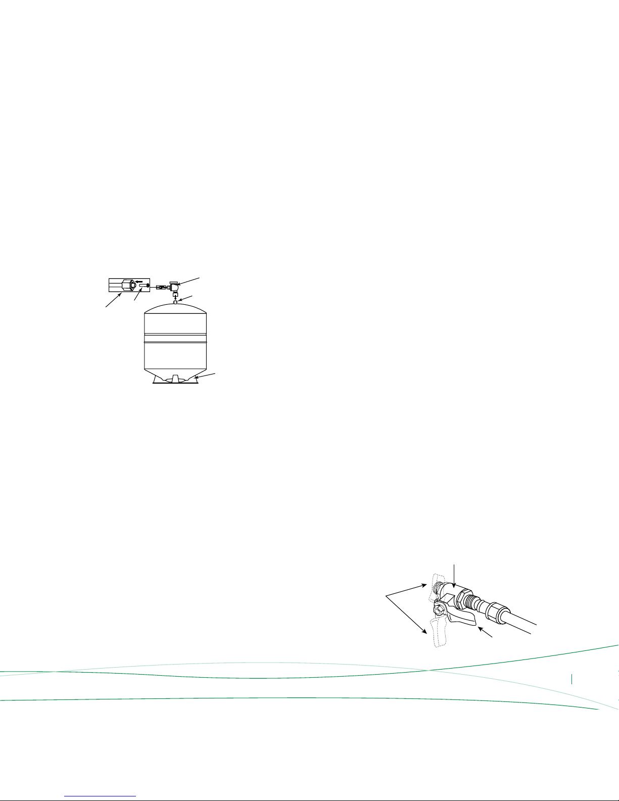
Installation of the Storage Tank:
First wrap teon tape around the water nozzle (4-5 turns). Use a little bit
of silica gel to prevent water leakage and loose connections. Then,
screw in the water tank ball valve into the water nozzle and nally
connect the water pipe to the storage tank: rst cut a suitable length of
the 6mm tubing, then put a screw nut on each end of the tubing. One
end of the piping should connect to the water purier labeled storage
tank connector, the other end should go in the storage tank ball valve
(See Diagram 16). Finally place the storage tank on the oor.
Installation Notes
When installing the water pipes, you should not install a drain stopper.
Furthermore, the screw nut on the water pipe bottom connector should
have no wire teeth exposed.
If the inlet water pipe is 9mm, you should ensure that the inlet water
pipe and connector have 30-40cm of straight piping to avoid pipe
bursting accidents caused by bending of the pipe.
If the power cord wiring needs to be longer, extend the cord according
to the wiring requirements and use an 8mm pinched tube to wrap
around the connection. Later, wrap insulating electrical tape
on the outside surface. Do not place the cord on the oor. The cord
should be suspended in the air or should follow a path above ground.
During installation, make sure that there is no electrical wiring or water
pipes embedded inside the walls where you will do the drilling.
Storage Tank
Diagram 16
6mm
Screw Nut
Storage Tank Ball Valve
Water Nozzle
Base
6mm
Pipe Stopper
Adjustment Methods
Make sure that the water route connections are correct, proper power supply is used and water supply is suitable.
Then, follow these steps to adjust the purier:
Open the tap water inlet valve and the water purier inlet water ball
valve and plug the purier in the power outlet (See Diagram 17).
Wait for the water purier to operate stably (for about 5-10 minutes).
Check each connection to make sure they are secure. Check to see if
there is any leakage from the membrane shell, lters, etc.
Close the pure water osmosis faucet and storage tank ball valve. Wait
approximately 30 seconds. Check to see whether or not the water
purier waste water and high pressure pump have stopped working.
Open the osmosis faucet. Check to see if the water is owing through
the faucet. If not, check to see whether the tap water pressure is too low,
whether or not the high pressure switch can be reset automatically.
Wait until the machine is operating properly, then close the inlet water
ball valve. After a short period of time, check to see if the machine stops
working, if it does not stop working, check to see whether
or not the low-pressure switch can be reset.
Perform a second check to make sure everything is ok. Now your water
purier is ready for use.
Diagram 17
Close
Inlet Water Valve
Open

ENG 16
Maintenance and Repair
The major components of this product are manufactured using plastic.
When using the water purier, always observe the integrity
of the equipment in order to ensure safe operation.
The post activated carbon lter may emit activated carbon powder
the rst time it is used. So do not open the water storage tank during
the rst hour when the water purier is put into operation. It is
recommended that the water produced during this period is disposed of.
Otherwise, the taste of the pure water may be unusual.
When you rst operate the water purier, the pure water TDS value may
be a little high. After operating for some time, the TDS value of the pure
water produced will gradually decrease until it is stable.
When you are using the water purier, the inlet water ball valve should
be opened and the pure water faucet needs to be turned on. When
you are not using water turn off the water faucet, the high pressure
switch will automatically cut off the water supply.
When you rst use the storage tank it is recommended that you discard
the rst tank of water; otherwise it may result in abnormal tasting pure
water.
It is recommended that you use the machine at least twice a week
to prevent microbiological contamination caused by the equipment lying
idle for an extended period of time, which in turn might cause odors
in the water.
If you did not use the machine for a longer period (more than one week),
before using puried water, follow the below steps:
- Turn off water inlet
- Cut off electricity
- Empty the water storage tank. Turn on the inlet water and electricity.
The machine will begin reverse osmosis.
If you did not use the machine for long periods (i.e 1-2 months), replace
the lters before using the machine.
In these “operation warnings”, “operation” refers to the power supply
being connected and/or the inlet water ball valve being open
so the water purier is in an operational state.
Operation Warnings
Filter Replacement Intervals
The lter replacement cycles for the various lters used in this purier is
derived from statistical indicators on the estimates of average tap water
usage. If there are considerable discrepancies between the supply
water quality, utilization rates and average indicators, there will be more
obvious differences between the lters actual replacement intervals
and estimated life-cycles and users may experience premature lter
clogging, premature failure, etc. If this occurs, lter replacement
intervals should be based on actual usage conditions. You should also
contact your local after-sales service department immediately to inform
the situation.
This machine’s estimated lter replacement cycle is based on average
household water consumption and is suitable only for residential use,
do not install this machine in places that require large volumes of water.
If the water volume requirements are large, our company offers
appropriate equipment tailored for commercial applications.
According to economic statistics on municipal tap water, a three person
family on average uses 10L of water a day. According to the water
volume and inlet water quality conditions, approximate ltering
volumes are as follows (the following data is for reference only):
WATER VOLUME (TONS)
7.5
7.5
10
50 - 75 - 80
6
USAGE PERIOD
3 Months
6 Months
6 Months
1-2 Years
1 Year
PROGRESSION
First: 10" 5m PP Filter
Second: 10" GAC Filter
Third: 10" Block Carbon Cartridge
Forth: Reverse Osmosis Membrane
Fifth: Post-Activated Carbon Filter

ENG 17
standard conditions. In actual usage, due to the fact that water quality
than the abovementioned estimates. This data is provided for reference
only. Under normal circumstances, if you witness the following indications,
membrane is blocked (determine that it was not caused
by a temperature drop);
Filter Replacement Method
should be disposed in a tightly closed garbage bag.
• Replacement of the 1st and 3rd stage lters:
First of all close the inlet water ball valve. Using the lter cartridge
wrench, unscrew the 1st and 3rd stage lter cartridges. Remove the old
lters and take the new lters out of their packaging. Finally place
the lters in the lter cartridges (Note: place the 5 micron PP lter
in the 1st stage lter cartridge, the block carbon in the 3rd stage
lter cartridge), using the lter wrench, tighten the lter cover.
• Replacing the 2nd stage lter:
First of all, close the inlet water ball valve. Using the lter cartridge
wrench, unscrew the 2nd stage lter. Remove the old lter and take
the new lter out of its packaging (note: the rubber pad on the lter
does not need to be taken off). Place the lter inside the lter cartridge
(note: the granular activated carbon lter should be placed with the
rubber pad end directed up towards the lter covers). Finally, use
the wrench to tighten the lter cover.
• For replacement of membrane elements please see
“RO Membrane Installation”
Warnings
• Notes before using replaced lters: After replacing the granular activated
carbon lter (2nd stage), you must rst ush out the machine in order
to avoid the activated carbon powder from the granular activated
carbon lter from owing into the 3rd stage lter or even
the RO membrane, which may result in damage to lter and membrane
components.
If there is dark colored water near the third stage lter, perform the
following steps:
- Turn off the water purier inlet water valve;
- Using the lter cartridge wrench, remove the water purier’s 3rd
stage lter;
- Place a large container near the 3rd lter cartridge cover to collect
the dark colored water;
- Open the inlet water valve, wait until the water is no longer dark;
- Close the inlet water valve, reinsert the 3rd stage lter into the lter
cartridge, and screw it in tight.
Please ush the post-activated carbon lter for 1-2 minutes before using.
• RO membrane water production volume:
The water output volume of the RO membrane component is
inuenced by inlet water pressure and water temperature.
Your equipment’s declared volume of 75GPD is tested under a net
pressure of 0.5MPa and inlet water temperature of 25°C .
If net pressure is less than 0.5MPa or if the inlet water temperature is
less than 25°C, water output volume of the RO membrane component
will be less than 75GPD.
• Storage tank capacity:
The storage tank on your equipment has a stated capacity of 3.6G.
However this gure is its theoretical capacity and its actual storage
capacity is about 70%-80% of the stated value, which is app. 2.5-2.8G.
• Disposal of old lters:
After replacing old lters, they cannot be cleaned and reused; it is
recommended that you dispose of them with solid waste garbage.

ENG 18
Notes
When any of the following situations occur, immediately disconnect
the water purier water source (close the inlet water ball valve) and/or
the power source and carry out repairs.
- If the water purier pipes or related components are leaking.
- If the water purier and/or components stop working.
- If any components leak electricity.
- If there are any other anomalies or failures.
When you go out or do not use the machine, disconnect the water
purier's water source (close the inlet water ball valve) and/or power
source.
If the water purier parts are damaged, it is recommended that the water
purier be entrusted to the manufacturer or distributor, service center,
or specialized technical personnel for replacement to prevent loss caused
by improperly performed maintenance, the manufacturer assumes
no liability for losses incurred as a result of operation or use that does
not conform with the instructions and reminders specied herein.
Packing List
LOTUS-72
1 Unit
1
1
1
1
1
1
1
1
1
1
1 Package
1
1
1
1 Roll
1
1
1
1
1
PARTS
Main Machine with Cabinet (Including Filters)
R.O. Membrane
Steel White Coating Bracket To Fit 3-Canister RO unit
Storage Tank
Filter Wrench
RO Booster Pump and Transformer 220V/50Hz with 2 Round Pin Plugs
High Pressure Switch
Low Pressure Switch
Check Valve and Male Elbow
Flow restrictor 300 ml 1/4”
Automatic shut off valve 1/4” (4 ways valve)
Standard Installation Kit consisting of
Water Inlet Valve ½”½” ¼” (3-way)
Chromed Ball Valve
Tank Shut Off Ball Valve 1/4”
Water Pipe
Drain Saddle Kit with 1/4" Screw
Chromed Osmosis Faucet
Faucet connector 1/4" x 7/16" FPT
Plastic Hanging Bracket to Fit Long Reach Faucet
User Guide (Including Warranty Card)
Table of contents
Languages:
Other WaterClinic Water Filtration System manuals


Popular Water Filtration System manuals by other brands

Atlantic Ultraviolet
Atlantic Ultraviolet Mighty Pure MP16A owner's manual

SunSun
SunSun CBG-500 Operation manual

Hayward
Hayward XStream Filtration Series owner's manual

Contech
Contech DownSpout StormFilter Operation and maintenance

Teka
Teka Airfilter MINI operating instructions

Wisy
Wisy LineAir 100 Installation and operating instructions

Schaffner
Schaffner Ecosine FN3446 Series User and installation manual

Pentair
Pentair FLECK 4600 SXT Installer manual

H2O International
H2O International H20-500 product manual

Renkforce
Renkforce 2306241 operating instructions

Neo-Pure
Neo-Pure TL3-A502 manual

STA-RITE
STA-RITE VERTICAL GRID DE FILTERS S7D75 owner's manual


