WaterCop SmartConnect User manual

System Description
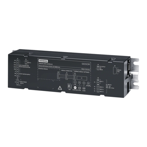
The WaterCop® SmartConnect is designedto work alongsidethe WaterCop® Pro Integrated System orWaterCop® Classic and
deliver real time notificationof leaks in your plumbing system. The SmartConnect unit is powered by the Pro panel or low
voltage Classic actuators through a straight through CAT5 or CAT6 cable. The SmartConnect can be connectedwithup to 50ft
of straightthrough CAT5 orCAT6cable canif neededto get stronger Wi-Fi reception. WCACT1, WPMS and WPMSH units will
need the external power supply (ACA100).
Check at the shipping package contains the following:
WaterCop SmartConnect device
Owner’sManual
Read Instructions before any installation is attempted. All sections of this Product Manual and accompanyingInstallation Guide
should be read and completely understood.
How the System Works
The SmartConnectunit receivesthe valve statusfrom the RJ45 outputs on boththe Pro and Monitoring Station panel and
Classic actuator. The information goesto a cloud serverand out to the SmartConnect App on your phone or tablet. The
SmartConnect App will notify when a valve changes state alerting you toa possible leak detection. Theapp can also notifyon a
loss of signal from the SmartConnectto the cloud servicewhich can indicate a loss of power or internet connection.
System Requirements
Smart Phone or tablet with the following:
Android Version 5.0 or higher/ iOS - 10.3 orhigher
Sim card or WI-FI connectivity
2.4 GHz Router with Protected Wi-Fi (with a password)
Bluetooth 4.1 or above
50’ CAT5E cable max to WaterCop
WCACT1,WPMSandWPMSH require additional power supply (ACA100) sold separately

System Set Up
PREFACE: Before setup on theWaterCop SmartConnect, verify if the device will be connected to the internet via wireless
or ethernet cable. If using wireless, verify signal strength before choosing the location ofthe SmartConnect device. When
running cable from the actuator or control panel to the SmartConnect, use CAT5 or CAT6, and keep the cable 50’ or (use
the supplied short cable if signal is adequate).
Setup
1) Remove WaterCop SmartConnect from packaging.
2) Mount WaterCop SmartConnect with the suppliedwall anchors or other methods to suit the location.
3) Once mounted, run a straight-through CAT5 or CAT6 cable (2’ CAT5 included)from theClassic actuator or Pro control
panel to the SmartConnect port marked ‘CONNECT TO VALVE ACTUATOR’. Power is supplied through the CAT5 or
CAT6 cable. If installed on a 120 VAC Classic actuator with antenna or the Monitoring station on an older WaterCop
Pro, the optional power supply, Part# ACA100 is requiredto power the SmartConnect.
Download the WaterCop SmartConnect App from the Google PlayStore on your Android device or from App Store on your
iOS device. Follow the steps below to create an account and setup the device/s.
Create Account
1) Open the SmartConnect App from your device.
2) Click on ‘Create account’.
3) Enter all information; the user name must be their valid email address.
4) PASSWORD: Use their first name initial CAPITAL, last name and Property number. Example password:
DAholt10 = Dena Aholt at 10 Harris Industrial Park
5) Click ‘Create’ at the top right of the screen.
1) Make sure Bluetooth and Location services areturned on prior toset up and have adequate cellular or Wi-Fi
connection.
2) Open the SmartConnect app and login with the the CUSTOMER’s credentials you just setup in the ‘Create Account’
section above.
3) To add and setup the SmartConnect, click the blue ‘Add’ button in the top right corner while physically near the
SmartConnect. After the default name‘WaterCop GW’ pops up, verify the MAC address is correct on the label on back
of device and carton and clickthe box toselect it.
4) Enter the Unit ID on the carton or SmartConnect, then click ‘OK’.
5) Click on the device to configure, once loaded click the settings icon at the top right.
6) Next to the MAC address, change the name of the device to the name of the client, building or address that makes
sense for identificationon the app.
7) If a Wi-Fi connection is desired, click the toggle button on the Wifi line then manually enter the Wi-Fi network and
password and click ‘Done’.
8) If no Wi-Fi is available or hard-wired connection is preferred, run a network cable from the router/modem to the port on
the SmartConnect marked “ETHERNET CONNECTION”. Make sure ‘Ethernet’ is selected on the app.
9) Press ‘GET’ on the location line under ‘Wifi’.
10) Enter the physical address of the SmartConnect. It will be displayed on the device screen.
11) Click ‘SAVE’. If it fails, try clicking ‘SAVE’again. It may take afew tries attimes.
12) Click the ‘<’ at the top left of the screen to go back to the device screen.
Setting Up Contacts & Testing Notifications
1) Click the ‘ > ‘ icon on the Contacts line under the address to view, enter and save contacts.
2) Click the ‘Add Contact’ at the bottom right and enter your contact info includingthe country code. Click ‘Done’.
3) Use the ‘ < ‘ icon to go back and check the contacts are showing; ex. 1 emails, 1 SMS.

4) Once saved andconnected, cycle the valve openand closedfrom the appto ensurethe SmartConnect is connected,
operating and sending notifications.
5) Delete your contact info by clicking the ‘ > ‘ icon on the Contacts line and then the ‘-‘ sign to the right. Click ‘yes’ when
asked “Are you sure?’.
6) Now add customer contact info and repeat this until all desired contacts are saved (only applicable if a list of contacts
were provided ).
7) Leave or emailthe instructions how toadd contactsso they can add them attheir conveniencenow and/or inthe
future.
FCC Information
ThisequipmenthasbeentestedandfoundtocomplywiththelimitsforaClassBdigitaldevice,pursuanttopart
15oftheFCCRules.Theselimitsaredesignedtoprovidereasonableprotectionagainstharmfulinterferenceina
residentialinstallation.Thisequipmentgenerates,uses,andcanradiateradiofrequencyenergyandifnotinstalled
andusedinaccordancewiththeinstructions,maycauseharmfulinterferencetoradiocommunications.However,
thereisnoguaranteethatinterferencewillnotoccurinaparticularinstallation.Ifthisequipmentdoescause
harmfulinterferencetoradioortelevisionreception,whichcanbedeterminedbyturningtheequipmentoffand
on,theuserisencouragedtotrytocorrecttheinterferencebyoneormoreofthefollowingmeasures:
•Reorientorrelocatethereceiver
•Increasetheseparationbetweentheequipmentandreceiver
•Connecttheequipmentintoanoutletonacircuitdifferentfromthattowhichthereceiverisconnected
•Consultthedealerforhelp.
Theuseriscautionedthatchangesandmodificationsmadetotheequipmentwithouttheapprovalofmanufacturer
couldvoidtheuser'sauthoritytooperatethisequipment.
Operationissubjecttothefollowingtwoconditions:
1. Thisdevicemaynotcauseinterference
2. Thisdevicemustacceptanyinterference,includinginterferencethatmaycauseundesiredoperationofthe
device
TosatisfyRFexposurerequirements,thisdeviceanditsantennasmustoperatewithaseparationdistanceof
atleast20cmfromallpersons
Limited Warranty
DynaQuip®ControlsCorporationwarrantstheelectricalcomponentsoftheWaterCop®SmartConnecttobefree
fromdefectsinmaterialandworkmanshipundernormaluseandifproperlyinstalledforaperiodofthreeyears
fromthedateofpurchase.Iffoundtobedefectiveasmentionedabove,itwillbereplacedorrepairedifreturned
prepaidalongwithproofofdateofpurchase.Thisshallconstitutethesoleremedyofthepurchaserandthesole
liabilityofDynaQuip®ControlsCorporation.Totheextentpermittedbylaw,theforgoingisexclusiveandinlieuof
allotherwarrantiesorrepresentationswhetherexpressedorimplied,includinganyimpliedwarrantyof
merchantabilityorfitness.InnoeventshallDynaQuip®ControlsCorporationbeliableforspecialorconsequential
damages.

Trouble Shooting
CannotseeorconnecttodeviceatAdd
screen
Turn the device’s Bluetooth offand back onto restartthe Bluetooth
radio and try again
RemovetheCAT5cableorpowersupplyfromthe
SmartConnectandreconnecttocyclepower
Noconnect,buttonsgrayafterconfiguring
Wi‐Finetwork
Verifynetworknameandpasswordarecorrect,appwill
notnotifyofincorrectnameorpassword
IftheissueremainscontactDynaQuipControls
ValveCONNECTIONLOSTmessage
Whileaddingandsettingupdevice,if30secondspass
beforeconnectingtoanetworkitwillsendthe
connectionlostmessage
Lossofinternetconnection,orlossofpowertothe
WaterCopsystem
Table of contents
