manuals.online logo
Brands
  1. Home
  2. •
  3. Brands
  4. •
  5. Proteco
  6. •
  7. Control System
  8. •
  9. Proteco Park Plus Series Operating and maintenance manual

Proteco Park Plus Series Operating and maintenance manual

Manuale d’Installazione e d’Uso
Installation and use instructions
Notice d'Installation et Utilisation
BARRIERA STRADALE
ROAD BARRIER
BARRIERE ROUTIERE
2010_10
Park Plus
Proteco S.r.l. Via Neive, 77 - 12050 Castagnito (CN) ITALY
Tel. +39 0173 210111 - Fax +39 0173 210199 www.proteco.net - [email protected]
F
GBI
1. AVVERTENZE GENERALI PER LA SICUREZZA
USO Avvertenze per l'utente
Le presenti avvertenze sono parte integrante ed essenziale del
prodotto e devono essere consegnate all'utilizzatore.
Leggerle attentamente in quanto forniscono importanti indicazioni
riguardanti la sicurezza di installazione, uso e manutenzione.
È necessario conservare queste istruzioni e trasmetterle ad
eventuali subentranti nell'uso dell'impianto.
Questo prodotto dovrà essere destinato solo all'uso per il quale è
stato espressamente concepito.
Ogni altro uso è da considerarsi improprio e quindi pericoloso.
Il costruttore non può essere considerato responsabile per
eventuali danni causati da usi impropri, erronei ed irragionevoli.
Evitare di operare in prossimità delle cerniere o organi meccanici
in movimento. Non entrare nel raggio di azione della porta o
cancello motorizzati mentre è in movimento.
Non opporsi al moto della porta o cancello motorizzati poiché può
causare situazioni di pericolo. Non permettere ai bambini di
giocare o sostare nel raggio di azione della porta o cancello
motorizzati. Tenere fuori dalla portata dei bambini i radiocomandi
e/o qualsiasi altro dispositivo di comando, per evitare che la porta
o cancello motorizzati possa essere azionata involontariamente.
In caso di guasto o di cattivo funzionamento del prodotto,
disinserire l'interruttore di alimentazione, astenendosi da qualsiasi
tentativo di riparazione o di intervento diretto e rivolgersi solo a
personale professionalmente competente. Il mancato rispetto di
quanto sopra può creare situazioni di pericolo.
L'utente può solo eseguire la manovra manuale.
Qualsiasi intervento di pulizia, manutenzione o riparazione, deve
essere effettuato da personale professionalmente competente.
Per garantire l'efficienza dell'impianto ed il suo corretto
funzionamento è indispensabile attenersi alle indicazioni del
costruttore facendo effettuare da personale professionalmente
competente la manutenzione periodica della porta o cancello
motorizzati.
In particolare si raccomanda la verifica periodica del corretto
funzionamento di tutti i dispositivi di sicurezza.
Gli interventi di installazione, manutenzione e riparazione devono
essere documentati e tenuti a disposizione dell'utilizzatore.
INSTALLAZIONE Istruzioni per l'installatore
L'installazione deve essere eseguita da personale
professionalmente competente. L'installazione, i collegamenti
elettrici e le regolazioni devono essere effettuati nell'osservanza
della Buona Tecnica e in ottemperanza alle norme vigenti.
Leggere attentamente le istruzioni prima di iniziare l'installazione
del prodotto. Una errata installazione può essere fonte di pericolo.
I materiali dell'imballaggio (plastica, polistirolo, ecc.) non vanno
dispersi nell'ambiente e non devono essere lasciati alla portata dei
bambini in quanto potenziali fonti di pericolo.
Prima di iniziare l'installazione verificare l'integrità del prodotto.
Non installare il prodotto in ambiente e atmosfera esplosivi:
presenza di gas o fumi infiammabili costituiscono un grave
pericolo per la sicurezza.
Prima di installare la motorizzazione, apportare tutte le modifiche
strutturali relative alla realizzazione dei franchi di sicurezza ed alla
protezione o segregazione di tutte le zone di schiacciamento,
cesoiamento, convogliamento e di pericolo in genere. Verificare
che la struttura esistente abbia i necessari requisiti di robustezza
e stabilità.
Il costruttore della motorizzazione non è responsabile
dell'inosservanza della Buona Tecnica nella costruzione degli
infissi da motorizzare, nonché delle deformazioni che dovessero
intervenire nell'utilizzo.
I dispositivi di sicurezza (fotocellule, coste sensibili, stop di
emergenza,ecc.) devono essere installati tenendo in
considerazione: le normative e le direttive in vigore, i criteri della
Buona Tecnica, l'ambiente di installazione, la logica di
funzionamento del sistema e le forze sviluppate dalla porta o
cancello motorizzati. I dispositivi di sicurezza devono proteggere
eventuali zone di schiacciamento, cesoiamento, convogliamento e
di pericolo in genere, della porta o cancello motorizzati.
Applicare le segnalazioni previste dalle norme vigenti per
individuare le zone pericolose. Ogni installazione deve riportare in
modo visibile l'indicazione dei dati identificativi della porta o
cancello motorizzati.
Prima di collegare l'alimentazione elettrica accertarsi che i dati di
targa siano rispondenti a quelli della rete di distribuzione elettrica.
Prevedere sulla rete di alimentazione un interruttore/sezionatore
onnipolare con distanza d'apertura dei contatti uguale o superiore
a 3 mm.
Verificare che a monte dell'impianto elettrico vi siano un
interruttore differenziale e una protezione di sovracorrente
adeguati.
Collegare la porta o cancello motorizzati a un'efficace impianto di
messa a terra eseguito come previsto dalle vigenti norme di
sicurezza.
Il costruttore della motorizzazione declina ogni responsabilità
qualora vengano installati componenti incompatibili ai fini della
sicurezza e del buon funzionamento. Per l'eventuale riparazione o
sostituzione dei prodotti dovranno essere utilizzati esclusivamente
ricambi originali.
L'installatore deve fornire tutte le informazioni relative al
funzionamento automatico, manuale e di emergenza
della porta o cancello motorizzati, è consegnare
all'utilizzatore dell'impianto le istruzioni d'uso.
1. GENERAL SAFETY PRECAUTIONS
USE Warnings for the User
The following precautions are an integral and essential part
of the products and must be supplied to the user.
Read them carefully as they contain important indications
for the safe installation, use and maintenance.
These instructions must be kept and forwarded to all
possible future user of the system.
This product must be used only for that which it has been
expressely designed. Any other use is to be considered
improper and therefore dangerous.
The manufacturer cannot be held responsible for possible
damage caused by improper, erroneous or unreasonable
use. Avoid operating in the proximity of the hinges or
moving mechanical parts.
Do not enter the field of action of the motorised door or gate
while in motion.
Do not obstruct the motion of the motorised door or gate as
this may cause a situation of danger.
Do not allow children to play or stay within the field of action
of the motorised door or gate. Keep remote control or any
other control devices out of the reach of children, in order to
avoid possible involuntary activation of the motorised door
or gate.
In case of breakdown or malfunctioning of the product,
disconnect from the mains, do not attempt to repair or
intervene directly and contact only qualified personnel.
Failure to comply with the above may create a situation of
danger.
The user can only execute the manual drive.
All cleaning, maintenance or repair work must be carried
out by qualified personnel.
In order to guarantee that the system works efficiently and
correctly it is indispensable to comply with the
manufacturer's indications thus having the periodic
maintenance of the motorised door or gate carried out by
qualified personnel.
In particular regular checks are recommended in order to
verify that the safety devices are operating correctly.
All installation, maintenance and repair work must be
documented and made available to the user.
INSTALLATION Instructions for the fitter
The installation must be carried out by qualified personnel.
The installation, the electrical connections and the settings
must be completed in conformity with good workmanship
and with the laws in force. Read the instructions carefully
before beginning to instal the product. Incorrect installation
may be source of danger.
Packaging materials (plastic, polystyrene, etc.) must not be
allowed to litter the environment and must be kept out of the
reach of children for whom they may be a source of danger.
Before beginning the installation check that the product is in
perfect condition. Do not install the product in explosive
areas and atmospheres: the presence of flammable gas or
fumes represents a serious threat to safety.
Before installing the motorisation device, make all the
structural modifications necessary in order to create safety
clearance and to guard or isolate all the compression,
shearing, trapping and general danger areas. Check that
the existing structure has the necessary strength and
stability.
The manufacturer of the motorisation device is not
responsible for the non-observance of workmanship in the
construction of the frames to be motorised, nor for
deformations that may occur during use.
The safety devices (photoelectric cells, mechanical
obstruction sensor, emergency stop, etc.) must be installed
taking into account: the provisions and the directives in
force, good workmanship criteria, the installation area, the
functional logic of the system and the forces developed by
the motorised door or gate.
The safety devices must protect against compression,
shearing, trapping and general danger areas of the
motorized door or gate.
Display the signs required by law to identify danger areas.
Each installation must bear a visible indication of the data
identifying the motorised door or gate.
Before connecting to the mains check that the rating is
correct for the destination power requirements. A multipolar
isolation switch minimum contact gaps of 3mm must be
included in the mains supply.
Check that upstream of the electrical installation there is an
adequate differential switch and a suitable circuit breaker.
Ensure that the motorised door or gate has an earth
terminal in accordance with the safety regulations in force.
The manufacturer of the motorising device declines all
responsibility in cases where components which are
incompatible with the safe and correct operation of the
product have been installed. For repairs or replacement of
products only original spare must be used.
The fitter must supply all information concerning the
automatic, the manual and the emergency operation of
the motorised door or gate, and must provide the user
of the device with the operating instructions.
1. CONSIGNES GENERALES DE SECURITE
Ces consignes sont parties intégrantes et essentielles
du produit et doivent être remises à l'utilisateur.
Lire ces consignes attentivement, car elles contiennent
des instructions concernant la sécurité, l'installation et
l'entretien de ce système.
Il est indispensable de conserver ces instructions et de
les transmettre à d'autres utilisateurs éventuels de ce
système.
Ce produit doit être destiné exclusivement à l'utilisation
pour laquelle il a été conçu. Toute autre utilisation est
inapproprié et par conséquent dangereuse.
Le constructeur ne peut être tenu pour responsable en
cas d'éventuels dommages causés par une utilisation
inappropriée. Ne pas entrer dans le rayon d'action de la
barrière lorsqu'elle est en mouvement. Ne pas
s'opposer au mouvement de la porte ou du portail
automatisé car cela pet être source de danger.
Ne laisser des enfants se tenir ou jouer dans le rayon
d'action de la barrière.
Garder hors de la portée des enfants les
radiocommandes et / ou tout autre dispositif de
commande, afin d'éviter que la barrière puisse être
actionnée involontairement.
En cas de panne ou de mauvais fonctionnement du
produit, débrancher le secteur et s'abstenir de toute
tentative de réparation ou d'intervention directe.
S'adresser uniquement à un professionnel compétent.
Le non-respect de ces instructions peut être
dangereux. En cas de panne l'utilisateur peut
seulement utiliser le dépannage manuel.
Afin de garantir l'efficacité du système et son
fonctionnement correct, il est indispensable d'observer
les instructions du constructeur en s'adressant à un
professionnel compétent pour l'entretien périodique de
cette barrière. Plus particulièrement il est recommandé
de procéder à une vérification périodique du
fonctionnement correct de tous les dispositifs de
sécurité. Les interventions d'installation, d'entretien et
de réparation doivent être documentées et mises à
disposition de l'utilisateur.
INSTALLATION Instructions pour l'installateur
L'installation doit être effectuée par un professionnel
compétent. L'installation, le raccordement électrique et
les réglages doivent être effectués selon règles de
Bonne et respecter la réglementation en vigueur.
Lire attentivement les instructions avant de procéder à
l'installation du produit. Une installation mal effectuée
peut être source de danger. Les matériaux de
l'emballage (plastique, polystyrène, etc..) ne doivent
pas être abandonnés dans la nature et ne doivent pas
être laissés à la portée des enfants, car ils sont une
source potentielle de danger.
Avant de procéder à l'installation, vérifier l'intégralité du
produit. Ne pas installer le produit à proximité des
matières explosives : La présence de gaz ou des
vapeurs inflammables représente un grave danger pour
la sécurité. Avant d'installer l'automatisme, apporter
toutes les modifications structurelles relatives à la
réalisation des distances de sécurité et la protection de
toutes les zones d'écrasement, de cisaillement,
d'entraînement et de danger en général.
Vérifier que la structure existante prévue pour installer
le produit ait les qualités requises de robustesse et de
stabilité. Le constructeur des automatismes n'est pas
responsable du non-respect des règles d'installation
professionnelles.
Les dispositifs de sécurité (photocellules, barres
palpeuses, arrêt d'urgence, etc.) doivent être installés
en tenant compte des normes et directives en vigueur,
des critères Techniques du site, des besoins de
fonctionnement du système et des forces dégagées par
la barrière. Les dispositifs de sécurité doivent protéger
les zones éventuelles d'écrasement, de cisaillement,
d'entraînement et de danger en général. Appliquer la
signalisation prévue par la réglementation en vigueur
pour localiser les zones dangereuses.
Avant de procéder au raccordement électrique,
s'assurer que les données de la plaquette signalétique
correspondent à celles du réseau d'alimentation
électrique. Prévoir sur le réseau d'alimentation un
dispositif de sécurité (disjoncteur, différentiel).
Relier la Barrière à un système de mise à la terre
efficace installé conformément aux normes de sécurité
en vigueur. Le constructeur des automatismes décline
toute responsabilité au cas où seraient installés des
composants incompatibles en termes de sécurité. En
cas de réparation ou de remplacement des produits,
des pièces de rechange originales doivent
impérativement être utilisées.
L'installateur doit fournir tous les renseignements
concernant le fonctionnement automatique, manuel
de secours de la barrière et remettre la notice
d'emploi à l'utilisateur.
2. MODELLI E CARATTERISTICHE – GENERAL OUTLINE – CARACTERISTIQUES DU PRODUIT
· Dati tecnici – Technical data – Caractéristiques tecniques
Park PLUS 3 Park PLUS 4 Park PLUS 6
Alimentazione – Power suppply - Alimentation 230 Vac ~ 50Hz
Corrente – Current - Courant 1,2 A1,5 A
Potenza assorbita – Absorbed power – Puissance absorb eé 200 W250 W
Coppia – Torque – Couple 280 Nm70 Nm
Condensatore– C – Condensateurapacitor 10 Mf16 Mf
Tempo di apertura – Opening time – Temps d’ouverture 10 sec.8 sec.3,5 sec.
Dimensione asta – Boom dimensions – Dimensions lisse 80x30x280x20x1,2
Lunghezza asta – Boom length – Longueur lisse 3 mt. Max ** 4 mt. Max * 6 mt. Max *
Temperature d’esercizio – Working temperature – Temp rature de serviceé - 20°C / +55°C
Peso operatore – Operator weight – Poid operateur 50 kg
Funzionamento intensivo – Intensive use – Fonctionnement intensif
* = 5,7 mt. passaggio utile–useful passage–passage utile P.U.
** = 2,7 mt. passaggio utile–useful passage–passage utile P.U.
· Dimensioni d’ingombro – Dimensions – Dimensions d’encombrement
GB FI
·Telaio portante in tubolare d'acciaio
elettrosaldato.
·Pannelli perimetrali in alluminio preverniciati
spessore12/10.
·Coperchio in acciaio verniciato e serratura
per accedere al comando manuale
d'emergenza.
·Asta in alluminio anodizzato di varie
lunghezzeconstriscerosserifrangenti.
·Molle di bilanciamento di quantità e tipologia
consone alla lunghezza dell'asta fornita a
corredobarraegiàregistratedallaProteco.
·Motore 230Vac monofase 50/60HZ
collegatoallacentraledicomando.
·Trasmissione con cinghia dentata e vite in
acciaio con boccola in materiale
autolubrificante.
·Interruttore di sicurezza per comando
manualeconmanovella.
·Finecorsa elettrico di apertura e chiusura
registrabile e collegato alla centrale di
comando.
·Finecorsa meccanico di apertura e chiusura
incorporatoeregistrabile
·Centrale elettronica di comando incorporata
eprecablata.
•
•
•
•
•
•
•
•
• O
•
•
Shell-frameinarc-weldedsteel
12/10paintedaluminiumpanels
Access to the emergency release
protectedbysteelcoverwithlock
Anodized aluminium boom with
reflectors
Pre-adjustedbalancingspring
accordingtotheboomlength
Pre-wiredsingle-phasemotor
230Vac~50/60Hz
Toothedtransmissionbeltandsteel
screwwithself-lubricatingnut
Safetymicro-switchthatinhibits
automaticmovementwhentherelease
coverisliftedup
peningandclosingelectriclimit-
Switch
Adjustablemechanicallimitsinopening
andclosing
Pre-wiredcontrolpanel
·Châssisenacierélectro-soudé.
·Panneaux 12/10 en aluminium
verni.
·Capot d'accès au déverrouillage
enacierverniavecserrure.
·Lisseenaluminiumanodise.
·Ressorts d'équilibrage préréglés
selonlalongueurdelalisse.
·Moteur 230Vac~50/60Hz branché
àlacartedegestion.
·Transmission par courroie dentée
et vis en acier avec bague
autolubrifiante.
·Interrupteur de sécurité pour
manœuvremanuelleàmanivelle.
·Fins de course électriques en
fermeture et ouverture reliées à la
cartedegestion.
·Fins de coure mécaniques en
o u v e r t u r e e t f e r m e t u r e
embarquéesetréglables.
· Cartedegestionbranchée.
Versione sinistra
Left side use
Utilisation à gauche
Versione destra
Right side use
Utilisation à droite
Asse rotazione barra
Boom’s rotation point
Axe rotation lisse
Passaggio utile P.U. Useful passage - passage utilisable
Realizzare una piazzola in calcestruzzo di
dimensioni minime di base 500x500 mm e 500 mm di
profondità su cui poter fissare l'armadio barra. La
superficie della piazzola deve essere perfettamente in
bolla. Al centro della piazzola bisogna prevedere uno o più
cavidotti per il passaggio dei cavi elettrici. Se la barra è
dotata della base a murare (pos.44) annegare la stessa
nella piazzola (fig. 4).
Prepare a suitable sized foundation plinth (at least
500x500mm wide and 500mm deep). Provide the facility
for one or more raceways for the routing of the electrical
cables. If the barrier is equipped with foundation plate
(44), embed it into the plinth. Make sure that the plinth
surface and the foundation plate are perfectly levelled
(fig.4)
Réalisez une base de fondation en béton que soit
au moins 500x500mm de côté et 50mm de profondeur.
Prévoyez une ou plusieurs gaines pour le passage des
câbles électriques. Si la barrière est équipée d'une platine
de fondation (44) posez-la dans le béton. Assurez-vous
que la surface du béton et la platine soient parfaitement au
niveau (fig.4).la place (fig. 4).
3. IMPIANTO TIPICO – STANDARD INSTALLATION – INSTALLATION STANDARD
N° FILI x SEZIONE
N° WIRES x SECTION
N° CABLES x SECTION
1) Interruttore di linea alimentazione Power supply switch Switch alimentation génerale
2) Barriera Barrier Barriere
4) Selettore a chiave Key switch Sélecteur a clé 2 x 1
6) Lampeggiante Blinker Clignotant 2 x 1,5
7) Fotocellula Photocells Photocellules RX 4 x 0,5
TX 2 x 0,5
11) Antenna Aerial Antenne RG S8
22) Pilastrino Post Potelet
23) Asta in alluminio Aluminium arm Lisse en aluminium
24) Appoggio fisso per asta Support Appui fixe
I GB F
4. INSTALLAZIONE E MESSA IN FUNZIONE – INSTALLATION – INSTALLATION MESSE EN FONCTION
4.1)
I
GB
F
4.2)
4.3)
I
GB
F
I
Appoggiare l'armadio sulla piazzola e fissarlo con 4 tasselli
metallici o chimici utilizzando i 4 fori presenti sul fondo dell'armadio barra
(se si dispone della base a murare bloccare l'armadio sulla base con i
dadi in dotazione). Attenzione per accedere al fondo dell'armadio barra
bisogna aprire il coperchio nero (pos.42) sbloccando la serratura
(pos.34) e sfilare verso l'alto il pannello frontale in alluminio.(fig.5)
Place the barrier on the plinth and fix it with 4 metal/chemical
plugs or fasten the barrier to the foundation plate using the supplied
nuts. Note: to get to the barrier's bottom unlock the black cover (42), lift it
up and slide the front metal panel up (fig.5).
Placez la barrière sur la base de fondation et fixez-la à l'aide de
chevilles métalliques ou chimiques par les 4 trous au fond ou vissez la
barrière à la platine de fondation avec les écrous en dotation. Attention :
pour accéder au fond de la barrière il faut déverrouiller la serrure, ouvrir
le capot noir (42) et faire glisser vers l'haut le panneau frontal (fig.5).
Azionare manualmente la vite (pos.60 vedi cap.10 esploso componenti)
con la maniglia (pos.43), finchè la ganascia porta asta (pos.66) è
orizzontale.
Bloccare l'asta sulla ganascia (pos.66) con il copri ganascia (pos.27) e le
4 viti M8 (fig.6).
Manovrare manualmente con la maniglia (pos.43) la salita e la discesa
dell'asta e verificare l'esatto intervento sia del finecorsa elettrico di
salita/discesa (pos.68 vedi fig.7) sia degli arresti meccanici (pos.31 vedi
fig.7) già preregistrati.
Collegare la linea di alimentazione, le linee dei comandi e degli
accessori alla centrale di comando (pos.134 vedi cap.10 esploso
componenti) secondo le normative vigenti. Collegare a massa.
Per i collegamenti elettrici alla centrale elettronica di comando e per
eventuali programmazioni e/o regolazioni utilizzare le istruzioni di
collegamento a corredo della stessa.
Il finecorsa (pos.69) blocca il funzionamento elettrico a coperchio aperta
(P.U. Passaggio utile - useful passage - passage utilisable + 270)
(P.U. Passaggio utile - useful passage - passage utilisable 352)
Foro passaggio cavi
Wiring hole
Trou de câblage
(P.U. Passaggio utile - useful passage - passage utilisable + 180)
Pannello frontale
Front panel
Panneau frontal
4.4)
F
F
I
Release the barrier manually with the handle (43) until the
boom-clamp (66) comes to the horizontal position. Fasten the
boom on the clamp with the supplied cover (27) and the M8
screws (fig.6). Manually operate the barrier up and down by the
release handle and check that the pre-adjusted mechanical stops
(31) grant the perfect horizontal and vertical alignment (fig. 7).
Make sure that the electric limit-switch (68) is correctly activated
both in opening and closing. Wire the main power, controls and
accessories to the control panel (134). Make sure that all the
electrical wirings comply with current UE regulations and national
standards required. Provide the installation with a safety ground
connection. For the electrical wirings, please refer to the dedicate
instructions of the control panel.
A safety micro-switch (pos. 69) stops the barrier from moving if
the cover is lifted up.
Déverrouillez manuellement la barrière avec la manivelle
(43) jusqu'à ce que l'étau de la lisse (66) soit en position
horizontal. Fixez la lisse à l'étau à l'aide de sa patte de couverture
(27) et des vis M8 (fig.6). Manœuvrez manuellement la barrière
dans les deux directions et vérifiez le fonctionnement correct soit
des fins de course électriques (68) soit des fins de course
mécaniques (31) pour un alignement parfait de lisse en ouverture
ainsi que en fermeture (fig. 7).
Branchez l'alimentation principale, les accessoires de commande
et de sécurité à la carte de gestion (134). Assurez-vous que tous
les branchements électriques correspondent aux directives UE et
aux normes nationales.
Reliez l'automatisme à un système de mise à la terre. Pour tout
ce qui concerne les branchements électriques à la carte de
gestion la programmation et les réglages, veuillez consulter la
notice de la carte de gestion.
Un micro-interrupteur de sécurité (pos. 69) empêche le
mouvement automatique si le capot est levé.
L'eventuale regolazione del finecorsa elettrico (pos.68) di
salita/discesa si effettua agendo sulle 2 camme (pos.24) poste
sull'albero di manovra che vanno ad intercettare il finecorsa nei
2 sensi di marcia. Il finecorsa elettrico di salita /discesa deve
attivarsi un attimo prima che l'arresto meccanico (pos.31)
intervenga (fig. 7).
In case any adjustment of the electrical limit-switches is
needed, move the two cams (24) on the shaft accordingly. Set
the electrical limit-switches (fig. 7) so that the boom stops just
before reaching the mechanical stops (31).
Pour régler éventuellement les fins de course électriques
(68) agissez sur le deux cames (24) positionnées sur l'arbre de
manœuvre. Réglez les fins de course soit en ouverture soit en
fermeture de manière que la lisse s'arrête juste avant le fin de
course mécanique (31) (fig.7).
I USARE SOLO E TASSATIVAMENTE ASTE IN ALLUMINIO
DI dim. 80x30x2 mm PER PARK PLUS 4/6,
dim. 80x20x1,2 mm PER PARK PLUS 3, NON AUMENTARE MAI
LA LUNGHEZZA MASSIMA DELL’ASTA.
SE SI UTILIZZANO ALTRE DIMENSIONI E PESO DELL’ASTA
DECADE LA GARANZIA
TO BE USED ONLY WITH ALUMINIUM BOOMS
STRICTLY MEETING THE FOLLOWING SPECIFICATIONS:
BOOM dimensions 80X30X2 mm FOR PARK PLUS 4 & 6 AND
80X20X1,2 mm FOR PARK PLUS 3.
DO NEVER INCREASE THE RECOMMENDED BOOM LENGTH.
THE WARRANTY TERMS AUTOMATICALLY LAPSE IN CASE
OF USE WITH NON COMPLYING BOOMS
UTILISER EXCLUSIVEMENT AVEC LISSES CONFORMES
À LES SPÉCIFICATIONS SUIVANTES: LISSES DE dimensions
80X30X2 mm POUR PARK PLUS 4 ET 6 ET 80X20X1,2 mm
POUR PARK PLUS 3.
NE JAMAIS DÉPASSER LA LONGUEUR MAXIMALE DE LA LISSE.
TOUS LES DROITS DE GARANTIE TOMBENT
AUTOMATIQUEMENT EN CAS D'EMPLOI AVEC LISSES NON
CONFORMES À LES DONNÉES INDIQUÉES.
GB
GB
F
GB
Per barra destra/sinistra vedi fig.1
L'eventuale trasformazione deve essere effettuato da personale qualificato:
Ruotare la PIASTRA SUPPORTO CENTRALE di 180” in modo da poter intervenire sul lato
opposto a quello attuale.
Smontare la ganascia porta asta (pos.66 fig.6 ) fissata all'albero di manovra e riposizionarla
sul lato opposto dell'albero di manovra previo smontaggio del tappo in plastica di colore nero
che andrà a chiudere il foro lasciato libero sul lato opposto. Attenzione il serraggio della vite a
brugola che fissa la ganascia all'albero di manovra deve rispettare i valori riportati sulla targa
adesiva presente sulla ganascia (vedi fig. 8).
This operation must be carried on by qualified personnel only. Please refer to Fig.1.
Open the black cover and slide the front panel up. Reverse the plate with the control panel at
180° so that you can program the control panel from the opposite side. Slide the front panel
down again and remove the black cap on it. Take the boom-clamp away from the back panel
and fix it on the opposite side. Close the hole on the back panel with the black cap. When
tightening the boom-clamp's screw on the main shaft pay attention to comply with the values
written on the clamp's sticker (fig.8).
L'éventuelle transformation d'emploi (ouverture à droite ou à gauche) de la barrière
doit être effectuée par un professionnel compétent. Pour toute référence voir fig.1.
Ouvrez le capot noir et faites glisser le panneau frontal vers l'haut. Tournez à 180° la patte
support de la carte de gestion au fin d'accéder à la programmation de la carte par l'autre
côté. Baissez de nouveau le panneau et enlevez son bouchon noir. Décrochez l'étau de la
lisse (66) du panneau derrière et fixez-le sur le panneau frontal. Couvrez le trou sur le
panneau derrière avec le bouchon noir. En serrant la vis de fixation de l'étau à l'arbre de la
barrière respectez les données indiquées sur le sticker (fig.8)
· Bilanciamento – Boom balancing – Équilibrage
PREMESSA:
Le barre vengono fornite al cliente già bilanciate e registrate in funzione della lunghezza dell’asta.
In caso di installazione con grembiulina fare riferimento alle apposite istruzioni.
Attenzione: non bisogna assolutamente applicare oggetti aggiuntivi, modificare la lunghezza e la
tipologia dell’asta modificando le regolazioni delle molle di bilanciamento rispetto alla
fornitura originale PROTECO. Ciò può essere pericoloso e comprometterne il
funzionamento e la durata.
NOTE :
The barrier's springs are already pre-balanced according to the boom length and the use of a mobile support.
In case of use with hanging rack (PARK Plus 4 only), please refer to dedicate hanging rack's instruciotns.
Warning :
NOTE :
Les ressorts de la barrière sont déjà préréglés en fonction de la longueur de la lisse et de l'emploi d'un appui mobile.
En cas d'emploi avec rideau de lisse (pour PARK Plus 4 seulement), consultez la notice fournie avec le rideau de lisse.
Attention :
· Trasformazione da destra a sinistra – Changing from right side to left side– Trasformation de droite à gauche
I
I
GB
GB
F
F
5)
we recommend you not to change the spring balancing, not to add further accessories to
the boom and not to modify the boom's length and dimensions. Any alteration of the pre-
adjusted balancing may cause serious danger to persons and objects and may prejudice
the correct working and the durability of the automation.
ne pas changer le réglage des ressorts ou rajouter au système des accessoires
supplémentaires ou modifier la longueur de la lisse. Toute altération des réglages
originaux Proteco peut causer du danger et menacer le fonctionnement et la durée de
l'automatisme.
6)
7. COMANDO MANUALE D’EMERGENZA – EMERGENCY MANUAL DRIVE – OUVERTURE MANUELLE
I
F
In caso di black-out o panne, per azionare manualmente la
barriera, bisogna:
·Aprire il coperchio (pos.42) aprendo la serratura (pos.34).
·Inserire la maniglia (pos.43) nell'innesto comando manuale (pos.32)
con sede esagonale presente sulla vite che movimenta l'albero
oscillante.
·Ruotare la maniglia in senso orario o antiorario per movimentare
l'asta nei 2 sensi.
Ultimata la manovra manuale la maniglia va ricollocata nella sua
sede (vedi fig.10) ed il coperchio va nuovamente chiuso a chiave.
Attenzione con il coperchio aperto non è possibile, per ovvii motivi di
sicurezza, il comando motorizzato della barriera poiché il finecorsa di
sicurezza (pos.69) è attivato.
To manually drive the barrier, in case of power-cut or break-
down, please follow this procedure:
Unlock and open the black cover
Insert the handle(42) into the hexagonal seat on the main shaft
Turn the handle clockwise and anticlockwise to open and close the
barrier
Once the operation is completed, put the handle back again (fog. 10),
then close and lock the black cover.
Warning: for safety reasons, a micro-switch (69) prevent the barrier
from moving automatically as long as the black cover is open.
Pour actionner manuellement la barrière, en cas de coupure de
courant ou de panne, suivez cette procédure :
Déverrouillez et ouvrez le capot noir
Introduisez la manivelle(42) dans son clabot hexagonal sur l'arbre de
transmission(32)
Tournez la manivelle dans le sens des aguilles d'une montre et dans
le sens contraire pour ouvrir et fermer la barrière.
Quand vous avez terminé la manœuvre, rangez la manivelle dans sa
place (fig. 10) et fermez la capot noir.
Attention: pour raisons de sécurité, un micro-interrupteur (69)
empêche le mouvement automatisé de la barrière lorsque le capot
noir est ouvert.
GB
8. INCONVENIENTI CAUSE E RIMEDI – TROUBLESHOOTING - SOLUTION DES PROBLEMES
INCONVENIENTE CAUSA PROBABILE RIMEDIO
Alimentazione di rete 230 volt assente Controllare l’interruttore principale
La fotocellula è ostruita o non funzionante Rimuovere l’eventuale ostacolo o
verificare il funzionamento e i
collegamenti
Il coperchio (pos.42) è aperto Chiudere il coperchio
Ad un comando con il radiocomando o
con il selettore a chiave, la barriera
non apre
Presenza di STOP di emergenza Controllare eventuali comandi di STOP
L’automazione funziona con il selettore
a chiave o con la pulsantiera, ma non
con il radiocomando
Il radiocomando non è stato memorizzato
oppure è guasto oppure la batteria è scarica
Eseguire la procedura di riconoscimento
del radiocomando sul ricevitore radio o
sostituire la batteria con una nuova
N.B.: Se l’inconveniente permane, contattare il proprio Rivenditore o l’ufficio tecnico PROTECO.
FAILURE PROBABLE REASON POSSIBLE SOLUTION
230VAC power supply lack Check the main switch
The photocell beam is interrupded by an
obstacle or the photocell doesn't work Remove the obstacle and check the
connections of the accessories
The cover 42 is open Close the cover
The barrier doesn’t open on a
command given with the remote
Emergency STOP activated Check possible switches or commands
The barrier doesn’t open on a The remote control has not been
memorized, or it is damaged, or the
battery is low
Memorize the remote control in the
control panel or replace the battery
N.B.: If the failure remains, please contact your Retailer or the nearest Customer Service.
PROBLEMES CAUSE PROBABLE REMEDE
Absence d'alimentation 230V Vérifiez l'interrupteur principal de l'alimentation
Le capot noir (42) est ouvert Fermer le capot
Présence d'une commande
N.B.: Si le problème persiste, contactez votre revendeur ou le service client de PROTECO
I
GB
F
control or the key switch.
command given with the remote
control, but the key switch works properly
Après une commande donnée par
le contacteur à clé ou par la
radiocommande la barrière ne
bouge pas
L'automatisme marche avec le
contacteur à clé mais pas avec la
radiocommande
Un obstacle empêche le rayon des
photocellules
de STOP d'urgence
La radiocommande n'est pas mémorisée
sur le récepteur ou est en panne ou la
batterie est faible
Enlevez l'obstacle ou vérifiez les
branchements et le
fonctionnement des photocellules
Vérifiez les éventuelles
commandes de STOP
Faites l'apprentissage de la
radiocommande sur le récepteur
ou remplacez la batterie
9. PIANO DI MANUTENZIONE – MAINTENANCE PROGRAM – PLAN D’ENTRETIEN
I GB F
Per garantire l'efficienza del prodotto è
indispensabile che personale
professionalmente competente effettui
la manutenzione nei tempi prestabiliti
dall'installatore, dal produttore e dalla
legislazione vigente.
Gli interventi di installazione,
manutenzione, riparazione e pulizia
devono essere documentati. Tale
documentazione deve essere
conservata dall'utilizzatore, a
disposizione del personale competente
preposto.
Per un corretto funzionamento nel
tempo occorre applicare il seguente
piano di sorveglianza e manutenzione :
1. Controllo periodico semestrale del
corretto funzionamento delle
fotocellule con funzione di arresto
ed inversione del moto in fase di
chiusura.
2. Controllo periodico semestrale del
corretto funzionamento del
lampeggiante.
3. Controllo periodico semestrale del
corretto funzionamento della
eventuale costa applicata sul lato
inferiore dell'asta.
4. Controllo periodico semestrale di
eventuali altri dispositivi di
protezione installati.
5. Controllo periodico semestrale del
corretto funzionamento dei finecorsa
elettromeccanici.
6. Controllo periodico semestrale dei
dispositivi di comando (pulsantiere,
impianti radio, ecc.)
7. Controllo periodico semestrale della
corretta tensione della cinghia
dentata del motore.
8. Lubrificazione periodica trimestrale
degli organi in movimento.
9. Controllo periodico semestrale del
corretto funzionamento del sistema
per comando manuale di
emergenza.
10. Controllo periodico annuale del
corretto serraggio della bulloneria.
Controllo annuale delle molle di
bilanciamento.
La periodicità del piano di
manutenzione, in caso di utilizzo
intensivo, va dimezzato.
A professional maintenance, carried out
by qualified personnel, is periodically
needed according to the installer's
recommendations and to the national
safety standards.
Any maintenance, repairing or cleaning
operation has to reported in writing and
kept by the end-user for future
reference of the professional staff.
Steps for periodical maintenance and
checking:
1. Check the photocells (stop function
and reverse function when closing)
twice a year
2. Check the blinker twice a year
3. Check the sensitive edge on the bar
(if present) twice a year
4. Check twice a year any further
safety device connected to the
automation
5. Check the correct working of the
electrical limit-switches twice a year
6. Check the main controls (push-
button, remote controls,…) twice a
year
7. Check the toothed-belt's tension
twice a year
8. Grease quarterly the main gears
9. Check the emergency manual drive
twice a year
10. Check the bolts' tightening and the
springs balancing once a year
In case of intensive use of the
automation, repeat this procedure twice
frequently.
Pour un fonctionnement sûr et efficace
de l'automatisme, il est indispensable
que un professionnel compétent effectue
un entretien périodique selon les
indications de l'installateur, du
constructeur et conformément à les
normes de sécurité en vigueur.
Les interventions d'installation,
d'entretien et de réparation doivent être
documentées et mises à disposition de
l'utilisateur pour toute référence future.
Plan de surveillance et entretien:
1. Contrôle du fonctionnement des
photocellules (fonction de stop et
inversion de la direction en
fermeture) tous les six mois
2. Contrôle du fonctionnement du
clignotant tous les six mois
3. Contrôle du fonctionnement de la
barre palpeuse (si installée) tous les
six mois
4. Contrôle du fonctionnement des
autres dispositifs de sécurité
éventuellement installés tous les six
mois
5. Contrôle du fonctionnement des fins
de course électriques tous les six
mois
6. Contrôle des dispositifs de
commande (commandes radio,
boutons, etc.) tous les six mois
7. Contrôle de la tension de la courroie
dentée tous les six mois
8. Graissage des engrenages selon
fréquence d'utilisation (2 fois par an
obligatoire)
9. Contrôle du fonctionnement correct
du déverrouillage manuel de la
barrière
10. Contrôle annuel du serrage de la
boulonnerie et d'équilibrage des
ressorts
En cas d'usage intensif de
l'automatisme, répétez ce programme
d'entretien et de contrôle avec une
fréquence plus rapprochée.
10. ESPLOSO COMPONENTI – SPARE PARTS LIST – VUE ECLATÉE
Pos. Disegno N° Codice Qtà Descrizione Description Déscription
1 B1000A01 NN134F 1 Telaio Frame Cadre
15 B1000A15 NN132F 1 Supporto motore Motor plate Plaque moteur
16 B1000A16 NN133G 2 Supporto boccola Bush holder Support douille
18 B1000A18 T341F 1 Boccola porta cuscinetti Bush for bearings Douille pour roulement
19 B1000A19 T342F 1 Perno aggancio molle Pin for spring Guojon pour ressort
23 B1000A23 NN135F1 1 Forcella sostegno chiocciola Nut support Fourche de support pour noix
24 B1000A24 NN136F1 2 Camma completa per finecorsa Cam for limit switch Camme pour fin de course
26 B1000A26 T346F 2 Boccola antivibrante (rossa) Antivibration bush (red) Douille antivibration (rouge)
27 B5000A27 LL147F 1 Copri ganascia Cover for boom clamp Couvre-etau
30 B1000A30 LL143F 1 Fermo per registro arresto meccanico Mechanical stop Butee mécanique
31 B1000A31 T348F 2 Vite per finecorsa meccanico Screw for mechanical stop Vis pour butee mécanique
32 B1000A32 T349F 1 Innesto maniglia comando manuale Bush for handle Boucle pour manivelle
34 B5000A34 AF069F 1 Blocchetto a chiave con leva Key block with lever Serrure et clef avec levier
36 (*)(**) B1000A36 PPR72F 1 Puleggia dentata Toothed pulley Poulie crantée
Z72 Xl03 7Z72 Xl037 Z72 XL037
37 B1000A37 PPR15F 1 Puleggia dentata Toothed pulley Poulie crantée
Z15 Xl037 Z15 Xl037 Z15 Xl037
38 B1000A38 LL152A 1 Pannello laterale A Back panel A Panneaux laterales A
39 B1000A39 LL152B 1 Pannello laterale B Lateral panel B Panneaux laterales B
40 B1000A40 LL152C 1 Pannello laterale C Lateral panel C Panneaux laterales C
41 B1000A41 LL152D 1 Pannello laterale D Front panels D Panneaux laterales D
42 B1000A42 LL152E 1 Coperchio Cover Capot
43 B1000B43 BM8 1 Maniglia comando manuale Handle for manual drive Manivelle depannage manuel
44 B1000A44 NN146F1 1 Base a murare con viti saldate Foundation plate Plaque de scellement
46 B1000A46 MS033Z 1 Molla ritegno coperchio laterale Panel spring Ressort
52 B1000A52 CB018 2 Boccola sinterizzata Bush Douille
53 B1000A53 T446F 2 Grano M14x35 Dowel M14 X 35 Grain
60 (**) B1013A01 T514F 1 Vite Ø20 TPN Screw Ø 20 Vis sans fin
61 (**) B1013A02 T515F 1 Chiocciola Ø20 TPN Nut Nois
62 (*)(**) PCD180XL037 1 Cinghia dentata Toothed belt Courroie crantée
65 B5000A52 LL183F 1 Supporto per quadro di comando Control panel plate Support pour centrale
66 B5000A53 NN225F 1 Ganascia con fresatura Boom clamp Etau
67 B1004A00 EM HP0,3 220V 1 Motore monofase flangiato Motor Moteur
68 B1002A00 EF93CAS 1 Finecorsa barra Limit switch barrier Fin de course barriére
69 B1003A00 EF93CAS 1 Finecorsa coperchio Limit switch cover Fin de course capot (stop)
70 Molla di bilanciamento Balancing spring Ressort
71 AF062F 1 Tappo nero Ø80x1,5 Black cap Bouchon noir
72 (*)(**) AF015F 4 Tappo 40x30 Plug Bouchon
73 (*)(**) 1 Asta alluminio anodizzato 80x30x2 Galvanized aluminium arm Lisse alumin
74 SC6/20 1 Linguetta 6x6x20 Forma A UNI 6604 Tab Patte
75 AF018F Strisce rosse rinfrangenti Red reflective bands Bandes réfléchissantes rouges
76 B1000A56 AF079F 2 Etichetta Sticker Sticker
100 BTCANM10 2 Tenditore M10 Tensioner Tendeur
101 MST23/8,2/0,9 8+8 Molla a tazza Ø23x8,2x0,9 Bauer sprig Ressort Bauer
102 CNC30203A 2 Cuscinetto rulli conici Ø17xØ40x13,25 Ball bearing Roulements coniques
103 BV10MA25Z 1 VTE M10x25 Screw Vis
104 BD10MAAB 4 Dado basso autobloccante M10 Nut Ecrou
105 BB10MA70B 4 VTCEI M10x70 Screw Vis
106 BR10/20Z 9 Rondella Ø10xØ20 Spessore 2 Washer plain Rondelle
107 BD14MAZ 4 Dado M14 Nut Ecrou
108 SSE14 2 Seeger esterno Ø14 External circlips Anneau élastique
109 SSE40 2 Seeger esterno Ø40 External circlips Anneau élastique
110 BLBM14x35B 2 Grano punta_cilindrica M14x35 Dowel Grain
111 BL6MA6B 1 Grano M6x6 Dowel Grain
112 BR12/36Z 1 Rondella Ø12xØ36x2,5 Washer plain Rondelle
113 BD12MAZ 2 Dado M12 Nut Ecrou
114 AR/INGV 1 Ingrassatore Injector for grease Graisseur
115 BV8MA65Z 2 VTE M8x65 Screw Vis
116 BD8MAAB 2 Dado basso autobloccante M8 Nut Ecrou
117 BB6MA10Z 1 VTCEI M6x10 Screw Vis
118 BD8MAB 4 Dado basso M8 Nut Ecrou
119 BR5/11Z 4 Rondella Ø5xØ10x1 Washer plain Rondelle
120 BB5MA18Z 4 VTCEI M5x18 Screw Vis
121 BL6MA10B 2 Grano M6x10 UNI 5923 Dowel Grain
122 B1000A58 BR10,5/25T 2 Rondella per boccola antivibrante Washer plain Rondelle
123 BD10MAZ 5 Dado M10 Nut Ecrou
124 BVA5,5/16Z 8 VTE M5,5x16 flangiata autoforante Screw Vis
125 BC4MA25Z 4 VTC M4x25 Impronta a croce Screw Vis
126 BR4/9Z 8 Rondella Ø4xØ9x1 Washer plain Rondelle
127 BD4MAZ 4 Dado M4 Nut Ecrou
128 BM5/8ALL 2 Ribattino Ø5x8 Rivet Rivet
129 SC4/10 1 Linguetta 4x4x10 Forma A UNI 6604 Tab Patte
130 BB16MA70B 1 VTCEI M16x70 Screw Vis
131 BR8/17Z 4 Rondella Ø8xØ16x1,5 Washer plain Rondelle
132 (*)(**) BV8MA45Z 4 VTE M8x45 Screw Vis
133 BB5MA15B 4 VTCEI M5x15 Screw Vis
Pos. Disegno N° Codice Qtà Descrizione Description Descripcion
36 B1000A34 PPR44F 1 Puleggia dentata
Z44 Xl037 Z44 Xl037 Z44 XL037
62 PCD150XL037 1 Cinghia dentata Toothed belt Courroie crantée
72 AF014F 2 Tappo 80x20 Plug Bouchon
73 1 Asta alluminio anodizzato 80x20x1,2 Galvanized aluminium arm Lisse alumin
132 BV8MA35Z 4 VTE M8x35 Screw Vis
Toothed pulley Poulie crantée
(*) Variante per barriera tipo Park PLUS 3
· Molle di bilanciamento (pos. 70) – Balancing springs – Ressort d’équilibrage
Codice
Code
Code Df De
Lunghezza molla
Spring length
Longueur ressort
MPKR35 2,5 24,5 540
MPKR09 3,5 30 290
MPKR36
(MTK60)
(MTK60)
(MTK60)
(MTK60)
(MTK60)
4,8 40 435
·
Molle da adottare in base alla lunghezza asta – Spring in relation to the boom’s length
Ressort à utiliser selon la longeur de la lisse
Park PLUS 3 Asta - Boom – Lisse 80x20x1,2
Lung. Asta - Length
Long. lisse Tipo molla - spring
Ressort
3m N°1 MPKR35
Park PLUS 6 Asta - boom - lisse 80x30x2
Senza piedino mobile
Withouth mobil support
Sans appuy mobil
Con piedino mobile
With mobile support
Avec appuy mobil
Con gremb. senza piedino mobile
With skirt withouth mobil support
Avec ratelier sans appuy mobil
Con gremb. Con piedino mobile
With skirt with mobil support
Avec ratelier avec appuy mobil
Lung. asta
Lenght arm
Long. lisse
Tipo molla
Type spring
Type ressort
Misura X
Measure X
Mesure X
Tipo molla
Type spring
Type ressort
Misura X
Measure X
Mesure X
Tipo molla
Type spring
Type ressort
Misura X
Measure X
Mesure X
Tipo molla
Type spring
Type ressort
Misura X
Measure X
Mesure X
4 m N°2 MPKR09 250 mm N°2 MPKR09 215 mm N°2 MPKR36 220 mm
n°1 MPKR36
n°1 MPKR09
190 mm
200 mm
6 m N°2 MPKR36 220 mm N°2 MPKR36 195 mm
Park PLUS 4 and 80x2
80x2
Colore
Colour
Coulours
Marrone-Brown- Marrone
Silver
Nonverniciata
Notpainted- Pas peint
(MTK5F)
(MTK25Z) (MTK25Z)
(MTK25Z)
(MTK25Z)
(MTK5F)
11. ACCESSORI OPZIONALI – OPTIONALS – ACCESSOIRES SUR DEMANDE
Articolo
Item
Articolo
Codice
Code
Code
Applicazione
Application
Application
Piedino appoggio asta fissaggio sottoasta
Support mobile fixage sous la lisse
Park PLUS 4
Piedino appoggio asta fissaggio al suolo
Support arm on the ground
Support lyre à fixer au sol
Rastrelliera alluminio L1 max 4m
Hanging rack max L1 max 4m
Rideau de lisse aluminium L1 max 4m
Lampeggiante
Blinker
Clignotant
Base a murare
Foundation plate
Platine de fondation
NN146F1
Park PLUS 3
Park PLUS 4
Park PLUS 6
Park PLUS 3
Park PLUS 4
Park PLUS 6
Park PLUS 3
Park PLUS 4
Park PLUS 6
Park PLUS 3
Park PLUS 4
Park PLUS 6
PRODOTTI
PRODUITS
PRODUCTS
ERZEUGNIS
PRODUCTOS Proteco S.r.l. Via Neive, 77 - 12050 Castagnito (CN) ITALY
Tel. +39 0173 210111 - Fax +39 0173 210199 www.proteco.net - [email protected]

This manual suits for next models

3

Other Proteco Control System manuals

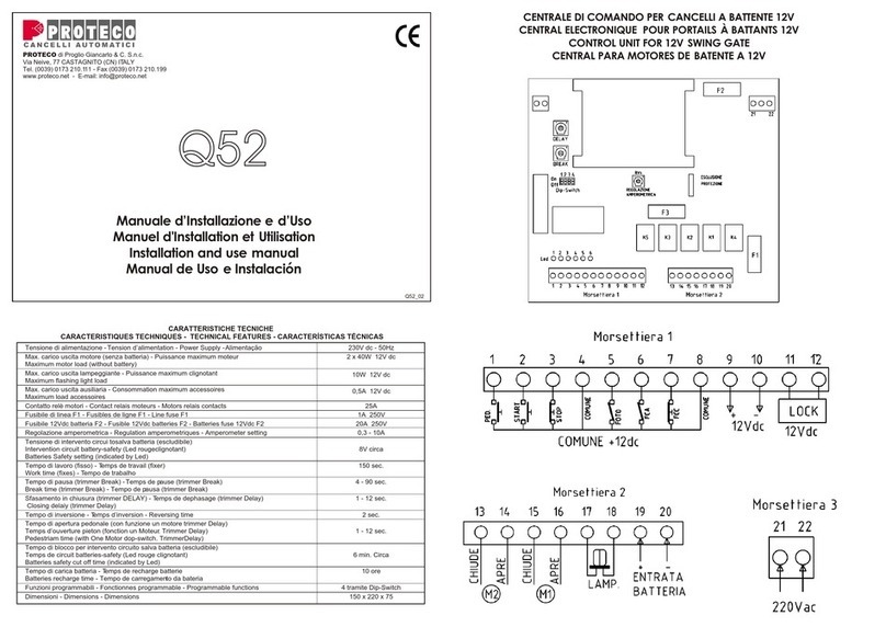
Proteco Q52 Guide

Proteco

Proteco Q52 Guide

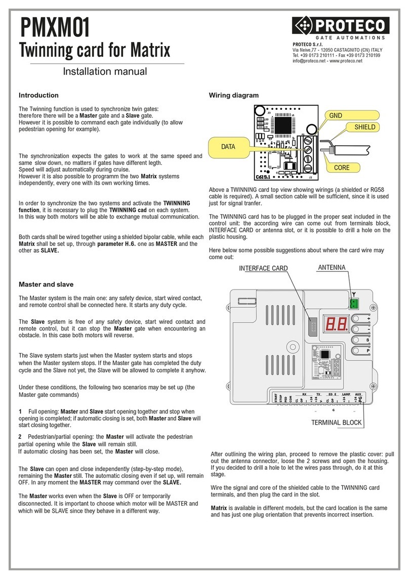
Proteco PMXM01 User manual

Proteco

Proteco PMXM01 User manual

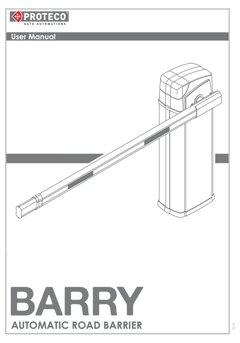
Proteco BARRY User manual

Proteco

Proteco BARRY User manual

Popular Control System manuals by other brands

Raven AccuBoom Parallel Installation Manual

Raven

Raven AccuBoom Parallel Installation Manual

GE Mark VIe System guide

GE

GE Mark VIe System guide

CAME G4040Z installation manual

CAME

CAME G4040Z installation manual

Data Aire dap4 touch user manual

Data Aire

Data Aire dap4 touch user manual

WAREMA Wisotronic installation instructions

WAREMA

WAREMA Wisotronic installation instructions

ShowPro K2 user manual

ShowPro

ShowPro K2 user manual

Pilz PSS67 IO1 16FDI operating manual

Pilz

Pilz PSS67 IO1 16FDI operating manual

Norac UC4+ Apache 1010 2005+ installation manual

Norac

Norac UC4+ Apache 1010 2005+ installation manual

Tigo TS4-R Installation & quick start guide

Tigo

Tigo TS4-R Installation & quick start guide

Neptune Systems EnergyBar 6 Setup guide

Neptune Systems

Neptune Systems EnergyBar 6 Setup guide

Siemens SINUMERIK 840D sl Programming manual

Siemens

Siemens SINUMERIK 840D sl Programming manual

BACHMANN EUROPE Plc E-Z COMMAND DIGITAL COMMAND CONTROL SYSTEM user manual

BACHMANN EUROPE Plc

BACHMANN EUROPE Plc E-Z COMMAND DIGITAL COMMAND CONTROL SYSTEM user manual

PMV P5 manual

PMV

PMV P5 manual

Reliance Foundry R-7651-EM Installation

Reliance Foundry

Reliance Foundry R-7651-EM Installation

OPTO 22 SNAP PAC MOTION CONTROL user guide

OPTO 22

OPTO 22 SNAP PAC MOTION CONTROL user guide

Eaton CCS 5 instruction manual

Eaton

Eaton CCS 5 instruction manual

Sutter Lambda VF-5 Operation manual

Sutter

Sutter Lambda VF-5 Operation manual

PACH & COMPANY AeGIS AFGR9 Installation and programming manual

PACH & COMPANY

PACH & COMPANY AeGIS AFGR9 Installation and programming manual

manuals.online logo
manuals.online logoBrands
  • About & Mission
  • Contact us
  • Privacy Policy
  • Terms and Conditions

Copyright 2025 Manuals.Online. All Rights Reserved.