2
TABLE OF CONTENTS
B680H BARRIER GATE OPERATOR
1. TECHNICAL SPECIFICATIONS ............................................................................................................................................................6
2. ELECTRICAL LAYOUT .........................................................................................................................................................................7
3. DIMENSIONS .........................................................................................................................................................................................7
4. INSTALLING THE OPERATOR..............................................................................................................................................................7
4.1 Preliminary checks .......................................................................................................................................................................7
4.2 Install the foundation plate..........................................................................................................................................................7
4.3 Mechanical installation ................................................................................................................................................................7
4.5 Balancing the Beam....................................................................................................................................................................12
5. MANUAL OPERATION ........................................................................................................................................................................12
5.1 Restore normal operations ........................................................................................................................................................12
6. POWER CONNECTION .......................................................................................................................................................................12
7. FIELD INSTALL LABELS ....................................................................................................................................................................13
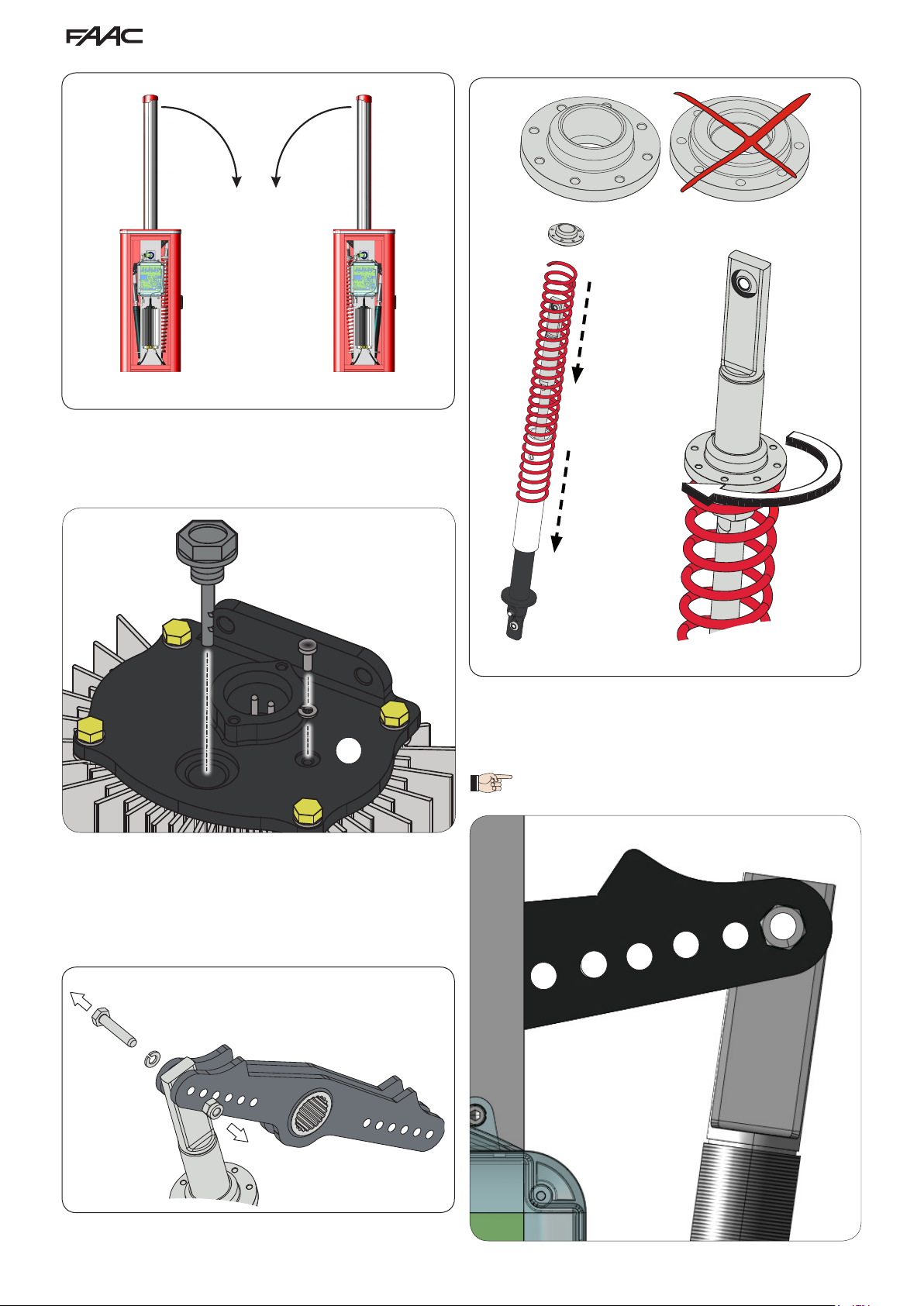
8. REVERSING THE OPENING DIRECTION ..........................................................................................................................................13
9. MAINTENANCE ...................................................................................................................................................................................13
8.1 Topping up the oil .......................................................................................................................................................................13
8.2 Air bleeding .................................................................................................................................................................................13
10. INSTALL THE BEAM LIGHTS ...........................................................................................................................................................14
11. INSTALL THE COVER .......................................................................................................................................................................15
12. SPARE PARTS ...................................................................................................................................................................................16
E680 CONTROL BOARD
1. WARNINGS ..........................................................................................................................................................................................18
2. DESCRIPTION OF THE COMPONENTS ............................................................................................................................................18
3. TECHNICAL SPECIFICATIONS ..........................................................................................................................................................18
4. ELECTRICAL CONNECTIONS............................................................................................................................................................19
4.1 Terminal board J1 (inputs) .........................................................................................................................................................19
4.2 Terminal board J2 (outputs).......................................................................................................................................................20
4.3 Terminal board J3 (external ashing lamp) .............................................................................................................................20
4.4 Terminal board J4 (loop detector) ............................................................................................................................................20
4.5 Connector J5 (Motor)..................................................................................................................................................................20
4.6 Connector J7 (Encoder).............................................................................................................................................................20
4.7 Connector J10 (Radio)................................................................................................................................................................20
4.8 Connector J11 (Beam break-out sensor) .................................................................................................................................20
4.9 Connector J12 (Emergency battery).........................................................................................................................................20
4.10 Connector J13 (36VDC Power Supply) ...................................................................................................................................20
4.11 Connector J15 (ashing trac light) ......................................................................................................................................20
4.12 Connector J16 (beam lights)....................................................................................................................................................21
5. PROGRAMMING..................................................................................................................................................................................21
5.1 Basic conguration.....................................................................................................................................................................21
5.2 Changing the predened parameters set ................................................................................................................................22
5.3 Default Selection Tables ............................................................................................................................................................23
6. Advanced Conguration ....................................................................................................................................................................24
6.1 Conguring the loop detector ...................................................................................................................................................25
6.2 Expert Conguration ..................................................................................................................................................................26
6.3 Pre-Dened Parameter Sets......................................................................................................................................................29
6.4 “Expert” default parameters .....................................................................................................................................................30
7. START-UP.............................................................................................................................................................................................30
7.1 Verifying the diagnostic LEDs ...................................................................................................................................................30
7.2 Setup.............................................................................................................................................................................................30
8. TESTING THE AUTOMATED SYSTEM ...............................................................................................................................................30
9. MASTER/SLAVE CONFIGURATION ...................................................................................................................................................31
10. INTERLOCK .......................................................................................................................................................................................32
11. OPERATING LOGICS TABLE............................................................................................................................................................33
B680H Rev. A October 2016