WaterGroup Econoflo EFCMINI-17SXT Operating instructions

Page 5 of this manual contains important maintenance procedures for
the continued proper operation of your unit. These MUST be performed
regularly for your guarantee to remain valid.
Econoflo MINI SXT
Automatic Meter Initiated Water Softener
Operating and Maintenance Manual
#54789 5/10

Hard water enters your home through the main supply line, enters the softener and passes down through a resin mineral bed
which softens the water. An ion exchange process takes place in which the resin beads capture and hold calcium and magnesium,
the hardness minerals, while the water takes on sodium ions. The soft water then flows into your household water line.
In normal operation, the Time of Day display will alternate being viewed with the Volume Remaining display. This display
will be in gallons, liters or cubic meters. As treated water is used, the Volume Remaining display will count down from a
maximum value to zero or (---). Once this occurs, a regeneration cycle will be initiated at the Set Regeneration Time. Water
flow through the valve is indicated by the Flow Indicator that will flash in direct relationship to flow rate.
833 Gallons of Treated
Water Remaining
0 Gallons of Treated
Water Remaining
In regeneration, the control will display a special regeneration display. In this display, the control will show the
current regeneration step number the valve is advancing to or has reached and the time remaining in that step. The
step number displayed will flash until the valve has completed driving into this regeneration step position. Once all
regeneration steps have been completed, the valve will return to Service and resume normal operation.
Less than 6 minutes
remaining in Regen
Step Rapid Rinse
Pushing the Extra Cycle Button during a regeneration cycle will immediately advance the valve to the next cycle step
position and resume normal step timing.
1
5
Performance
*Items include brine tank grid.
EFC indicate cabinet model, EFT indicate twin tank model
Maximum Water Temperature = 110°F (43°C)
Maximum Operating Pressure = 100 PSIG (689 kPa)
Voltage = 24V / 60 Hz (120V to 24V wall mount transformer included)
Pipe Size = 3/4”
• At the stated service flow rates, the pressure drop through these devices will not exceed
15 psig.
• Changing salt settings from factory setting may require changing injector sizes to
achieve stated capacities
• The manufacturer reserves the right to make product improvements which may deviate
from the specifications and descriptions stated herein, without obligation to change
previously manufactured products or to note the change.
Model Number
Pipe
Size
(Inches)
Flow Rates USGPM Capacity - Grains (ppm) Mineral
Tank Size
(Inches)
Installation Space
W x D x H
(Inches)
Salt
Capacity
(lbs.)
Shipping
Weight
(lbs.)
Service Backwash @ 3 lbs
/cu.ft
@ 6 lbs/
cu.ft
@ 12 lbs
/cu.ft
EFCMINI-17SXT 3/4" 10 2 5,500 8,500 17,000 10X18 13.5 x 22.5 x 27 75 40
EFCMINI-22SXT 3/4" 10 2 7,000 11,000 22,000 10X18 13.5 x 22.5 x 27 75 40
Please Note:
Attach the supplied overow tting and drain tubing at the
pre-drilled hole on the side of the softener cabinet.

The control will only enter the Program Mode with the valve in Service. While in the Program Mode, the control will
continue to operate normally, monitoring water usage and keeping all displays up to date. Control programming is stored
in memory permanently, eliminating the need for battery back-up power.
A meter immediate control measures water usage and regenerates the system as soon as the calculated system
capacity is depleted. The control calculates the system capacity by dividing the unit capacity (typically expressed in
grains/unit volume) by the feedwater hardness and subtracting the reserve. Meter Immediate systems generally do not
use a reserve volume. However, in twin tank systems with soft-water regeneration, the reserve capacity should be set
to the volume of water used during regeneration to prevent hard water break-through. A Meter Immediate control will
also start a regeneration cycle at the programmed regeneration time if a number of days equal to the regeneration day
override pass before water usage depletes the calculated system capacity.
A Meter Delayed Control measures water usage and regenerates the system at the programmed regeneration time after
the calculated system capacity is depleted. As with Meter Immediate systems, the control calculates the system capacity
by dividing the unit capacity by the feedwater hardness and subtracting the reserve. The reserve should be set to insure
that the system delivers treated water between the time the system capacity is depleted and the actual regeneration
time. A Meter Delayed control will also start a regeneration cycle at the programmed regeneration time if a number of
days equal to the regeneration day override pass before water usage depletes the calculated system capacity.
A Time Clock Delayed Control regenerates the system on a timed interval. The control will initiate a regeneration cycle
at the programmed regeneration time when the number of days since the last regeneration equals the regeneration day
override value.
This control regenerates the system on a weekly schedule. The schedule is defined in Master Programming by setting
each day to either “off” or “on.” The control will initiates a regeneration cycle on days that have been set to “on” at the
specified regeneration time.
The SXT includes integral power backup. In the event of power failure, the control shifts into a power-saving mode. The
control stops monitoring water usage, and the display and motor shut down, but it continues to keep track of the time
and day for a minimum of 48 hours.
The system configuration settings are stored in a non-volatile memory and are stored indefinitely with or without line
power. The Time of Day flashes when there has been a power failure. Press any button to stop the Time of Day from
flashing.
If power fails while the unit is in regeneration, the control will save the current valve position before it shuts down. When
power is restored, the control will resume the regeneration cycle from the point where power failed. Note that if power
fails during a regeneration cycle, the valve will remain in it’s current position until power is restored. The valve system
should include all required safety components to prevent overflows resulting from a power failure during regeneration.
The control will not start a new regeneration cycle without line power. If the valve misses a scheduled regeneration
due to a power failure, it will queue a regeneration. Once power is restored, the control will initiate a regeneration cycle
the next time that the Time of Day equals the programmed regeneration time. Typically, this means that the valve will
regenerate one day after it was originally scheduled. If the treated water output is important and power interruptions are
expected, the system should be setup with a sufficient reserve capacity to compensate for regeneration delays.
The MINI-22 Softener can be used for ferrous iron removal from water. The iron removal will depend on inlet water
chemistry. Make sure that the pH<6.5 and there are no oxidants in the water. The MINI-22 is not recommended to
be used on ferric iron. Use of resin cleaning and backwashing may be periodically required. This unit will not remove
organically bound iron and iron bacteria. To get an affective removal of iron, use the upflow configuration and high salt
dosages (12 lbs/salt/CF of resin).
Please consult your water treatment dealer before applying this softener for iron removal purposes.
2

3
All government codes and regulations governing the installation of these devices must be observed.
If the ground from the electrical panel or breaker box to the water meter or underground copper pipe is
tied to the copper water lines and these lines are cut during installation of the Noryl bypass valve and/or poly pipe, an
approved grounding strap must be used between the two lines that have been cut in order to maintain continuity. The
length of the grounding strap will depend upon the number of units being installed and/or the amount of copper pipe
being replaced with poly. See Figure 1.
In all cases where metal pipe was originally used and is
later interrupted by poly pipe or the Noryl bypass valve
as in Figure 1 or by physical separation as in Figure 2,
an approved ground clamp with no less than #6
copper
conductor must be used for continuity,
to maintain proper
metallic pipe bonding.
Check your local electrical code for the correct clamp and
cable size.
1. Determine the best location for your water softener,
bearing in mind the location of your water supply lines,
drain line and 120 volt AC electrical outlet. Subjecting
the softener to freezing or temperatures above 110°F
(43°C) will void the warranty.
• Remove the valve from the mineral tank.
• Temporarily plug the open end of the riser tube to ensure
that no resin or gravel falls down into the distribution.
• Fill mineral tank one quarter full of water to protect
distribution during gravel installation.
• Slowly and carefully add the gravel support bed and the
softener or filtration media leveling each layer as it is
placed into the tank.
• Unplug the riser tube, carefully position the valve over it and turn the valve into the threads in the fiberglass tank,
tightening securely into tank. Note: Ensure that the internal O-ring in the valve fits securely over the riser tube.
Silicone grease (#13691) or other food grade lubricant may be applied to the O-ring to ease installation of the riser
tube. DO NOT use petroleum based lubricants as they will cause swelling of O-ring seals.
• The softener or filter is now charged with softening resin.
• It is recommended that the softener or filter tank now be completely filled with water (SLOWLY) to soak the resin
or filtration media before startup. This will allow the media to absorb water as well as help displace any trapped
air. This will reduce the chance of backwashing resin or filter media out of the tank during the initial backwash on
startup.
2. Outside faucets used to water lawns and gardens should not supply softened water. A new water line is often
required to be connected to supply hard water to the inlet of the water softener and to the outside faucets. Cut the
water line between where it enters the house and before any lines that branch off to feed the hot water heater or
other fixtures in the house and as near the desired location of the water softener as possible. Install a tee fitting
on the feed end of the cut pipe, and an elbow fitting on the other end. Install piping from the tee to the inlet of the
water softener and from the elbow to the outlet of the softener. To sever the water lines which branch off to feed
any outside faucets, cut the branch lines approximately two inches from the fitting on the main water line. Install an
elbow on the end of the pipe nearest the outside faucet and a cap on the end connected to the existing water line.
Install piping from the tee installed on the inlet line to the water softener to the elbow installed on the pipe to the
outside faucet. Following this procedure will result in all lines in the house, with the exception of the outside faucets,
but including the water heater and therefore the hot water lines, being supplied with soft water.
Electrical Panel
Ground Strap
Poly Pipe
Ground
From
Panel
Poly Pipe
Softener
c/w Plastic Bypass
Copper Pipe
Water Meter
Outside Water Line For Outside & 3rd Tap Comes From Meter
Filtered Water Line in Home
Unfiltered Water Bypass
Loop Cut & Capped
Ground Strap Required
Because of Break in Continuity

4
3. Familiarize yourself with the location of the inlet, outlet and drain on the control valve. Be very careful not to get the
controls wet.
4. Attach the bypass valve to the control valve. Connect the inlet and outlet of the water softener to the plumbing in the
house. The control valve must not be submitted to temperatures above 71°C (110°F). When sweat fittings are used,
to avoid damaging the control valve, solder the threaded copper adapters to the copper pipe and then, using Teflon
tape, screw the assembly into the bypass valve.
do not use pipe thread compound as it may attack the material in the valve body.
5. Using teflon tape, screw the 1/2” hose barb into the drain port in the valve. Attach 1/2” drain hose to the hose
barb and tighten securely with a hose clamp. Run the drain line to a floor drain or a laundry drain. Complete any
necessary plumbing.
6. Install overflow fitting and connect the drain tubing.
7. On twin tank units, pull the 3/8” brine line through the hole in the back of the brine tank. Connect the brine line to the
fitting on the side of the valve using the nut and ferrule. Tighten snugly.
8. Make sure the bypass valve is in the service position.
9. Plug the 24-volt transformer into a 120 VAC 60 Hz outlet. This valve has four positions: 1) Backwash 2) Brine/Rinse
3) Rapid Rinse and 4) Brine Refill. When the valve is in the Service position, the extra cycle button (far left button
as shown on Figure 4) must be pressed and held for 5 seconds before it activates. Press and hold the extra cycle
button for 5 seconds to advance the valve into the “1” Backwash position. Slowly turn on the water supply and allow
the unit to backwash until the air purges out of the tank and clears the system.
10. Press the extra cycle button to advance the valve to the “2” position. Press once more to advance to the “3” position.
Press once more to advance to the “4” Brine refill position. Wait until the water level reaches 6” in the brine tank.
Water can be added to the tank to speed up the filling but the valve should be in the Brine Refill position for a
minimum of two minutes to purge the air out of the injector set.
11. Press the extra cycle button to advance the valve from the Brine Fill position through service to the “2” position
Brine/Rinse position. Verify that water is being drawn from the tank. If not, repeat step 9.
12. Press the extra cycle button to advance the valve to the “3” Rapid Rinse position and allow water to run to drain for
2 minutes.
13. Press the extra cycle button to advance the valve to the “4” Brine Fill position until there is 6” of water in the brine
tank. Press the extra cycle button to advance the valve back into the service position indicated by the red dot in
upper left corner of the display.
14. Put 40 kgs of crystal water softener salt in the brine tank. The unit will automatically fill to the correct level when it
regenerates.
We recommend that all new water conditioners be disinfected as part of the startup.
Sanitization is achieved by the application of chlorine in the regeneration cycle of the conditioner. A liquid solution of
5.25% sodium hypochlorite (commonly referred to as household bleach) is recommended as a suitable disinfectant. Use
only unscented products. For every cubic foot of resin in the softener, pour approximately two (2) tablespoons of sodium
hypochlorite into the brine well tube. The brine tank refill in Step 12 should add the correct amount of water to the
brine tank. If not, the water can be added manually now. Press and hold the EXTRA CYCLE button to begin a manual
regeneration. Press the EXTRA CYCLE button again to advance the valve to the Brine/Rinse position. Allow softener to
complete the Brine/Rinse cycle, then let the manual regeneration continue until the brine tank is refilled again with the
correct amount of water.

5
The valve has been pre-programmed with factory settings as follows:
6 lbs of salt/
CF of resin 3 lbs of salt/ 12 lbs of salt/
(Factory Set) CF of resin CF of resin
1. Backwash ....................... 5 minutes .................................3 minutes ............................. 10 minutes
2. Brine Rinse ..................... 30 minutes ................................8 minutes ............................. 60 minutes
3. Rapid Rinse .................... 5 minutes .................................3 minutes ............................. 10 minutes
4. Brine Refill ...................... 8 minutes .................................4 minutes ............................. 16 minutes
Whenever the valve is in Service the current time of day can be set, the control programmed, or an extra regeneration
initiated at any time.
1. Press and hold either the Up or Down buttons until the programming icon replaces the service icon and the
parameter display reads TD.
2. Adjust the displayed time with the Up and Down buttons.
3. When the desired time is set, press the Extra Cycle button to resume normal operation. The unit will also return to
normal operation after 5 seconds if no buttons are pressed.
1. Press the Extra Cycle button. The service icon will flash to indicate that a regeneration is queued.
2. To cancel a queued regeneration, press the Extra Cycle button.
Press and hold the Extra Cycle button for five seconds.

6
1. Press the Up and Down buttons for five seconds while in service,
and the time of day is NOT set to 12:01 PM.
2. Use this display to adjust the Day Override. This option setting is
identified by “DO” in the upper left hand corner of the screen.
3. Press the Extra Cycle button. Use this display to adjust the
Regeneration Time. This option setting is identified by “RT” in the
upper left hand corner of the screen.
4. Press the Extra Cycle button. Use this display to adjust the Feed Water Hardness. This option setting is identified by
“FH” in the upper left hand corner of the screen.
In order to calculate the Total Water Hardness, assume that the water softener (MINI-22) is being applied to a
water supply that not only requires the removal of hardness, but also of some iron as well. Before the regeneration
frequency can be set, the compensated total hardness must be calculated to factor in the iron that will be removed
as well. To do this, you must have the results of water analysis that provides the Total Hardness in GPG (grains/
USGallon) and Iron which is usually recorded as ppm (parts per million) or mg/L (milligrams per litre).
eg. Total Hardness = 25 GPG & Iron = 2 mg/L
therefore;
Compensated Hardness = 25 GPG + 4 x 2 mg/L = 33 GPG
Note: If Total Hardness has been recorded as ppm (or mg/L) in testing, divide the number by 17.1 to obtain the
Total Hardness expressed in GPG.
DO Day Override The timer’s day override setting
RT Regeneration Time The time of day that the system will regenerate (meter delayed, timeclock,
and day-of-week systems)
H Feed Water Hardness The hardness of the inlet water - used to calculate system capacity for
metered systems
RC Reserve Capacity The fixed reserve capacity
CD Current Day The current day of week

7
Note: Error codes appear on the In Service display
NOTE: Unit will flash when an error exists.
[Err 0]
[Err 1]
[Err 2]
[Err 3]
Drive motor is stalled
Drive motor is running continuously
There have been more than 99 days since
the last Regeneration. If the Day of the
Week mode of regeneration is selected
and days since last regeneration exceeds
7 days.
[ 7 - - 5 ]: There have been more than
7 days since the last regeneration. All
individual settings (d1, d2, d3, d4, d5, d6,
d7) are set to 0.
Control board memory failure.
Unplug the unit from the power source
When power is restored to the unit, the Err _ display
code clears. If the condition causing the error has
not been resolved the Err _ code reappears in the
four digit display. Do not attempt to troubleshoot this
problem any further.
Regeneration must occur for the unit to recover, the
display to clear and the valve to
function normally.
[ 7 - - 5 ]: To recover from [Err2], the user must
initiate a regeneration or set at least one individual
day to 1.
Perform a Master Reset. If the error returns,
do not attempt to troubleshoot this problem any
further.
5. Press the Extra Cycle button. Use this display to adjust the Fixed Reserve Capacity. This option setting is identified
by “RC” in the upper left-hand corner of the screen.
75 gallons X # of people in the house = RC
6. Press the Extra Cycle button. Use this display to set the Current Day of the Week. This option setting is identified by
“CD” in the upper left hand corner of the screen. This option is only available after the Day of the Week control
is set to ‘ON’ in the Master Programming. Refer to the valve manual for details.
7. Press the Extra Cycle button to end User Programming Mode.
1 75
2 150
3 225

8
If you run out of softened water because of inadequate regeneration frequency, inadequate reserve capacity, power
failure or unusually high water usage, you can initiate a manual regeneration simply by pressing the extra cycle button.
The softener will now automatically complete a regeneration cycle and return to service. If possible, avoid water use
during the regeneration cycle.
Once you have set your softener and you experience frequent loss of water pressure, you may have to increase the
frequency of regeneration by resetting the gallons between regeneration.
The regeneration cycle lasts approximately 2-1/2 hours, after which soft water service will be restored. During
regeneration, hard water is automatically bypassed for use in the household. Hot water should be used as little as
possible during this time to prevent hard water from filling the water heater. This is why the automatic regeneration is set
for sometime during the night and manual regenerations should be performed when little or no water will be used in the
household.
The brine tank is equipped with a safety float which prevents your brine tank from over filling as a result of a malfunction
such as a power failure.
Your softener is designed to operated under normal water pressures from 20 psi (1.4 atm) to 100 psi (8.2 atm).
You may notice new sounds as your water softener operates. The regeneration cycle lasts approximately 48 minutes.
During this time, you may hear water running intermittently to the drain.
In case of an emergency such as an overflowing brine tank, you can isolate
your water softener from the water supply using the bypass valve located at
the back of the control.
In normal operation the bypass is open with the ON/OFF knobs in line with
the INLET and OUTLET pipes. To isolate the softener, simply rotate the
knobs clockwise (as indicated by the word BYPASS and arrow) until they
lock.
You can use your water related fixtures and appliances as the water supply
is bypassing the softener. However, the water you use will be hard.
To resume soft water service, open the bypass valve by rotating the knobs
counter-clockwise.
OUTLET
INLET

9
Check the salt level monthly. Remove the lid from the cabinet or brine tank, make sure salt level is always above the
brine level (you should not be able to see water).
Use only clean salt labeled for water conditioner use, such as crystal, pellet, nugget, button or solar.
The use of rock salt is discouraged because it contains insoluble silt and sand which build up in the brine tank and can
cause problems with the system’s operation.
Add the salt directly to the tank, filling no higher than the top of the brine well.
Liquid brine will irritate eyes, skin and open wounds - gently wash exposed area with fresh water. Keep children away
from your water conditioner.
Humidity or the wrong type of salt may create a cavity between the water and the salt.
This action, known as “bridging”, prevents the brine solution from being made, leading to
your water supply being hard.
If you suspect salt bridging, carefully pound on the outside of the plastic brine tank
or pour some warm water over the salt to break up the bridge. This should always
be followed up by allowing the unit to use up any remaining salt and then thoroughly
cleaning out the brine tank. Allow four hours to produce a brine solution, then manually
regenerate the softener.
To retain the attractive appearance of your new water softener, clean occasionally with
a mild soap solution. Do not use abrasive cleaners, ammonia or solvents. Never subject
your softener to freezing or to temperatures above 110°F (43°C).
Sediment, salt and silt will restrict or clog the injector. A clean water
supply and pure salt will prevent this from happening.
The injector assembly is located on the right side of the control valve.
This assembly is easy to clean.
Shut off the water supply to your softener and reduce the pressure by
opening a cold soft water faucet. Using a screwdriver, remove the two
screws holding the injector cover to the control valve body. Carefully
remove the assembly and disassemble as shown in Figure 7. The
injector orifice is removed from the valve body by carefully turning
it out with a screwdriver. Remove the injector throat the same way.
Carefully flush all parts including the screen. Use a mild acid such
as vinegar or Pro-Rust Out to clean the small holes in the orifice and
throat.
Reassemble using the reverse procedure.
An approved resin cleaner MUST be used on a regular basis if your water supply contains iron. The amount of resin
cleaner and frequency of use is determined by the quantity of iron in your water (consult your local representative or
follow the directions on the resin cleaner package).
INJECTOR BODY
INJECTOR THROAT
INJECTOR NOZZLE
“O” RING
INJECTOR COVER
INJECTOR SCREEN
SCREW

10
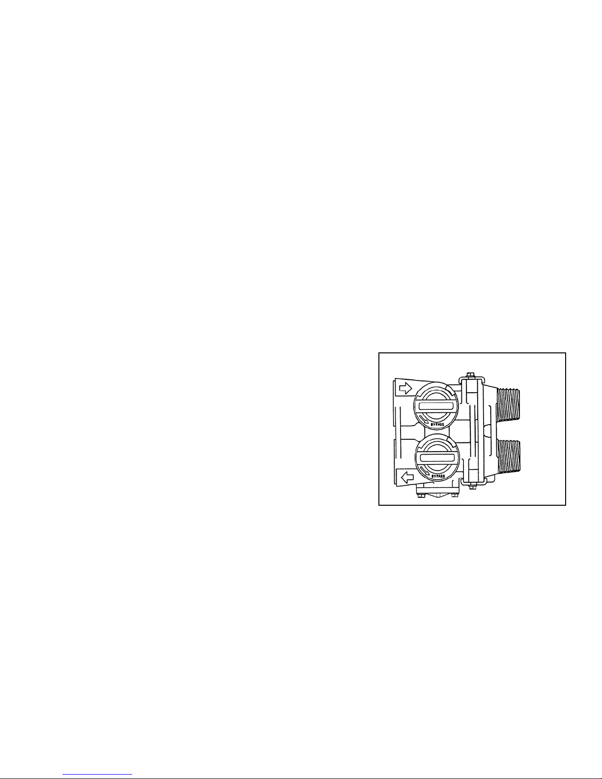
A. Bypass valve is open
B. No salt in brine tank
C. Injector or screen plugged
D. Insufficient water flowing into brine tank
E. Hot water tank hardness
F. Leak at distributor tube
G. Internal valve leak
H. Flow meter jammed
I. Flow meter cable disconnected or not plugged into
meter cap
J. Improper programming
A. Close bypass valve
B. Add salt to brine tank and maintain salt level above water level
C. Replace injectors and screen
D. Check brine tank fill time and clean brine line flow tank control if plugged
E. Make sure distributor tube is not cracked. Check O ring and tube pilot
F. Make sure distributor tube is not cracked. Check O ring and tube pilot
G. Replace seals and spacers and/or piston
H. Remove obstruction from flow meter
I. Check meter cable connection to timer and meter cap
J. Reprogram the control to the proper regeneration type, inlet water hardness, capacity or
flow meter size.
A. Electrical service to unit has been interrupted
B. Timer is not operating properly
C. Defective valve drive motor
D. Improper programming
A. Assure permanent electrical service (check fuse, plug, chain or switch)
B. Replace timer
C. Replace drive motor
D. Check programming and reset as needed
A.Improper salt setting
B. Excessive water in brine tank
C. Improper programming
A. Check salt usage and salt setting
B. See #7
C. Check programming and reset as needed
A. Iron build-up in line to water conditioner
B. Iron build-up in water conditioner
C. Inlet of control plugged due to foreign material
broken loose from pipes by recent work done on
plumbing system.
A. Clean line to water conditioner
B. Clean control and add resin cleaner to resin bed. Increase frequency of regeneration
C. Remove piston and clean control
A. Air in water system
B. Drain line flow control is too large
A. Assure that well system has proper air eliminator control. Check for dry well condition.
B. Ensure drain line flow control is sized
A. Fouled resin bed
B. Iron content exceeds recommended parameters
A. Check backwash, brine draw and brine tank fill. Increase frequency of regeneration.
Increase backwash time.
B. Add iron removal filter system
A. Plugged drain line flow control
B. Brine valve failure
C. Improper programming
A. Clean flow control
B. Replace brine valve
C. Check programming and reset as needed
A. Plugged injector system
B. Timer not operating properly
C. Foreign material in brine valve
D. Foreign material in brine line flow control
E. Low water pressure
F. Improper programming
A. Clean injector and replace screen
B. Replace timer
C. Clean or replace brine valve
D. Clean brine line flow control
E. Raise water pressure
F. Check programming and reset as needed
A. Drain line flow control is plugged
B. Injector is plugged
C. Injector screen is plugged
D. Line pressure is too low
E. Internal control leak
F. Improper programming
G. Timer not operating properly
A. Clean drain line flow control
B. Clean or replace injectors
C. Replace screen
D. Increase line pressure (line pressure must be at least 20 psi at all times)
E. Change seals and spacers and/or piston assembly
F. Check programming and reset as needed
G. Replace timer
A. Timer not operating properly
B. Faulty microswitches and/or harness
C. Faulty cycle cam operation
A. Replace timer
B. Replace faulty microswitch or harness
C. Replace cycle cam or reinstall
A. Foreign material in control
B. Internal control leak
C. Control valve jammed in brine or backwash position
D. Timer motor stopped or jammed teeth
E. Timer not operating properly
A. Remove piston assembly and inspect bore. Remove foreign material and check control
in various regeneration positions
B. Replace seals and/or piston assembly
C. Replace piston and seals and spacers
D. Replace timer motor and check all gears for missing teeth
E. Replace timer

Econoflo Guarantee
WaterGroup Inc. guarantees that your new water conditioner is built of quality material and workmanship.
When properly installed and maintained, it will give years of trouble free service.
WaterGroup Inc. will replace any part which fails within 60 months from date of manufacture, as indicated
by the serial number provided the failure is due to a defect in material or workmanship. The only exception
shall be when proof of purchase or installation is provided and then the warranty period shall be from the date
thereof.
WaterGroup Inc. will provide a replacement mineral tank or brine tank to any original equipment purchaser in
possession of a tank that fails within 120 months, provided that the water conditioner is at all times operated in
accordance with specifications and not subject to freezing.
WaterGroup Inc. assumes no responsibility for consequential damage, labor or expense incurred as a result of
a defect or for failure to meet the terms of these guarantees because of circumstances beyond its control.
WATERGROUP INC. WATERGROUP COMPANIES INC.
FRIDLEY, MN REGINA, SK • CAMBRIDGE, ON
1-800-354-7867 1-877-288-9888
www.watergroup.com
This manual suits for next models
2
Table of contents
Other WaterGroup Water Dispenser manuals