WaterGroup 6200 SXT Service manual

Made in Canada
6200 SXT Automatic Meter Initiated
Carbon Mixed Bed Water Softener
Operating and Service Manual

1
Read this Manual First
• Read this manual thoroughly to become familiar with the device and its capabilities before installing or operating your
Water Softener. Failure to follow instructions in this manual could result in personal injury or property damage. This manual
will also help you to get the most out of your softener.
• This system and its installation must comply with state and local regulations. Check with your local public works depart-
ment for plumbing and sanitation codes. In the event the codes conflict with any content in this manual the local codes
should be followed. For installations in Massachusetts, Massachusetts Plumbing Code 248 CMR shall be adhered to. Con-
sult your licensed plumber for installation of this system.
• This water softener is designed to operate on pressures of 20 psig 125 psig. If the water pressure is higher than the maxi-
mum use a pressure reducing valve in the water supply line to the softener.
• This unit is capable of operating at temperatures between 40°F and 110°F (4°C - 43°C). Do not use this water softener on
hot water supplies.
• Do not install this unit where it may be exposed to wet weather, direct sunlight, or temperatures outside of the range
specified above.
• Do not use water that is microbiologically unsafe without adequate disinfection before or after this system.
• This publication is based on information available when approved for printing. Continuing design refinement could cause
changes that may not be included in this publication. WaterGroup reserves the right to change the specifications referred
to in this literature at any time, without prior notice.
Safety Messages
Watch for the following safety messages in this manual:
NOTE: used to emphasize installation, operation or maintenance information which is important but does not
present a hazard.
Example: NOTE: Check and comply with you state and local codes. You must follow these guidelines.
CAUTION: used when failure to follow directions could result in damage to equipment or property.
Example:
CAUTION! Disassembly while under pressure can result in flooding.
WARNING: used to indicate a hazard which could cause injury or death if ignored.
Example:
WARNING! ELECTRICAL SHOCK HAZARD! UNPLUG THE UNIT BEFORE REMOVING THE COVER OR ACCESSING
ANY INTERNAL CONTROL PARTS
NOTE: Do not remove or destroy the serial number. It must be referenced on request for
warranty repair or replacement
Introduction

2
How Your Water Conditioner Works
Why Water Gets Hard And How It Is Softened
All of the fresh water in the world originally falls as rain, snow, or sleet. Surface water is drawn upward by the sun, forming
clouds. Then, nearly pure and soft as it starts to fall, it begins to collect impurities as it passes through smog and dust-laden
atmosphere. And as it seeps through soil and rocks it gathers hardness, rust, acid, unpleasant tastes and odors.
Water hardness is caused primarily by limestone dissolved from the earth by rainwater. Because of this, in earlier times
people who wanted soft water collected rainwater from roofs in rain barrels and cisterns before it picked up hardness from
the earth.
Some localities have corrosive water. A softener cannot correct this problem and so its printed warranty disclaims liability for
corrosion of plumbing lines, fixtures or appliances.
Iron is a common water problem. The chemical/physical nature of iron found in natural water supplies is exhibited in four
general types:
1. Dissolved Iron—Also called ferrous or “clear water” iron. This type of iron can be removed from the water by the
same ion exchange principle that removes the hardness elements, calcium and magnesium. Dissolved iron is solu-
ble in water and is detected by taking a sample of the water to be treated in a clear glass. The water in the glass
is initially clear, but on standing exposed to the air, it may gradually turn cloudy or colored as it oxidizes.
2. Particulate Iron—Also called ferric or colloidal iron. This type of iron is an undissolved particle of iron. A softener will
remove larger particles, but they may not be washed out in regeneration effectively and will eventually foul the
ion exchange resin. A filtering treatment will be required to remove this type of iron.
3. Organic Bound Iron—This type of iron is strongly attached to an organic compound in the water. The ion exchange
process alone cannot break this attachment and the softener will not remove this type of iron.
4. Bacterial Iron—This type of iron is protected inside a bacteria cell. Like the organic bound iron, it is not removed by
a water softener.
When using a softener to remove both hardness and dissolved iron it is important that it regenerates more frequently than
ordinarily would be calculated for hardness removal alone. Although many factors and formulas have been used to deter-
mine this frequency, it is recommended that the softener be regenerated when it has reached 50–75% of the calculated
hardness alone capacity. This will minimize the potential for bed fouling.
If you are operating a water softener on clear water iron, regular resin bed cleaning is needed to keep the bed from coat-
ing with iron. Even when operating a softener on water with less than the maximum of dissolved iron, regular cleanings
should be performed. Clean every six months or more often if iron appears in your conditioned water supply. Use resin bed
cleaning compounds carefully following the directions on the container.
CAUTION! Do not use where the water is microbiologically unsafe or with water of unknown quality without
adequate disinfection before or after the unit.

3
Specification
• At the stated service flow rates, the pressure drop through these devices will
not exceed 15 psig.
• Changing salt settings from factory setting may require changing injector
sizes to achieve stated capacities
How a WaterGroup Mixed Bed Water Softener Works
Water softeners remove hardness in the water by exchanging particles in the water, or ions. They remove hard ions the
calcium and magnesium in the water by trading it for sodium ions producing soft water. Unlike the calcium and magnesium,
sodium stays dissolved in water and does not form a scale. Sodium also does not interfere with the cleaning action of soaps.
The sodium is released by a charged resin contained in the softener, this resin also traps the calcium and magnesium ions.
Eventually this resin releases all of its sodium and has filled up with other ions, so it then must be regenerated. Regeneration
is accomplished by washing the resin with a salt saturated brine solution that removes the calcium and magnesium while
replenishing the sodium. This is why the softener requires a brine tank and salt.
The water softener can run for days before running out of sodium, and when it does, the sodium is replenished
in only a matter of a few hours.
The mixed bed softener also has activated carbon which adsorbs unpleasant taste and odor frm water which is caused due
to chlorine and organics. In normal operation, the Time of Day display will alternate being viewed with the Volume Remaining
display. This display will be in gallons or liters. As treated water is used, the Volume Remaining display will count down from a
maximum value to zero or (---). Once this occurs, a regeneration cycle will be initiated at the Set Regeneration Time. Water
flow through the valve is indicated by the Flow Indicator that will flash in direct relationship to flow rate.
Example 833 Gallons of Treated
Water Remaining
0 Gallons of Treated
Water Remaining
Timer Behavior During Regeneration
In regeneration, the control will display a special regeneration display. In this display, the control will show the current
regeneration step abbreviation the valve is advancing to or has reached and the time remaining in that step. The step
abbreviation displayed will flash until the valve has completed driving into this regeneration step position. Once all
regeneration steps have been completed, the valve will return to Service and resume normal operation.
Example Less than 6 minutes
remaining in Regeneration
Step Rapid Rinse
Pushing the during a regeneration cycle will immediately advance the valve to the next cycle step position and
resume normal step timing.
Please see the control valve manual for different regeneration step abbreviations.
PM Indicator
PM Indicator
Flow Indicator
(Flashing with water flow)
Flow Indicator
(Flashing with water flow)
5Regeneration Step
Abbreviation
* For Municipal Chlorinated Water Supplies Only
Working Temperature = 34-110°F (1-43°C)
(Do not subject the unit to freezing temperatures)
Working Pressure = 20-125 PSIG (137-861 kPa)
Voltage = 120V / 60 Hz
Pipe Size = 3/4”
Unit †
Item # Model #
Tank
Size Media (CF)
Service
Flow Rate
(gpm)
Backwash
Flow Rate
(gpm)
Brine Tank
Dimension
(W X D X H) in.
Salt
Capacity
(lbs)
Shipping
Weight
(lbs)
Mixed Bed Softener - Taste and Odor*
4932 MXC75 9 x 35 0.75 8 1.5 21 X 36 224 85
4933 MXC10 10 x 35 1 9 2 21 X 36 224 100
4934 MXC125 10 X 47 1.25 9 2 21 X 36 308 140
4935 MXC20 12 X 52 2 12 3 23 X 38 308 190
4936 MXC30 14 X 65 3 15 4 23 X 38 308 230
CAUTION! This Softener should only be used for Municipal Water Supplies.
• The manufacturer reserves the right to make product improvements which
may deviate from the specifications and descriptions stated herein, without
obligation to change previously manufactured products or to note the change.
* Do not use water that is microbiologically unsafe without adequate
disinfection before or after the system.
* Iron content must not exceed 1 ppm. Beyond 1 ppm an iron softener must be
used. Periodic media cleaning is required by
Pro-Res Cleaner is iron level exceed 0.3 ppm
† USA customers will need to add “-4” to the item numbers for ordering.
4
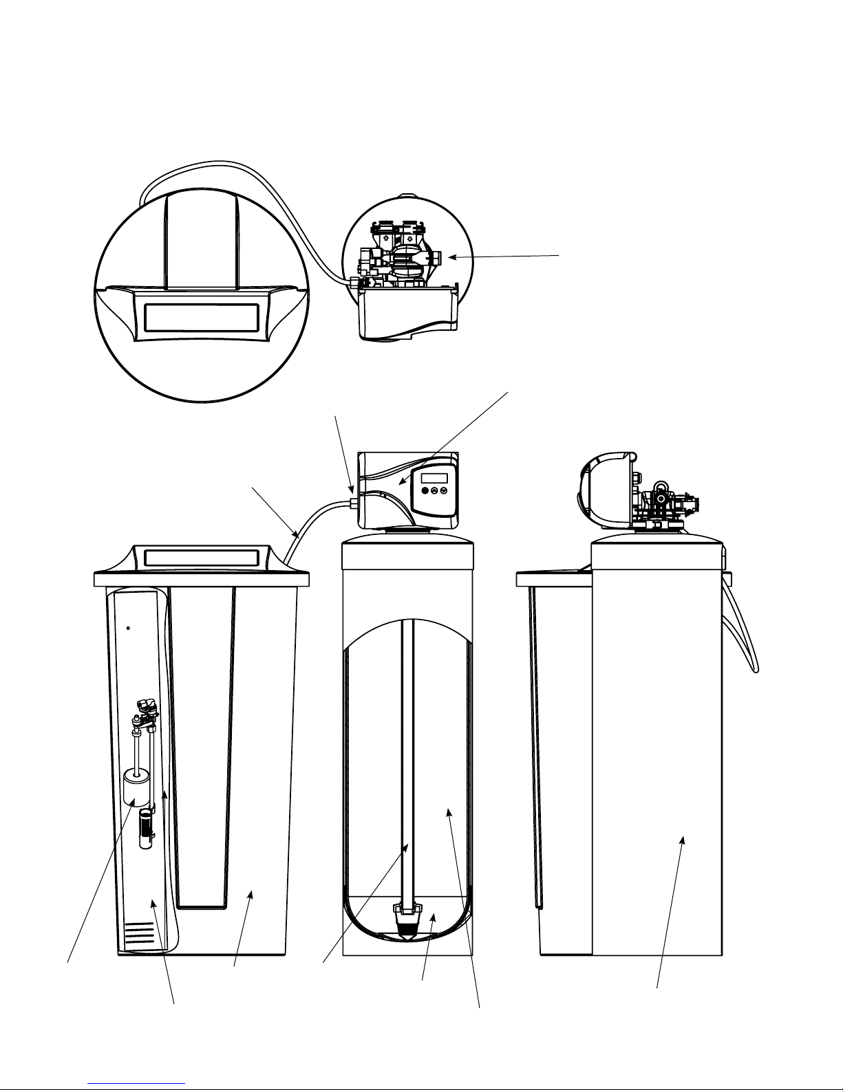
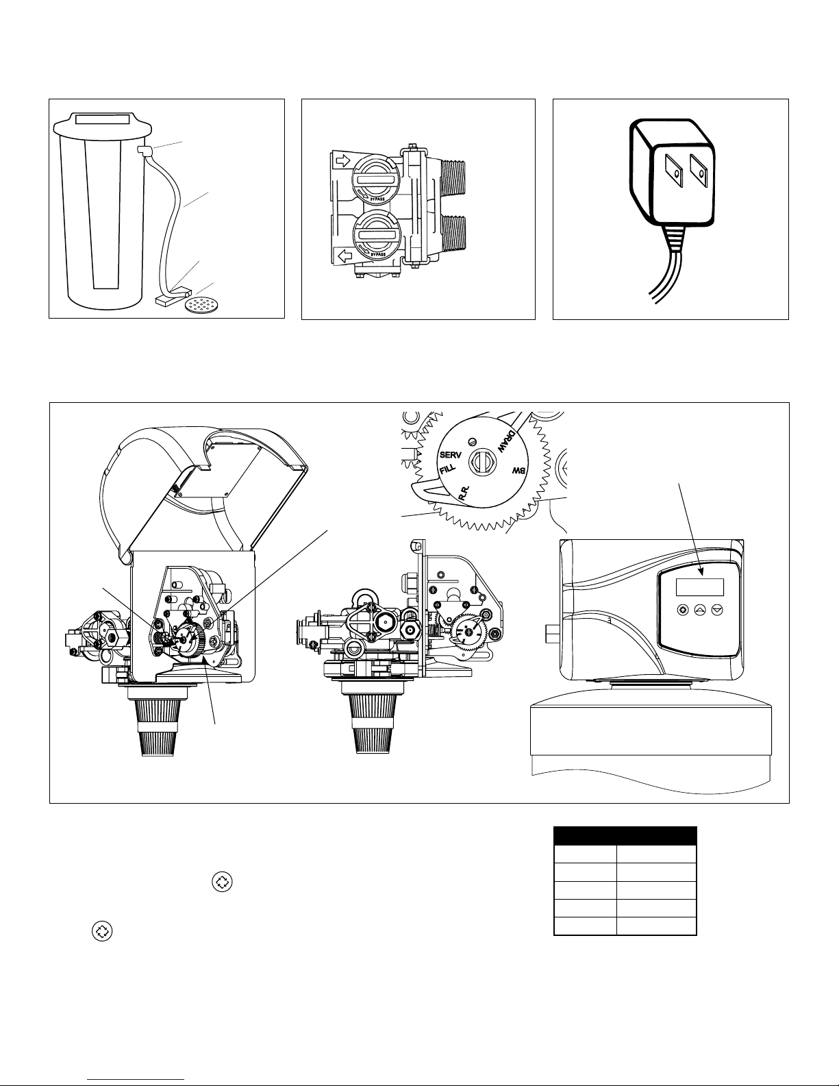
Familiarize Yourself with the Unit and Components
Distributor/Riser
Brine Well
Brine Tank
Media Bed
Underbed
Brine Tube
Control Valve
Brine Line
Connection
to Valve
Drain Line
Connection
to Valve
Safety Float/Air
Check Inside Mineral/Resin
Tank wrapped
with Jacket

5
Installation Instructions
Check your water hardness. Use test strips (Part # 2793828-20) to get an estimation of water hardness and contact your lo-
cal distributor to use WaterGroup laboratory for complete water analysis free of cost and no obligation to you.
All government codes and regulations governing the installation of these devices must be observed.
.
If the ground from the electrical panel or breaker box to the water meter or underground copper pipe is tied
to the copper water lines and these lines are cut during installation of the Noryl bypass valve and/or poly
pipe, an approved grounding strap must be used between the two lines that have been cut in order to main-
tain continuity. The length of the grounding strap will depend upon the number of units being installed and/or
the amount of copper pipe being replaced with plastic pipe. See Figure 1.
In all cases where metal pipe was originally used and is later interrupted by poly pipe or the Noryl bypass valve as in Figure
1 or by physical separation as in Figure 2, an approved ground clamp with no less than #6 copper conductor must be used
for continuity, to maintain proper metallic pipe bonding.
NOTE: Check your local electrical code for the correct clamp.
Figure 2
Filtered Water Line in Home
Unfiltered Water Bypass
Loop Cut & Capped
Ground Strap Required
Because of Break in Continuity
Figure 1
Electrical Panel
Hard
Filtered
Water Cold Soft Water
Hard Soft Water
Water Heater
Mixed Bed Water Softener
Drain
Filter
Ground Strap
Water Meter
Raw Water
To Outdoors
Drain

6
1. Determine the best location for your water softener,
bearing in mind the location of your water supply lines,
drain line and 120 volt AC electrical outlet. Subjecting the
softener to freezing or temperatures above 43°C (110°F)
will void the warranty.
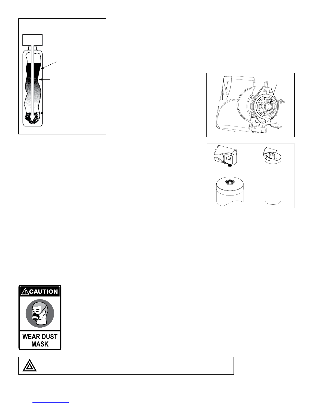
2. Media Installation (When Necessary). Models including
and higher than 1.5 CF of media are shipped with sepa-
rate media in pails or boxes. Models lower than 1.5 CF of
media come loaded with media and this step can be
skipped for new installation.
a) Remove the valve from
the mineral tank.
b) Temporarily plug the open end
of the riser tube to ensure that no
resin or gravel falls down into the
distribution.
The riser (distributor) remains
inside the tank seated in the
depression at the bottom.
Plug tube with a tape.
Remove after media is loaded.
Fill support bed first. (if supplied)
The media will not always spill down
inside the tank and may need to be
swept inside.
e
D
C
B
Plug
the
Riser
Tube
a
b
e
The riser
(distributor)
remains inside
the tank seated
in the depression
at the bottom
Preparations
Cold Soft Water
Hard Soft Water
Water HeaterFilter
Drain
Electrical
Outlet
Hard
Filtered
Water
Ground Strap
Drain
Drain
Electrical Panel
Water Meter
Raw
Water
To Outdoors
1
Mixed Bed
Water Softener
7
DO NOT use petroleum based lubricants as they will cause swelling of O-ring seals.
c. Fill mineral tank one quarter full of
water to protect distribution during
gravel installation.
d. Place the media into the tank in the
order indicated above. Slowly and
carefully add the gravel support
bed and the softener or filtration
media leveling each layer as it is
placed into the tank.
Resin
(Amber to Blonde)
Activated
Carbon (Black)
Support Bed
(when supplied)
Fine Gravel
Softener
e. Fill support bed (if supplied) first.
During the filling process, ensure the
distributor tube stays on the bottom
of the tank, reasonably centered.
Remove the tape from the distribu-
tor once media is loaded. Whenever
possible, fill the tank outdoors to
avoid problems with dust. If filling
indoors, a dust mask should be worn.
f. Unplug the riser tube, carefully posi-
tion the valve over it and turn the
valve into the threads in the fiber-
glass tank, tightening securely into
tank. Note: Ensure that the internal
O-ring in the valve fits securely over
the riser tube. Silicone grease (part #
92360) or other food grade lubricant
may be applied to the O-ring to
ease installation of the riser tube.
The large funnel (sold separately part
# 43000) makes filling the tank easier
and neater. (Or an empty 1 gallon or 4
liter container with the bottom cut out
makes a good funnel.)
O-ring
D
C
B
d
f
f
8
f
The softener or filter is now charged with softening resin.
g. It is recommended that the softener or filter tank now be completely filled with water (SLOWLY) to soak the resin or filtra-
tion media before startup. This will allow the media to absorb water as well as help displace any trapped air. This will
reduce the chance of backwashing resin or filter media out of the tank during the initial backwash on startup.
3. Outside faucets used to water lawns and gardens should not supply softened water. A new water line is often required to
be connected to supply hard water to the inlet of the water softener and to the outside faucets.
Cut the water line between where it enters the house and before any lines that branch off to feed the hot water heater
or other fixtures in the house and as near the desired location of the water softener as possible. Install a tee fitting on
the feed end of the cut pipe, and an elbow fitting on the other end. Install piping from the tee to the inlet of the water
softener and from the elbow to the outlet of the softener. To sever the water lines which branch off to feed any outside
faucets, cut the branch lines approximately two inches from the fitting on the main water line. Install an elbow on the
end of the pipe nearest the outside faucet and a cap on the end connected to the existing water line. Install piping from
the tee installed on the inlet line to the water softener to the elbow installed on the pipe to the outside faucet. Following
this procedure will result in all lines in the house, with the exception of the outside faucets, but including the water heater
and therefore the hot water lines, being supplied with soft water.
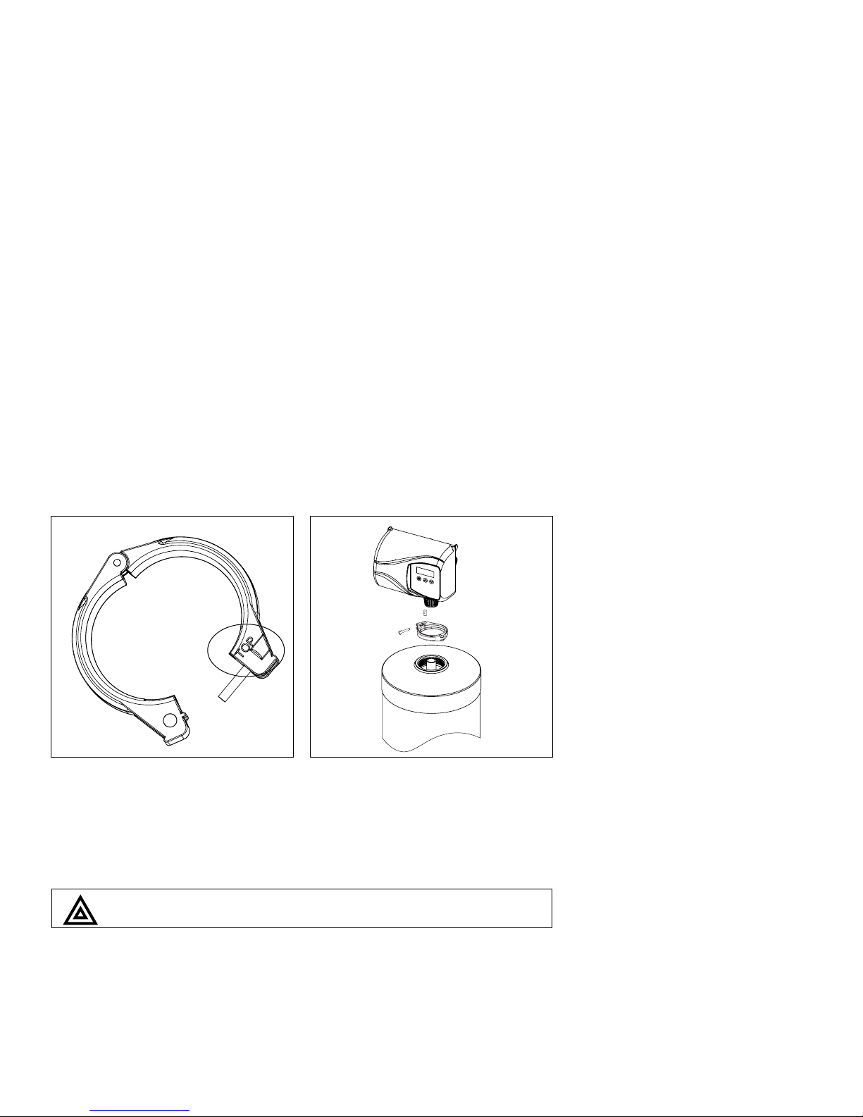
1. Clamp Ring – The clamp ring con-
nects the control valve to the tank
and provide an easy way to discon-
nect tank during control valve servic-
ing. Make sure that the clamp ring
screw is tightened.
The “Clamp Ring” should secure the valve with the top of the flange
facing up. Please note “top” on the clamp ring.
1
Installation Steps:
9
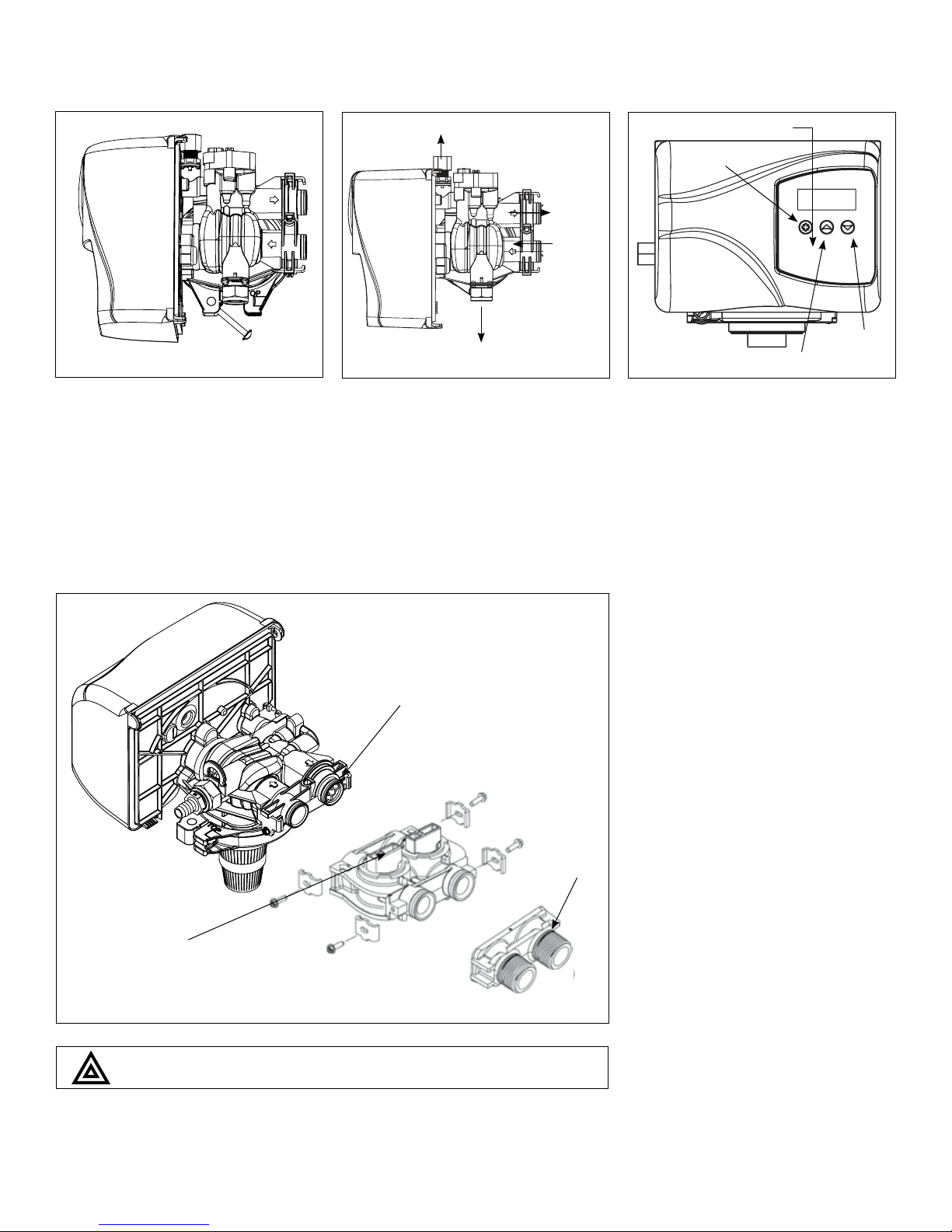
2. Familiarize yourself with the location
of the inlet, outlet and drain on the
control valve. Be very careful not to
get the controls wet.
3. Familiarize yourself with the buttons
on the timer control.
Do not use pipe thread compound as it may attack the material
in the valve body
.
Yoke
Bypass
Make sure that the flow
meter is connected to the
outlet of the valve
4
Brine Line 3/8”
Drain 1/2”
Inlet
Outlet
2
Timer Controls
DOWN
button
UP button
Extra Cycle
Button
3
4. Attach the bypass valve to the con-
trol valve (and yoke if plastic bypass
is used). Connect the inlet and outlet
of the water softener to the plumb-
ing in the house. The control valve
must not be submitted to tempera-
tures above 43°C (110°F). When
sweat fittings are used, to avoid
damaging the control valve, solder
the threaded copper adapters to
the copper pipe and then, using
Teflon tape, screw the assembly into
the bypass valve.

10
Waste connections or drain outlet shall be designed and constructed to provide for connection to the sanitary
waste system through an air-gap of 2 pipe diameters or 1 inch (22 mm) whichever is larger.
Never insert drain line directly into a drain, sewer line, or trap. Always allow an air gap between the drain line and
the wastewater to prevent the possibility of sewage being back-siphoned into the conditioner.
6. The brine line is connected to the
safety float assembly of the brine
tank. Pull the 3/8” brine line through
the hole in the back of the brine
tank. Connect the brine line to the
fitting on the side of the valve using
the nut and ferrule. Tighten snugly.
Remove the nut from the brine line
of the valve and push the other end
of the brine tube inside it. Make sure
that the brass insert is snugged inside
the brine tubing. The brine tubing
should pass through both plastic
inserts of the black nut.
7. Overflow Connection (Optional): In
the event of a malfunction, the brine
TANK OVERFLOW will direct “overflow”
to the drain instead of spilling on the
floor. This fitting should be installed at
the side of the cabinet or brine tank.
To connect the overflow line, drill
the hole on the side of the tank, 2 to
3 inches below from the top of the
brine tank. Insert overflow fitting (sold
separately part # 33006) into tank and
tighten with plastic thumb nut and
gasket as shown. Attach length of
1/2-inch (1.3-cm) I.D. tubing (not supplied) to fitting and run to drain. Do not
elevate overflow line higher than overflow fitting.
Do not tie into drain line of control unit. Overflow line must be a direct, sepa-
rate line from overflow fitting to drain, sewer or tub. Allow an air gap as per
drain line instructions.
5. Drain Line Connection: Using teflon
tape, screw the 1/2” hose barb into
the drain port in the valve. Attach
1/2” drain hose to the hose barb and
tighten securely with a hose clamp.
Run the drain line to a floor drain or
a laundry drain. Complete any
necessary plumbing.
Hose Barb
Connect 1/2”
drain hose (not supplied)
with a hose clamp here
Tube Insert
Brine
Tubing
One end of the
brine tubing come
attached to the
safety float
assembly
5
5
5
6
6
6
11
Overflow Fitting
Drain Tubing
Air Gap
Drain
Secure hose in place
8. Make sure the bypass valve is in the
service position.
9. Plug the 24-volt transformer into a
120 VAC 60 Hz outlet.
10. This valve has four positions: 1) Brine/
Rinse 2) Backwash 3) Rapid Rinse
and 4) Brine Refill. When the valve
is in the Service position must
be pressed and held for 5 seconds
before it activates. Press and hold
the pic for 5 seconds to ad-
vance the valve into the “1” Brine/
Rinse position. Press once more to
advance to the “2” position.
outlet
intlet
Circuit Board Screen
Brine Cam
Position Label
Brine
Valve
Cycle Step Abbreviation
BD Brine Draw
BW Backwash
RR Rapid Rinse
BF Brine Refill
SV Service
The valve position during regenera-
tion and servicing can be checked
in the circuit board screen as well
the position label on the cam.
7
8
9
10

12
9
11. Press the extra cycle button to advance the valve to the
“2” Backwash position. Slowly turn on the water supply
and allow the unit to backwash until the air purges out of
the tank and clears the system.
12. Press once more to advance to the “3” Rapid
Rinse position and allow water to run to drain for
2 Minutes.
Water Conditioner Flow Diagrams
Service Position Backwash Position
Brine Rinse Position Slow Rinse Position
Hard Water Soft Water
To Drain
Hard Water Soft Water
To Drain
Hard Water Soft Water
To Drain
Hard Water Soft Water
To Drain
Hard Water Soft Water
To Drain
Hard Water Soft Water
To Drain
Hard Water Soft Water
To Drain
Hard Water Soft Water
To Drain
Hard Water Soft Water
To Drain
Hard Water Soft Water
To Drain
Hard Water Soft Water
To Drain
Hard Water Soft Water
To Drain
BW
10
BD
60
IMPORTANT: THE UNIT SHOULD BE BACKWASHED FOR 15 MINUTES BEFORE SERVICE TO REMOVE ALL FINES FROM ACTIVATED CARBON BED IN THE SOFTENER

13
13. Press once more to advance to the “4” Brine refill
position. Wait until the water level reaches 6” in
the brine tank. Water can be added to the tank to
speed up the filling but the valve should be in the
Brine Refill position for a minimum of two minutes to
purge the air out of the injector set.
Rapid Rinse Position Brine Refill Position
Hard Water Soft Water
To Drain
Hard Water Soft Water
To Drain
Hard Water Soft Water
To Drain
Hard Water Soft Water
To Drain
Hard Water Soft Water
To Drain
Hard Water Soft Water
To Drain
RR
10
BF
12
14. Press to advance the valve from the Brine Fill position through service to the “1” position Brine/
Rinse position. Verify that water is being drawn from the tank. If not, repeat step 9.
15. Press button to advance the valve to the “2” Backwash position.
16. Press to advance the valve to the “3” Rapid Rinse position.
17. Press to advance the valve to the “4” Brine Fill position until there is 6” of water in the brine tank.
Press to advance the valve back into the service position indicated by the in upper left corner
of the display.
14
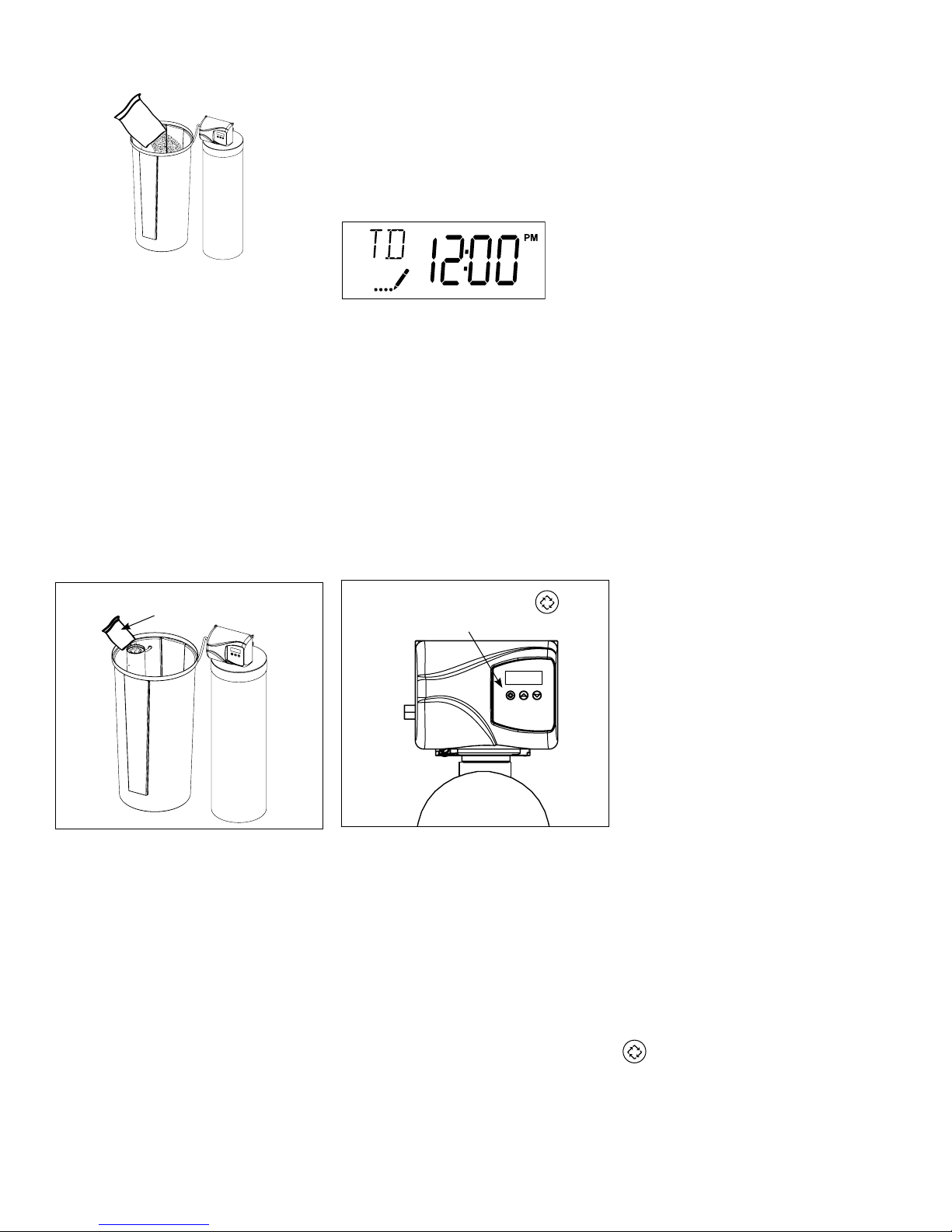
19. Set time of the day in the control
valve and program the user section of
the control. Refer to control valve pro-
gramming section in this manual.
Sanitization can also achieved by the application of chlorine in the regeneration cycle of the conditioner. A liquid solution
of 5.25% sodium hypochlorite (commonly referred to as household bleach) is recommended as a suitable disinfectant.
Use only unscented products. For every cubic foot of resin in the softener, pour approximately two (2) tablespoons of so-
dium hypochlorite into the brine well tube. The brine tank refill step of regeneration should add the correct amount of water
to the brine tank. If not, the water can be added manually now. Press and hold the to begin a manual regeneration.
Allow softener to complete the Brine/Rinse cycle, then let the manual regeneration continue until the brine tank is refilled
again with the correct amount of water.
NOTE: ALL STATE AND LOCAL GOVERNMENT CODES GOVERNING INSTALLATION OF THESE DEVICES MUST BE OBSERVED.
18. Put 40 kgs of crystal water softener
salt in the brine tank. The unit will
automatically fill the water to the
correct level when it regenerates.
Optional Sanitization Procedure: We recommend that all new water conditioners be disinfected as
part of the startup.
Water Softener Sanitization
Press and Hold
to manually regenerate
Sanitization Solution
1a. Pour entire packet of Sani-System
Liquid Concentrate – Part # 50032
(24 packets) into the brine well. If
no brine well is present, pour entire
packet into bottom of brine tank
when salt is nearly empty.
1b. Manually regenerate the softener
according to the manufacturer’s
specifications.
1a 1b
15
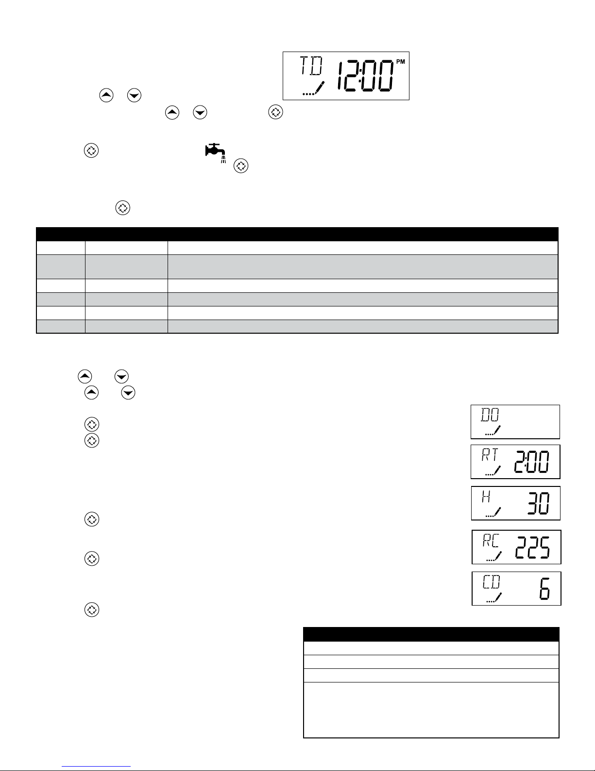
User Programming Mode Steps
Note: Use and Down button to adjust values for parameters
1. Press the and buttons for five seconds while in service, and the time of day is NOT set to 12:01 PM.
2. Use this display to adjust the Day Override. Adjust this to OFF parameter for softeners.
3. Press the button. Use this display to adjust the Regeneration Time.
4. Press the button. Use this display to adjust the Feed Water Hardness in grains per gallon (gpg).
Hardness Compensation
1 mg/l of iron = 4 gpg
1 mg/l of manganese = 8 gpg
Maximum iron is not to exceed 1.5 mg/l total iron
Recommend the addition of a Res-up feeder when the total iron exceeds 0.5 mg/l
5. Press the button. Use this display to adjust the Fixed Reserve Capacity. This option setting is
identified by “RC” in the upper left-hand corner of the screen. 75 gallons X # of people in the
house = RC
6. Press the button. Use this display to set the Current Day of the Week. This option setting is
identified by “CD” in the upper left hand corner of the screen. This option is only available after the
Day of the Week control is set to ‘ON’ in the Master Programming. Refer to the valve manual for
details.
7. Press the button to end User Programming Mode.
Programming Instructions
Set Time of Day
Press and hold or buttons until display reads TD
Adjust the displayed time with or buttons. Press to resume normal operation
Queuing a Regeneration
1. Press the button. The service icon will flash to indicate that a regeneration is queued.
2. To cancel a queued regeneration, press the button.
Regenerating Immediately
Press and hold the button for five seconds.
User Programming Mode Options
Abbreviation Parameter Description
DO Day Override The timer’s day override setting
THIS IS AN OPTION ONLY. PLEASE DO NOT ADJUST BEFORE CONSULTING AN AUTHORIZED DEALER.
RT Regeneration Time The time of day that the system will regenerate (meter delayed, timeclock, and day-of-week systems)
H Feed Water Hardness The hardness of the inlet water - used to calculate system capacity for metered systems
RC Reserve Capacity The fixed reserve capacity
CD Current Day The current day of week
OFF
OFF
OFF
OFF
OFF
In the second level mode, the control valve has been pro-
grammed as per the following main parameters related to
regeneration. For more information on master programming
manual, read control valve manual part # 54802
The valve has been pre-programmed with factory settings
as shown in the following chart:
Regeneration Cycle Step Programming
1. Brine Rinse 60 minutes
2. Backwash 10 minutes
3. Rapid Rinse 10 minutes
4. Brine Refill
12 minutes
16 minutes
10 minutes
16 minutes
12 minutes
MXC75
MXC10
MXC125
MXC20
MXC30

16
5. Press . Use this display
to view the Volume
Used since the last
regeneration cycle. This
option setting is identified
by “VU” in the upper
left hand corner of the
screen.
6. Press . Use this display
to view the Reserve
Capacity. This option
setting is identified by
“RC” in the upper left
hand corner of the
screen.
7. Press . Use this display
to view the Software
Version. This option setting
is identified by “SV” in the
upper left hand corner of
the screen.
8. Press to end Diagnostic Programming Mode.
Diagnostic Programming Mode
Diagnostic Programming Mode Steps
1. Press the and buttons for five seconds while in
service.
2. Use this display to view
the current Flow Rate.
This option setting is
identified by “FR” in the
upper left hand corner
of the screen.
3. Press . Use this display
to view the Peak Flow
Rate since the last
regeneration cycle. This
option setting is identified
by “PF” in the upper
left hand corner of the
screen.
4. Press . Use this display
to view the Hours in
Service since the last
regeneration cycle. This
option setting is identified
by “HR” in the upper
left hand corner of the
screen.
Diagnostic Programming Mode Options
Abbreviation Parameter Description
FR Flow Rate Displays the current outlet flow rate
PF Peak Flow Rate Displays the highest flow rate measured since the last regeneration
HR Hours in Service Displays the total hours that the unit has been in service
VU Volume Used Displays the total volume of water treated by the unit
RC Reserve Capacity Displays the system’s reserve capacity calculated from the system
capacity, feed water hardness, and safety factor
SV Software Version Displays the software version installed on the controller
NOTES:
Some items may not be shown depending on timer configuration.
The timer will exit Diagnostic Mode after 60 seconds if no buttons are pressed.
Press the Extra Cycle button to exit Diagnostic Mode at any time.

17
Controller Behavior
Control Operation During Programming
The control will only enter the Program Mode with the valve in Service. While in the Program Mode, the control will
continue to operate normally, monitoring water usage and keeping all displays up to date. Control programming is stored
in memory permanently, eliminating the need for battery back-up power.
Meter Immediate Control
A meter immediate control measures water usage and regenerates the system as soon as the calculated system capacity
is depleted. The control calculates the system capacity by dividing the unit capacity (typically expressed in grains/unit
volume) by the feedwater hardness and subtracting the reserve. Meter Immediate systems generally do not use a reserve
volume. However, in twin tank systems with soft-water regeneration, the reserve capacity should be set to the volume
of water used during regeneration to prevent hard water break-through. A Meter Immediate control will also start a
regeneration cycle at the programmed regeneration time if a number of days equal to the regeneration day override
pass before water usage depletes the calculated system capacity.
Meter Delayed Control
A Meter Delayed Control measures water usage and regenerates the system at the programmed regeneration time after
the calculated system capacity is depleted. As with Meter Immediate systems, the control calculates the system capacity
by dividing the unit capacity by the feedwater hardness and subtracting the reserve. The reserve should be set to insure
that the system delivers treated water between the time the system capacity is depleted and the actual regeneration
time. A Meter Delayed control will also start a regeneration cycle at the programmed regeneration time if a number of
days equal to the regeneration day override pass before water usage depletes the calculated system capacity.
Time Clock Delayed Control
A Time Clock Delayed Control regenerates the system on a timed interval. The control will initiate a regeneration cycle at
the programmed regeneration time when the number of days since the last regeneration equals the regeneration day
override value.
Day of the Week Control
This control regenerates the system on a weekly schedule. The schedule is defined in Master Programming by setting
each day to either “off” or “on.” The control will initiates a regeneration cycle on days that have been set to “on” at the
specified regeneration time.
Control Operation During a Power Failure
The SXT includes integral power backup. In the event of power failure, the control shifts into a power-saving mode. The
control stops monitoring water usage, and the display and motor shut down, but it continues to keep track of the time and
day for a minimum of 48 hours.
The system configuration settings are stored in a non-volatile memory and are stored indefinitely with or without line power.
The Time of Day flashes when there has been a power failure. Press any button to stop the Time of Day from flashing.
If power fails while the unit is in regeneration, the control will save the current valve position before it shuts down. When
power is restored, the control will resume the regeneration cycle from the point where power failed. Note that if power fails
during a regeneration cycle, the valve will remain in it’s current position until power is restored. The valve system should
include all required safety components to prevent overflows resulting from a power failure during regeneration.
The control will not start a new regeneration cycle without line power. If the valve misses a scheduled regeneration due to
a power failure, it will queue a regeneration. Once power is restored, the control will initiate a regeneration cycle the next
time that the Time of Day equals the programmed regeneration time. Typically, this means that the valve will regenerate
one day after it was originally scheduled. If the treated water output is important and power interruptions are expected,
the system should be setup with a sufficient reserve capacity to compensate for regeneration delays.
18
During Regeneration
Automatic Bypass
The regeneration cycle lasts approximately 2 hours, after which soft water service will be restored. During regeneration, hard
water is automatically bypassed for use in the household. Hot water should be used as little as possible during this time to
prevent hard water from filling the water heater.
IMPORTANT: This is why the automatic regeneration is set for sometime during the night and manual regenerations should be
performed when little or no water will be used in the household.
New Sounds
You may notice new sounds as your water softener operates. The regeneration cycle lasts approximately 2-1/2 hours. During
this time, you may hear water running intermittently to the drain.
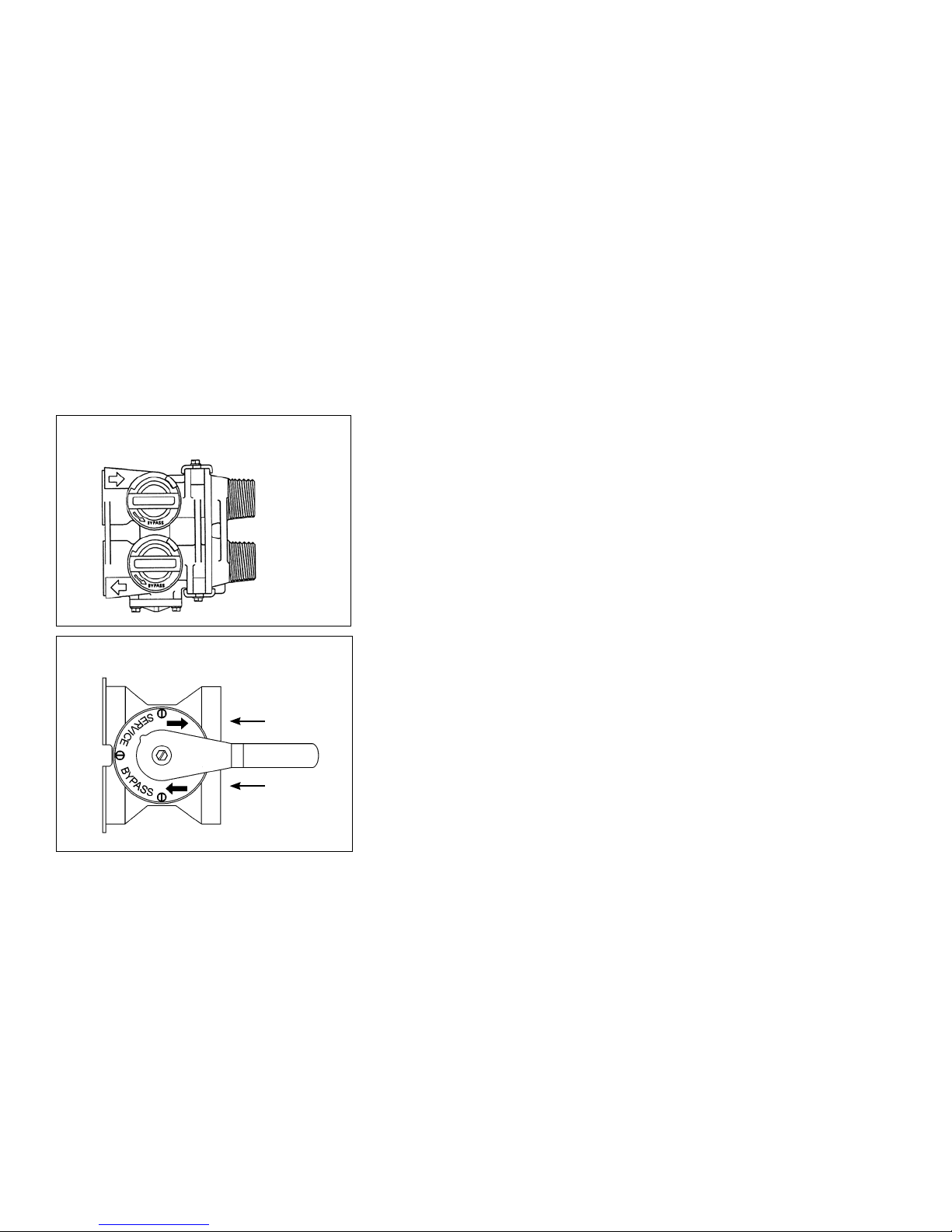
Water Bypass
Manual Bypass (Figure 5A)
In case of an emergency such as an overflowing brine tank, you can isolate
your water softener from the water supply using the bypass valve located
at the back of the control. In normal operation the bypass is open with the
ON/OFF knobs in line with the INLET and OUTLET pipes. To isolate the softener,
simply rotate the knobs clockwise (as indicated by the word BYPASS and ar-
row) until they lock. You can use your water related fixtures and appliances
as the water supply is bypassing the softener. However, the water you use will
be hard. To resume soft water service, open the bypass valve by rotating the
knobs counter-clockwise.
Stainless Steel Bypass (Figure 5B)
In normal operation the bypass lever is aligned with the inlet/outlet with the
pointer on SERVICE. To isolate the softener or filter, rotate lever counter clock-
wise until it stops and pointer indicates unit is in bypass.
You can use your water related fixtures and appliances as the water supply is
bypassing the softener and filter. However, the water you use will be hard or
untreated. To resume treated water service, open the bypass valve by revers-
ing the rotation of the lever.
Outlet
Inlet
Outlet
Inlet
Figure 5B
Figure 5A

19
Checking the Salt Level
Check the salt level monthly. Remove the lid from the cabinet or brine tank, make sure salt level is always above
the brine level
NOTE: You should not be able to see water
Adding Salt
Use only clean salt labeled for water conditioner use, such as crystal, pellet, nugget, button or solar.
The use of rock salt is discouraged because it contains insoluble silt and sand which build up in the brine tank and can
cause problems with the system’s operation.
Add the salt directly to the tank, filling no higher than the top of the brine well.
Bridging
Humidity or the wrong type of salt may create a cavity between the water and the salt.
This action, known as “bridging”, prevents the brine solution from being made, leading to
your water supply being hard.
If you suspect salt bridging, carefully pound on the outside of the plastic brine tank or pour
some warm water over the salt to break up the bridge. This should always be followed up
by allowing the unit to use up any remaining salt and then thoroughly cleaning out the
brine tank. Allow four hours to produce a brine solution, then manually regenerate the
softener.
CAUTION! Liquid brine will irritate eyes, skin and open wounds -
gently wash exposed area with fresh water. Keep children away from
your water conditioner.
Care of Your Softener
To retain the attractive appearance of your new water softener, clean occasionally with a mild soap solution. Do not use
abrasive cleaners, ammonia or solvents. Never subject your softener to freezing or to temperatures above 43°C (110°F).
Servicing Components.
• Theinjectorassemblyshouldbecleanedorreplacedeveryyeardependingontheinletwaterqualityandwaterusage.
• Thesealsandspacercartridgeshouldbeinspected/cleanedorreplacedeveryyeardependingontheinletwater
quality and water usage.
Please refer to the servicing section of this manual for step by step procedure.
Not following the above will void all warranty on the control valve.
Resin Cleaner
An approved resin cleaner MUST be used on a regular basis if your water supply contains iron. The amount of resin cleaner
and frequency of use is determined by the quantity of iron in your water. (Consult your local representative or follow the
directions on the resin cleaner package).
Maintenance Instructions
Other manuals for 6200 SXT
1
Table of contents
Other WaterGroup Water Filtration System manuals


