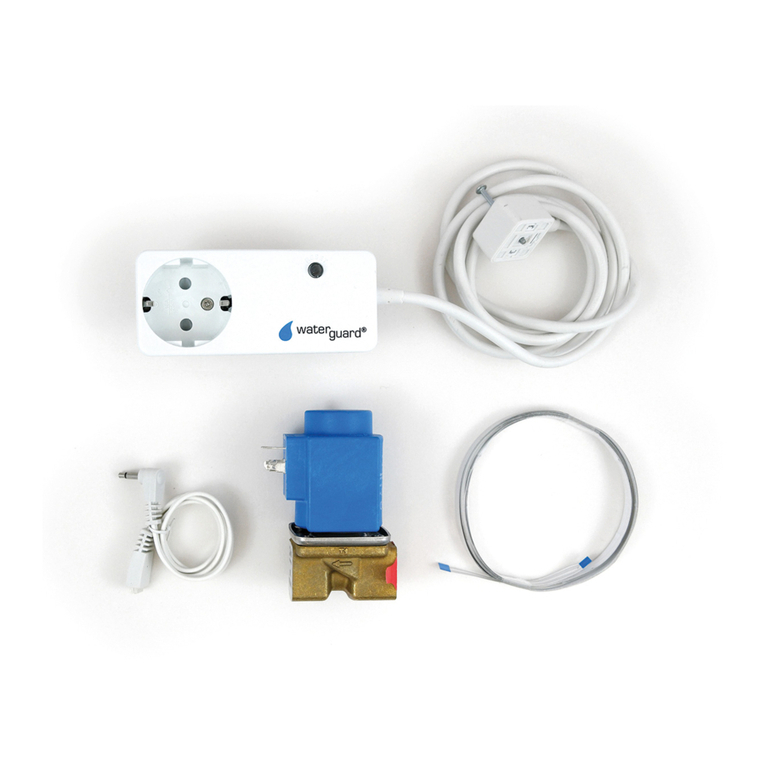
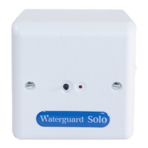
WATERGUARD Solo User manual

Dedicated technical helpline: 01226 397987 © 2022 Waterguard Services Limited, All Rights Reserved
Waterguard Solo Installation Guide
IMPORTANT! CURRENT IEE REGULATIONS: THE SERIES 7 SHOULD BE INSTALLED BY A QUALIFIED
ELECTRICIAN, IN ACCORDANCE WITH THE RECOMMENDATIONS LAID DOWN BY THE HVCA AND SOUND
ENGINEERING PRACTICE. A COMPETENT PLUMBER MUST CARRY OUT THE ASSEMBLY AND INSTALLATION
OF ANY WATER METERS AND VALVES. ANY DAMAGES INCURRED DUE TO IMPROPER INSTALLATION ARE
NOT COVERED UNDER WARRANTY.
IMPORTANT: PLEASE READ THIS GUIDE CAREFULLY AND IN FULL BEFORE INSTALLING.
KEEP CLEAN: DO NOT LET DEBRIS ENTER THE WATER METER(S) OR VALVE(S).
STORAGE: KEEP IN A DRY PLACE PRIOR TO INSTALLATION TO AVOID POSSIBLE DAMAGE TO INTERNAL
COMPONENTS.
ATTENTION: IT IS IMPORTANT TO STRICTLY FOLLOW THESE
INSTRUCTIONS IN FULL. THE 3V LITHIUM BATTERY MUST ONLY BE
CONNECTED AFTER MAINS POWER. FAILURE TO DO THIS WILL RESULT IN
SYSTEM FAILURE.
NEW BUILD INSTALLATION: DO NOT INSTALL VALVE ASSEMBLY PRIOR TO
FLUSHING THE SYSTEM AS THIS WILL CAUSE DEBRIS TO BECOME LODGED
IN THE FLOW SENOR AND WILL REQUIRE REPLACEMENT.

Dedicated technical helpline: 01226 397987 © 2022 Waterguard Services Limited, All Rights Reserved
Waterguard Solo Installation Guide
INFORMATION
WHAT YOU WIIL NEED
ITEMS:
•2 Core Flex - PVC 2 Core Flat Flexible Cable (2192Y) min 0.75mm2 if connecting to intruder
alarm or BMS
•3 core mains cable
•PTFE tape
•Valve assembly connectors (standard kit only)
•1 x single pattress boxes (standard kit only)
No responsibility can be accepted by the manufacturer or distributors of this equipment for any
misinterpretation of an instruction or guidance note or for the compliance of the system.
This system protects properties by monitoring water usage from the incoming water mains using
a flow sensor that allows continuous water flow for a limited time before the controller suspects a
leak and automatically shuts off the water with a solenoid valve.
The Waterguard Solo has one level of guard (maximum time of continuous flow) which is usually
set by the installer, landlord or concierge with the controls often located in riser cupboards or
basements.
Waterguard Solo
Size
85 x 85 x 42mm
Backup Battery
Yes: 3V Lithium, provides 1 month
minimum backup
Power
240V
Alarm Output
Switching voltage: 48V max 0.1V
min
Cable
Requirements
2 Core Flex - PVC 2 Core Flat
Flexible Cable (2192Y) min
0.75mm2 if connecting to BMS. 3
core mains cable. Not supplied.
Valve Common Flow
Solenoid Valve: V & C
Flow Sensor: F & C
See below for technical data.
Waterguard Flow Sensor –WRAS Cert No. 2011700
Material
Mechanical Specifications
Housing Material
Noryl
Shock
50g for 11mS dur
Shuttle Material
Noryl
Vibration
35g up to 500Hz
Contact Material
Ruthenium
Maximum Pressure
10 bar @ 20
Operating
Temperature
-30 to 85 degrees C
IP
IP65
Medium
Water
Horizontal flow rate l/min
2.24
Housing Colour ¾”
Blue
Vertical (flow up) flow rate l/min
2.50
Housing Colour 1 ¼”
Black
Vertical (flow down) flow rate
l/min
1.79

Dedicated technical helpline: 01226 397987 © 2022 Waterguard Services Limited, All Rights Reserved
Waterguard Solo Installation Guide
Switching
Technical Drawings
Switch Action (Reed
Switch)
SPST
Max Switch Voltage VDC
200
Max Switch Voltage VAC
250
Max Switching Current
Amps
1
Max Switching Load Watt
40
Reed Switch Reliability
UL File E153493
Operate Mode
N/O, close with flow
Contact Form
A
Cable & Mounting
Cable Length
1 x 1.0M double
insulated
Connection Type
Stripped cables
Cable Type
0.5MM2 BS6500
PVC
Cable Colour
Grey outer
blue/brown in
Fitting
¾” or 1 ¼” BSP with
male and female
threads
Fitment
In line
Mounting
Vertical, flow
downwards
Solenoid Valve –WRAS Cert No. 1901033
Classification
Hydraulic Connections
Type
Single
Inlet
BSP Female Thread
Geometry
180 C
Outlet
BSP Female Thread
Working Specifications
Physical Specifications
Working Pressure
0.5 / 10 bar
Valve Body
Polyamide 30% fibre glass
Room Temperature
0 / 60 C
Diaphragm and Gaskets
NBR (buna)
Fluid Temperature
60 C
Core
Stainless Steel
Duty Cycle
ED 100%
Spring
Stainless Steel
Flow Direction
Unidirectional
Assembly
With screws for inspection
Nominal Diameter
DN ½” – 1 ¼”
Coil
Watertight –C.E.I IP 55
Control
NC, NO, Latching
Cable Length
Aprox 600mm
In all positions, manual override by solenoid coils rotation.
Electrical Connections
Electric Connect 1
Male Faston 6.3 x 0.8 mm –IP X0
Electric Connect 2
Unipolar Cables max 300 mm –IP 55
Electric Connect 3
Bipolar Cables max 5000 mm –IP 55

Dedicated technical helpline: 01226 397987 © 2022 Waterguard Services Limited, All Rights Reserved
Waterguard Solo Installation Guide
Ensure to fit the Solo indoors in a dry area with easy access. This controller is not suitable for
external installation. It is recommended mains power is provided from an adjacent 3 amp un-
switched fused spur. Do not connect mains power until all electrical connections are complete. Do
not connect backup battery before mains power.
A competent plumber must carry out the assembly and installation of the Waterguard residential
valve assembly. Install in a suitable location close to where the water supply enters the property.
Direction of flow is essential for correct operation. Ensure to shut off the water supply and drain
before cutting the pipe, approximately 9-11”. After plumbing the valve assembly turn on the water
supply and check for leaks. Re-lag the pipework where required. Do not over tighten or overuse
PTFE tape.
1. Wire the latching solenoid
valve and flow sensor to the
Solo controller:
•Red to V
•Black and Brown to C
•Blue to F
Valve and flow sensor cable
can be extended using 2 core
1.0mm screened cable.
2. Where applicable, use 2 core
flex cable to connect the BMS
to the ALARM OUT terminal.
3. Connect power, mains supply
cable to fused spur.
4. Connect 3V battery. DO NOT CONNECT THIS BEFORE POWER.
Waterguard residential valve assembly.

Dedicated technical helpline: 01226 397987 © 2022 Waterguard Services Limited, All Rights Reserved
Waterguard Solo Installation Guide
Power and unit operation are indicated by a solid red light on the controls. On initial power up the
LED will flash once per second for approximately 2 minutes. Some software versions will go into
an alarm state during this time, the valve will close, and the controls will flash red intermittently, to
open the valve press the controls push once.
Check the LED on the Solo switches on and is a solid red light when mains power is applied. Run
the water in the property (the Solo will perform 2 brief flashes every 2 seconds indicating that
water is flowing).
Check flow sensor for debris if this occurs without water running.
Whilst the water is running press the button on the controls and release, after 10 seconds the
controller will close the valve and water will stop running. The controller will flicker on and off
every second indicating that the valve is closed, press the button again to open the valve and
reinstate the water. If no water runs on test check valve polarities, if extending valve assembly
cable ensure wiring is in correct terminal.
All Waterguard Solo controls are pre-set to allow a maximum of 20 minutes continuous water flow
unless an alternative time is requested at time of purchase. To change this default setting, follow
the instructions below:
Press and hold the Solo button for approximately 25 seconds, the Solo is now in set up mode.
Ensure you do not release the button after the initial 25 seconds and the Solo will flash as below in
5 second intervals.
•1 flash = 10 minutes
•2 flashes = 20 minutes
•3 flashes = 30 minutes
Release the Solo button once the LED indicator has shown the required number of flashes for the
time limited required. Set up complete.
To check the correct settings have been entered press and hold the button for 6 seconds and
release, the LED will flash to indicate the current time limit:
•1 flash = 10 minutes
•2 flashes = 20 minutes
•3 flashes = 30 minutes
A generic commissioning and testing checklist is available upon request.
22 Oakwell Business Centre T: 01226 244200
To find your solution visit
All information provided, including installation is held to be reliable. Clients should however independently evaluate the suitability of each system to their individual application. Due to
continual development specifications are subject to regular change without notice. Waterguard Services Limited make no claims, promises, or guarantees to the accuracy or
completeness of, and expressly disclaims liability for any errors and omissions in, such materials. No warranty of any kind, implied, expressed, or statutory, including but not limited to
the warranties included within Waterguard Services Limited Standard Terms and Conditions of Sale is given with respect to the content of these marketing materials. In no case will
Waterguard Services Limited be liable for any incidental, indirect or consequential damages arising from the sale, resale, use or misuse of the product. ©2022 Waterguard Services
Limited, All Rights Reserved.
Other manuals for Solo
5
Other WATERGUARD Plumbing Product manuals
Popular Plumbing Product manuals by other brands

Mirabelle
Mirabelle CALVERTON MIRXCCA100CP installation instructions

Toto
Toto NEOREST installation guide

Sterling Plumbing
Sterling Plumbing Shower Receptor and Wall Surround 72110100 Specification sheet

Gessi
Gessi 39821 Maintenance manual

Geberit
Geberit 11 5.083.SI.1 installation manual

Grohe
Grohe Grohtherm 1000 34065DC2 manual