Waterous Aquis Foam Manager User manual

Read through the safety information and operating
instructions carefully before using your Waterous
Foam Manager.
Table of Contents
Safety Information 2..............................................
Introduction 3...................................................
System Overview 3.............................................
System Components 4..........................................
Operation 4......................................................
Water Only Operation 4..........................................
AquistFoam Pump Operation 5.................................
Foam Operation 6..............................................
Shut Down Procedures 6.........................................
Foam System Flush 6...........................................
Service and Maintenance 6.......................................
Maintenance Schedule 6........................................
Location of Maintenance Items 6..................................
Advantus Foam Pump 6.......................................
Oil Fill and Drain 6.........................................
In−line Foam Concentrate Strainer 6..........................
Calibration 7.....................................................
Aquis Foam Pump 7............................................
Troubleshooting Guide 8.........................................
Foam Manager with Advantus
Waterous Company 125 Hardman Avenue South, South St. Paul, Minnesota 55075 USA (651) 450−5000
Instructions subject to change without notice.
Visit us at www.waterousco.com
IL3436
Section
2414
Form No.
F−1031
Issue Date
03/11/10
Rev. Date
05/13/13
Foam ManagertSystem
with Aquist
Operation and Maintenance

F−1031, Section 2414 Page 2 of 8
Safety Information
Read through the safety information and operating instructions before using your Waterous Foam
Manager.
WARNING
!
Death or serious personal injury might occur if proper
operating procedures are not followed. The pump op-
erator, as well as individuals connecting supply or dis-
charge hoses to the apparatus must be familiar with
these pump operating instructions as well as other
operating instructions and manuals for the apparatus,
water hydraulics and component limitation.
WARNING
!
Pressure Hazard. May result in personal injury.
Prior to connection or removal of hoses, caps or other
closures with pump intake or pump discharge connec-
tions, relieve pressure by opening drains or bleeder
valves. Bleeder valves should also be used while filling
a hose connected to an intake with water.
WARNING
!
Scalding Water Hazard. May result in serious burns.
When operating the pump, be sure to open at least
one discharge valve slightly to prevent the pump from
overheating. If the pump runs for a few minutes com-
pletely closed, it may heat the water enough to scald
someone when the valve is opened. Overheating can
damage the packing, seals and other pump parts. If
the apparatus builder has installed a by−pass system
or other provision designed to prevent overheating,
opening a discharge valve may be unnecessary.
WARNING
!
Hose Pressure Hazard.
May cause serious personal injury.
Use only fire hose that is rated at 200 PSI or higher
working pressure.

F−1031, Section 2414 Page 3 of 8
Introduction
System Overview
NOTE: Read and understand the operating instruc
tions for the Foam Manager System prior to operating.
(Refer to Figure 1 for system components.)
The Foam ManagertSystem consists of an Aquist
Foam Proportioning System mounted on a Waterous CM
or CS fire pump.
Aquist2.5 Foam Proportioning System
The Aquis foam proportioner from Waterous delivers a
level of performance and reliability typically reserved for
more expensive Class A foam proportioners. Aquis 2.5
features a non-corroding brass body pump as well as
sensors that measure water temperature and water flow to
create the ideal water to concentrate ratio for superior
foam.
Foam Pump
The 12 or 24-volt, electric motor driven, positive displace
ment triplex plunger foam pump is equipped with an alu
minum crankcase, ball bearings, forged brass pump body
and manifold, solid ceramic plungers, stainless steel
check valves and piston guides, Buna packing and preset
thermal and pressure relief valves.
The foam pump is rated at 2.5 GPM @ 150 psi (9.46 l/min
@ 10 bar) with operating pressures up to 450 psi (32 bar).
Maximum electrical load of 40 amps @ 12 VDC and 21
amps @ 24 VDC.
A pump motor electronic driver, located inside the control
ler housing, receives signals from the microcontroller and
powers the 1/2 hp (.4 kW) electric motor in a variable
speed duty cycle to ensure that the correct amount of
foam concentrate set by the pump operator is injected into
the water stream.

F−1031, Section 2414 Page 4 of 8
System Components
Table 1. System Components
Ref. No. Description
1AquistFoam Pump (Proportioner)
2Foam Pump Inject Valve
3In−line Foam Concentrate Strainer
Ref. No. Description
4AquistFoam Pump OIT (Control Panel)
5AquistOperation Instruction Panel Plate
6OIT Cable
Figure 1. System Components
1
2
4
3
To Foam Tank
5
36
Items Shipped Loose
with Aquis Foam Pump
IL3436
Optional Items from Waterous
Description
Foam Tank Level Switch
Aquis Rating Panel Plate
Aquis System Schematic Panel Plate
OIT (Control Panel) Extension Cable
Operation
A pumper equipped with a Foam Managertfoam unit can
be operated in water only and/or foam modes. It is pos
sible to pump water from one discharge and foam solution
from another discharge.
Water Only Operations
All unit operations begin with pumping water. See the fol
lowing instruction for details on how to operate and pump
water from your Waterous fire pump:
·F-1031, Section 2114, Operation and Maintenance
Instructions for Waterous CMU Series Centrifugal Fire
Pumps
or
·F−1031, Section 2115, Operation and Maintenance
Instructions for Waterous CS and CSU Series Centrif-
ugal Fire Pumps
CAUTION
Overheating hazard.
May cause damage to the pump.
Running the unit without adequate water flow or an
overheated water supply can cause damage to the
pump.

F−1031, Section 2414 Page 5 of 8
AquistFoam Pump Operation
Upon power up, the software revision number will be dis
played. The unit will then display the flow rate.
The software will perform a linear interpolation to determ
ine values to use for flow rates that are in between flow
rates entered in the data array.
Figure 2. Operator Interface Terminal
IL3437
During normal operation, the OIT (Operation Interface Terminal) will display flow rate, percent mix, total water or total
product.
SELECT Selects data to display. The default is to display flow rate. Pressing the SELECT button will
scroll through the list, then wrap back around to the top of the list. The associated LED will
light to indicate what data is being displayed.
Flow Rate
Mix Percentage
Total Water
Total Product
Holding the SELECT button for more than two (2) seconds will lock the display to the current
position. Pressing the SELECT button again will unlock.
UP ARROW When the Mix Percentage is displayed, the current mix setpoint will be displayed. Sub
sequent presses of the UP ARROW button will increase the Mix Setpoint by 0.1%. After a ten
(10) second timeout, the display will return to the Flow Rate display.
DOWN ARROW When the Mix Percentage is displayed, the current mix setpoint will be displayed. Sub
sequent presses of the DOWN ARROW button will decrease the Mix Setpoint by 0.1%. After
a ten (10) second timeout, the display will return to the Flow Rate display.
Pressing both UP and DOWN simultaneously when the Total Water is displayed resets the
Total Water accumulator to Zero.
Pressing both UP and DOWN simultaneously when the Total Product is displayed resets the
Total Product accumulator to Zero.
Pressing both UP and DOWN simultaneously for two (2) seconds, when the Flow Rate is
displayed enters the MANUAL mode of operation. See Manual Mode operation below.
Pressing both UP and DOWN simultaneously while in Mix % will go to the preset default %.
FOAM Pressing the FOAM button will alternately start and stop the foam operation. When the con
troller is running, the FOAM LED will be lit. The FOAM LED will blink when the motor control
output is active.
MANUAL MODE If the display is showing the flow rate and the two ARROW keys are pressed simultaneously,
held for two (2) seconds, the % MIX LED will light and the display will show a default value of
2.0. Use the UP and DOWN arrow keys to increase or decrease this value in steps of 0.5.
NOTE: Pump output is based on a theoretical ratio of foam to water at 50 GPM.
Pressing both ARROW keys again exits the MANUAL mode and stops the pump.
While in manual mode, you can pause the motor by pressing the RED FOAM button (once).
You can increase or decrease the foam percentage at this time. Resume foam flow by press
ing the RED button once.
Pressing both ARROW keys again exits the MANUAL mode and stops the pump.
NOTE: Motor/Pump Assembly will operate in MANUAL mode whether or not there is a
water flow. If the INJECT/BYPASS valve is in the INJECT position, foam concentrate
will be injected into the system, which will waste foam concentrate.
AUTO RUN The system is equipped with an AUTO RUN feature. If the voltage (+12 or 24 VDC) is ap
plied to position 1 on the terminal strip, it will have the same effect as pressing the Red
FOAM button. This will start the Foam system. The system will not inject foam until water is
flowing.

F−1031, Section 2414 Page 6 of 8
Foam Operation
After the pump is operating, turn on the foam pump to in
ject foam concentrate into the water stream.
Refer to Aquis Foam Pump Operation Instructions on
Page 4.
Foam System Flush
1. Turn off Foam Pump. 2. Flow clear water through discharges that were used
until clear water is flowing from the nozzle.
Service and Maintenance
Maintenance Schedule
Table 2. Maintenance Schedule - Foam Pump (See Figure 3)
Check Oil
Level and
for Oil
Leaks
Foam Pump Oil Check and
Clean Foam
Concentrate
In−line
Strainer
Flushing System
Change
Foam
Pump
Model
Level from
Top of Oil
Fill Port
Capacity
Required for Oil
Change
Use Oil
Daily or
After Each
Use
Annually Aquis 2.5 1/4 inch
(6 mm)
.90 quarts
(Total capacity is
1.0 quart)
Synthetic
10W−30
(Mobil 1
recommended)
Monthly
Depending on the corrosiveness of the
foam concentrate to be used, flushing of
the foam injection circuit may be
necessary. Most Class A foam concen-
trates are less corrosive and may not
require flushing.
Location of Maintenance Items
The following figures show the location of the Aquis™ Foam Pump oil fill and drain.
Figure 3. AquistFoam Pump Oil Fill and Drain, In-line Foam Concentrate Strainer
Oil Fill
Oil Drain
(Located Under
Motor)
In−line Foam Concentrate Strainer
To Foam Tank
IL3438

F−1031, Section 2414 Page 7 of 8
Calibration
AquistFoam Pump
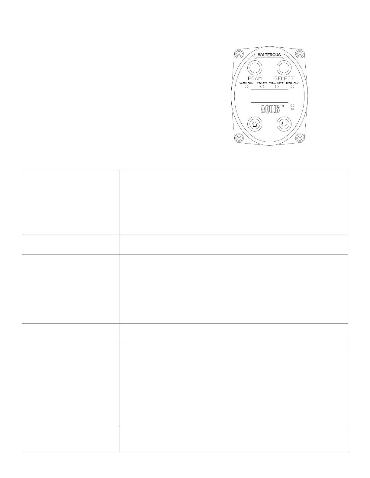
The Aquistsystem is able to be field calibrated using the con
trol function buttons on the operating interface terminal (OIT),
see Figure 8.
Only units of measure, water flow and the foam percent
age default can be field set.
A. Entering Calibration Mode
1. Entering calibration is accomplished by using the con
trol unit functions buttons.
2. To enter this function, press and hold the SELECT but
ton for minimum of five (5) seconds. The OIT will dis
play “5 SEC”.
3. Continue to hold the SELECT button.
4. While the SELECT button is depressed, push the UP
and DOWN arrow buttons at the same time. The display
will show CAL for two (2) seconds and then display F1.
5. Use the UP button to advance to the next parameter
(F2, F3, F4).
6. Use the DOWN button to back up to a previous para
meter (F2, F1).
7. To edit a parameter, press the SELECT button at the
associated Fn prompt.
B. F1 - Default Mix Percentage
1. At the F1 prompt, press the SELECT button.
2. Use the UP and DOWN arrow buttons to select the de
fault FOAM %. The only foam % selections will be .1%,
.2%, .3%, .4%, .5%, .6%, .7%, .8%, .9%, 1.0%, 3.0%
and 6.0%.
3. When finished, press the SELECT button to save the
displayed value.
C. F2 - Units of Measurement
The units of measurement must be selected prior to any
calibration functions. Units of measurement are U.S. Gal
lons, Imperial Gallons and Liters.
1. Push the SELECT button at the F2 prompt. The display
will show the current setting.
2. Use the UP and DOWN arrow buttons to select one of
the following measurement units:
·GAL will select U.S. Gallons
·IPL will select Imperial Gallons
·LTR will select Metric Liters
3. Pushing the SELECT button will save the displayed
selection. This will allow for calibration of the water flow
in the units of measurement selected.
D. F3 - Flow Rate Calibration
1. Press the SELECT button at the F3 prompt. The
current measured flow rate will be displayed. Es
tablish a flow using an accurate flow measuring
device.
2. Once this is established, press the UP or DOWN but
ton to advance to the calibration step. If the displayed
flow rate is correct, press the SELECT button to return
back to the F3 prompt. If there is insufficient flow, the
display will show LoFL for two (2) seconds, then return
back to the F3 prompt.
3. The display will now display 50 (starting value) or the
last calibration value entered.
4. Use the UP and DOWN arrow buttons to change the
displayed value to match the actual flow rate according
to the flow measuring device. If the button is only
pressed momentarily, the display increments or decre
ments by one (1). If the button is held, the display will
increment or decrement by five (5).
5. Once the correct flow is achieved, pushing the SELECT
will save the setting and return to the F3 prompt.
E. F4 - System Lock
System can be locked out after calibration and setup to
avoid accidental changing.
WARNING
A locked out system can only be unlocked at a quali
fied Waterous Service Center.
1. Press the SELECT button at the F4 prompt and “EnAb”
(enabled) will be displayed.
2. Pressing the UP button will toggle between “LoC”
(locked) and “EnAb” (enabled). Settings will not be per
manent until the calibration settings are saved.
3. Press the SELECT button and “F4” will be displayed.
4. Pressing the FOAM button saves the settings, locks the
system and cannot be unlocked except at a qualified
Waterous Service Center.
F. Saving Calibration
To save all the calibration settings to flash memory, press
the FOAM button while at the Fn (n=1-4) prompt. The data
will be stored and the unit will return to normal operation.
Figure 8. Operator Interface Terminal
IL3437

F−1031, Section 2414 Page 8 of 8
Troubleshooting Guide
It is important to know what to do if your foam system in not operating properly. This troubleshooting guide should help
you diagnose, isolate and fix the problem encountered.
Problem Cause Fix
Poor foam solution (wet or dry)
Using wetting agent in place of foam Flush system and install Class “A” foam.
Lack of foam
Check if the Foam Pump is on. Check if there is
foam in the reservoir. Make sure the foam supply
valve is on and the Y strainer clean.
Foam in water system
Foam dumped into the water tank Flush water tank and pump until foam is cleared.
Foam cell is leaking into water tank
Condition applies to tanks utilizing a common
wall(s) between the foam tank and the water
tank. If a leak is confirmed, repair the foam tank
and flush the water tank and pump until foam is
cleared.
Foam proportioning manifold check valve mal-
function
If the above conditions have been corrected, the
final cause for foam in the water tank may be the
result of a malfunctioning foam manifold check
valve. To troubleshoot, cap off one foam dis-
charge that is plumbed to the foam manifold,
open that discharge valve and increase the
pump discharge to 30−40 PSI. Disengage the
pump and monitor the corresponding discharge
PSI gauge, looking for a drop in discharge pres-
sure. If the PSI drops, it indicates the foam man-
ifold check valve is leaking and requires repair.
Foam manifold drain plumbed into master drain Supply a separate drain for foam manifold.
Table of contents
Other Waterous Firefighting Equipment manuals
Popular Firefighting Equipment manuals by other brands

Tyco
Tyco B-1 manual

Akron Brass
Akron Brass 3406 quick start guide

TFT
TFT Working Fire Instructions for installation, safe operation and maintenance

Task Force Tips
Task Force Tips Masterstream 4000 ER Automatic INSTRUCTIONS FOR SAFE OPERATION AND MAINTENANCE

ADC
ADC EcoDry ADFG Installation & operator's manual

SEI Industries
SEI Industries BAMBI MAX BBXHL4000PF Service manual