WATERS CORPORATION 3465 Operating manual

Waters 3465 Electrochemical
Detector
Overview and Maintenance Guide
715007395
Version 00
Copyright © Waters Corporation 2021
All rights reserved

General information
Audience and purpose
This guide is intended for use only by professionally trained and qualified laboratory personnel
who operate and maintain Waters products.
Copyright notice
© 2021 WATERS CORPORATION. PRINTED IN THE UNITED STATES OF AMERICA AND IN
IRELAND. ALL RIGHTS RESERVED. THIS DOCUMENT OR PARTS THEREOF MAY NOT BE
REPRODUCED IN ANY FORM WITHOUT THE WRITTEN PERMISSION OF THE PUBLISHER.
The information in this document is subject to change without notice and should not be construed
as a commitment by Waters Corporation. Waters Corporation assumes no responsibility for any
errors that may appear in this document. This document is believed to be complete and accurate
at the time of publication. In no event shall Waters Corporation be liable for incidental or
consequential damages in connection with, or arising from, its use. For the most recent revision
of this document, consult the Waters website (www.waters.com).
Trademarks list
Empower™ is a trademark of Waters Corporation.
FlexCell™ is a trademark of Antec Scientific.
HyREF™ is a trademark of Antec Scientific.
ISAAC™ is a trademark of Antec Scientific.
Microsoft® is a registered trademark of Microsoft Corporation in the US and/or other countries.
SenCell™ is a trademark of Antec Scientific.
THE SCIENCE OF WHAT'S POSSIBLE™ is a trademark of Waters Corporation.
UPLC™ is a trademark of Waters Corporation.
Waters™ is a trademark of Waters Corporation.
Waters Quality Parts™ is a trademark of Waters Corporation.
Windows® is a registered trademark of Microsoft Corporation in the US and/or other countries.
All other trademarks are property of their respective owners.
December 16, 2021, 715007395 Ver. 00
Page ii

Customer comments
Waters’ Customer Experience and Knowledge Management organization invites you to report
any errors that you encounter in this document or to suggest ideas for otherwise improving it.
Help us better understand what you expect from our documentation so that we can continuously
improve its accuracy and usability.
We seriously consider every customer comment we receive. You can reach us at
Contacting Waters
Contact Waters with enhancement requests or technical questions regarding the use,
transportation, removal, or disposal of any Waters product. You can reach us through the
Internet, telephone, fax, or conventional mail.
Contact method Information
www.waters.com The Waters website includes contact
information for Waters locations worldwide.
iRequest Request technical support for your Waters
instruments and software. iRequest is a free
and secure Web service that allows you to
request support and service for Waters
instruments and software, or schedule a
planned service activity.
Note: In areas managed by authorized
distributors, iRequest may not be available.
Contact your local distributor for more
information.
Telephone and fax From the USA or Canada, phone
800-252-4752 or fax 508-872-1990.
For other locations worldwide, phone and fax
numbers appear in the Waters Local Offices
information.
Conventional mail Waters Corporation
Global Support Services
34 Maple Street
Milford, MA 01757
USA
December 16, 2021, 715007395 Ver. 00
Page iii

Intended use
The 3465 Electrochemical Detector (ECD) is used in combination with Ultra Performance Liquid
Chromatography for the electrochemical detection and quantification of suitable analytes in liquid
samples. You can use the instrument for the chromatographic analysis of a wide range of
electroactive analytes in the following fields:
• Bioanalytical analyses
• Food analyses
• Environmental analyses
Note: For research purposes only. While clinical applications are shown, this instrument is not
tested by the manufacturer to comply with IVD regulations or standards.
Operation of an electrochemical detector can involve the use of hazardous materials, including
corrosive fluids and flammable liquids. Only users with the following expertise should operate the
instrument:
• Chemical laboratory technician degree or comparable vocational training.
• Fundamental knowledge of liquid chromatography and equipment.
• Participation in an installation of the system performed by the manufacturer or a company
authorized by the manufacturer, and suitable training on the system and chromatography
software.
• Knowledge and experience in the safe handling of toxic and corrosive chemicals and
knowledge of the application of fire prevention measures prescribed for laboratories.
Information on safety practices is provided with your instrument. Before using your instrument or
accessories, you must thoroughly read these safety practices.
EMC considerations
FCC radiation emissions notice
Changes or modifications not expressly approved by the party responsible for compliance could
void the user's authority to operate the equipment. This device complies with Part 15 of the FCC
Rules. Operation is subject to the following two conditions: (1) this device may not cause harmful
interference, and (2) this device must accept any interference received, including interference
that may cause undesired operation.
Canada spectrum management emissions notice
This class B digital product apparatus complies with Canadian ICES-001.
Cet appareil numérique de la classe B est conforme à la norme NMB-001.
December 16, 2021, 715007395 Ver. 00
Page iv

ISM classification: ISM group 1 class B
This classification was assigned in accordance with CISPR 11 Industrial Scientific and Medical
(ISM) instrument requirements.
Group 1 products apply to intentionally generated and/or used conductively coupled radio-
frequency energy that is necessary for the internal functioning of the equipment.
Class B products are suitable for use in both commercial and residential locations and can be
directly connected to a low-voltage, power-supply network.
This equipment complies with the emission and immunity requirements described in the relevant
parts of IEC/EN 61326: Electrical equipment for measurement, control, and laboratory use —
EMC requirements.
EMC emissions
Do not use the equipment in close proximity to sources of strong electromagnetic radiation (for
example, unshielded intentional RF sources). The radiation can interfere with the equipment’s
proper operation.
Legal manufacturer
Waters Corporation
34 Maple Street
Milford, MA 01757
USA
Safety considerations
Some reagents and samples used with Waters instruments and devices can pose chemical,
biological, or radiological hazards (or any combination thereof). You must know the potentially
hazardous effects of all substances you work with. Always follow Good Laboratory Practice
(GLP), and consult your organization’s standard operating procedures as well as your local
requirements for safety.
Applicable symbols
The following symbols can be present on the device, system, or packaging.
December 16, 2021, 715007395 Ver. 00
Page v
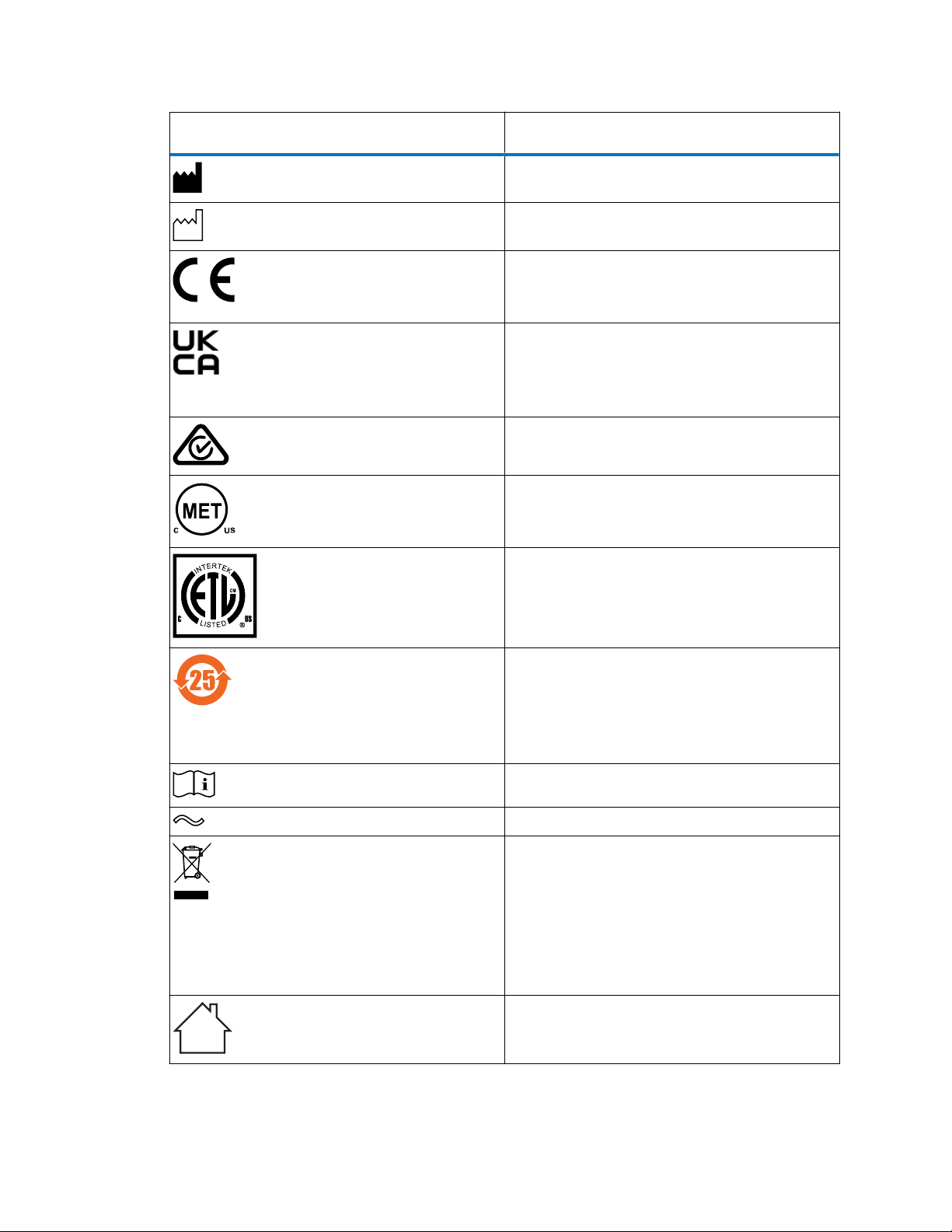
Symbol Definition
Manufacturer
Date of manufacture
Confirms that a manufactured product complies
with all applicable European Community
directives
UK Conformity Assessed marking confirms that
a manufactured product is in conformity with
the applicable requirements for products sold
within Great Britain
Australia EMC compliant
Confirms that a manufactured product complies
with all applicable United States and Canadian
safety requirements
Confirms that a manufactured product complies
with all applicable United States and Canadian
safety requirements
Environmentally friendly use period (China
RoHS): indicates the number of years from the
date of manufacture until the product, or
components within the product, are likely to be
discarded or degrade into the environment
Consult instructions for use
Alternating current
Electrical and electronic equipment with this
symbol may contain hazardous substances and
should not be disposed of as general waste
For compliance with the Waste Electrical and
Electronic Equipment Directive (WEEE)
2012/19/EU, contact Waters Corporation for the
correct disposal and recycling instructions
For indoor use only
December 16, 2021, 715007395 Ver. 00
Page vi
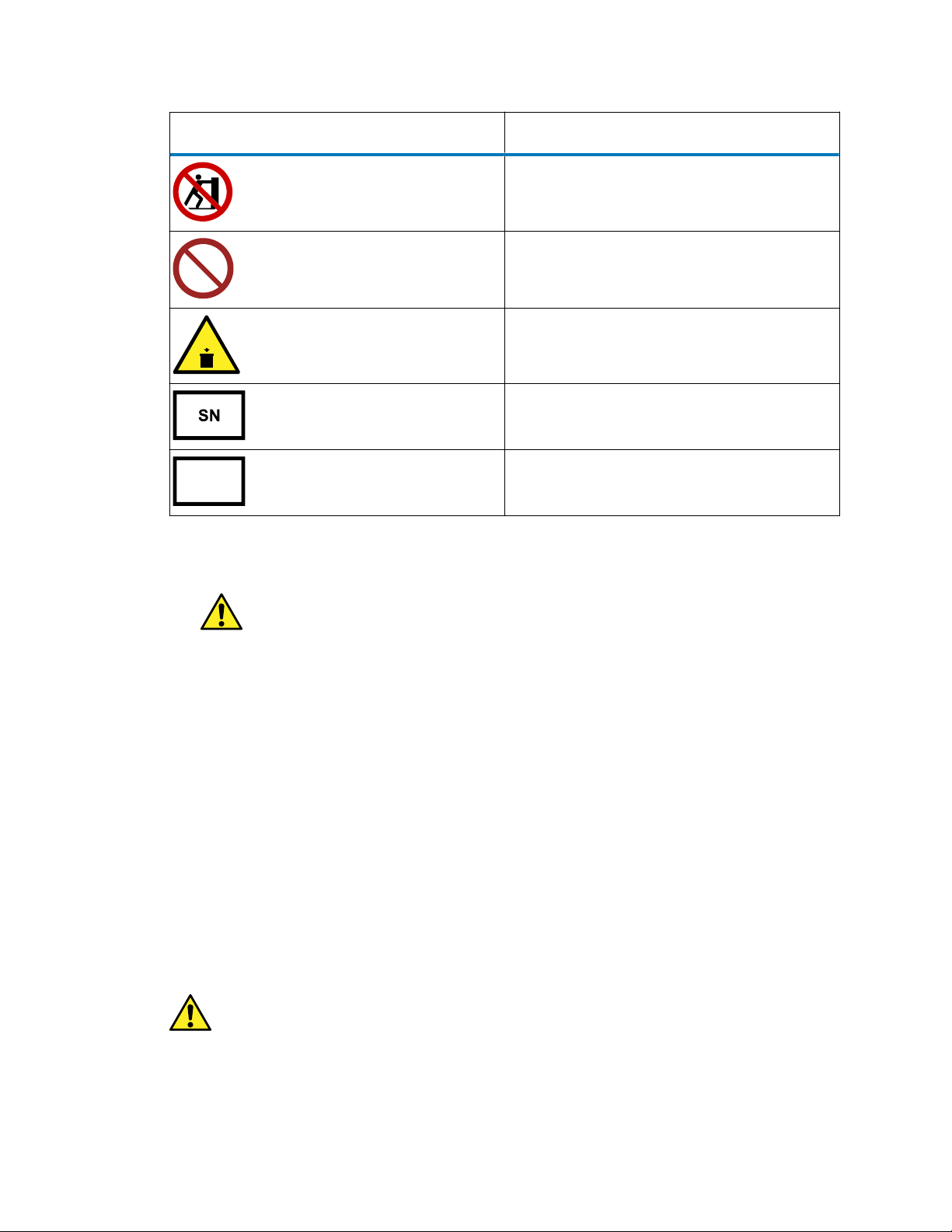
Symbol Definition
No pushing
LC
Do not connect to an LC system
10kg
max
Indicates the maximum load you can place on
that item (for example, 10kg)
Serial number
REF
Part number, catalog number
Safety hazard symbol notice
The symbol indicates a potential hazard. Consult the documentation for important
information about the hazard and the appropriate measures to prevent and control the hazard.
Electrical power safety notice
Do not position the device so that it is difficult to disconnect the power cord.
Equipment misuse notice
If equipment is used in a manner not specified by its manufacturer, the protection provided by the
equipment may be impaired.
Considerations specific to the device
Working environment and safety
This instrument's intended use is to detect electroactive substances in liquid samples in
combination with a UPLC or HPLC system in a GLP-approved environment. Operators using the
December 16, 2021, 715007395 Ver. 00
Page vii
system require experience, the appropriate education, and an extensive understanding of GLP
rules. To avoid unsafe situations, use this system only for its intended use.
System operation
To ensure optimal performance, Waters recommends that you inspect the detector and carry out
maintenance procedures regularly. Preventive maintenance contracts are available for that
purpose. Contact your local dealer or the nearest sales office for more information.
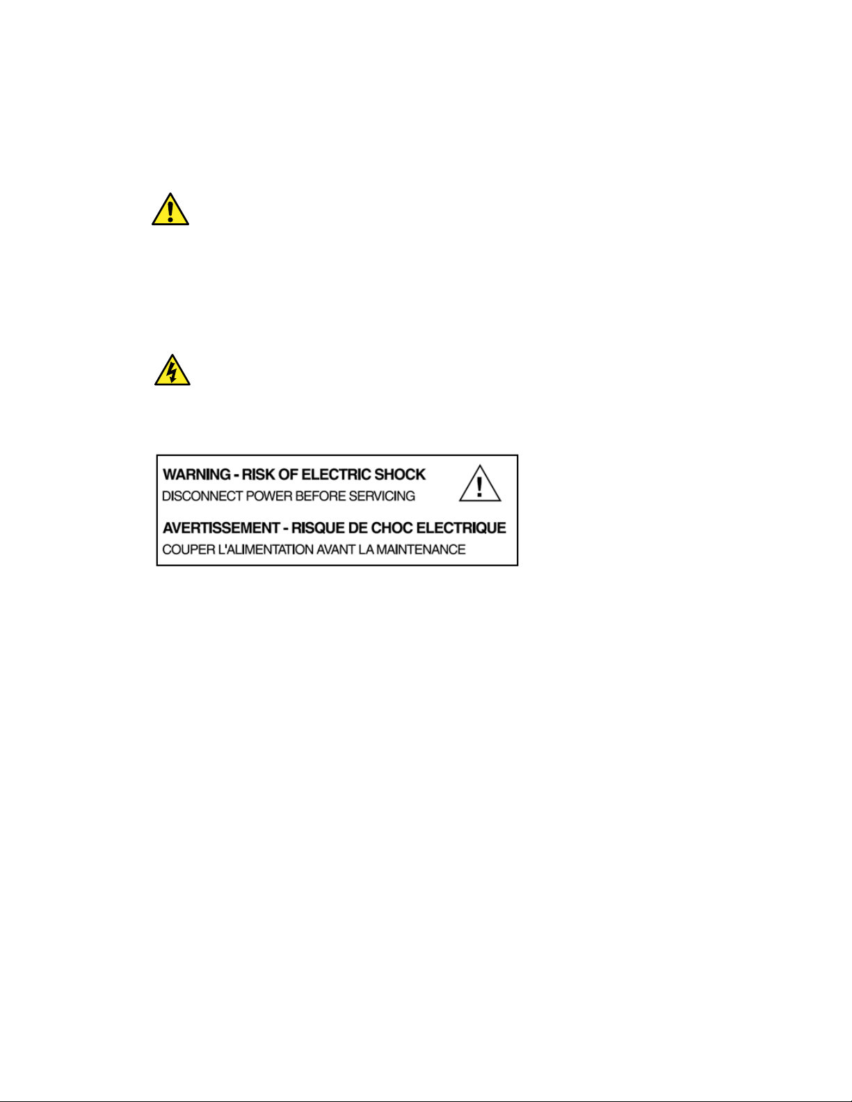
Electrical safety
Warning: To avoid electric shock, do not remove protective panels from the device.
The components within are not user-serviceable.
The removal of protective panels on the instrument can result in exposure to potentially
dangerous voltages. Disconnect the device from all power sources before disassembly.
Untrained personnel should not open the instrument. This may only be done by authorized
service engineers. Replace or repair faulty insulation on power cords immediately after discovery
of the fault. Confirm that the actual power voltage is the same as the voltage for which the
instruments are wired. Ensure that power cords are connected to correct voltage sources:
grounded AC power source, line voltage 100 – 240 VAC. Connect the instrument to a protective
earth via a ground socket. Only use the 3465 ECD with appliances and power sources with
proper protective grounding to prevent damage through build-up of static electricity. The power
source should exhibit minimal power transients and fluctuations. If necessary, connect to a
filtered mains socket.
December 16, 2021, 715007395 Ver. 00
Page viii
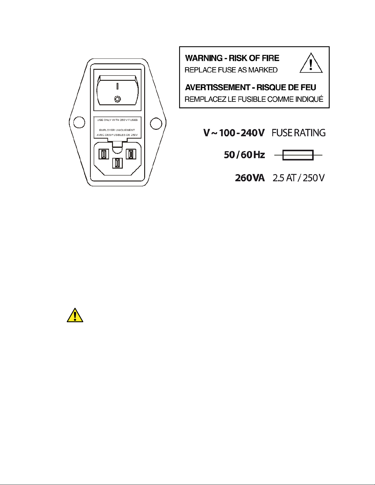
Replace blown fuses with fuses of the proper type and rating as indicated on the rear panel and
as noted in the list of accessories and spares. The fuse holder is integrated in the mains
connector. Ensure that the instrument is never put in operation with fuses of a different type. This
could cause fire.
Note: Only use manufacturer-supplied I/O cables to connect with other devices.
Thoroughly connect shielding to common. Manufacturer will not accept any liability for damage,
direct or indirect, caused by connecting this instrument to devices and with cables that do not
meet relevant safety standards. Place the detector on a flat, smooth surface. Do not block the
ventilation holes located at the bottom and lower rear panel of the detector. Blocking these holes
may impair the cooling capability of the power supply.
Solvents
The solvents used may be flammable, toxic, or corrosive. To prevent injury:
• Do not use an open flame near the device.
• Do not install the system in the same room with other equipment that emits or could
potentially emit sparks.
• Provide protective equipment near the instrument.
• When solvent gets into the eyes or on the skin, flush it away immediately.
• Provide equipment, such eye wash stations and safety showers, as close to the system as
possible.
• Use proper eye and skin protection when working with solvents.
• Seal sample containers (vials) to minimize any risks related to solvent vapor.
December 16, 2021, 715007395 Ver. 00
Page ix
Additional safety requirements or protection may be necessary depending on the chemicals used
in combination with this equipment. Ensure that you understand the hazards associated with the
chemicals and take appropriate measures with regards to safety and protection.
Biological hazard
When you analyze biological fluids, you must take all possible precautions and treat all
specimens as potentially infectious. To avoid personal contamination with biologically hazardous,
toxic, or corrosive materials, and to avoid spreading contamination to uncontaminated surfaces,
wear clean, chemical-resistant, powder-free gloves when performing procedures with the 3465
ECD.
Ventilation hazard
Warning: To avoid personal contamination with toxins and biologically hazardous materials
when using the system, follow appropriate safety precautions, and ensure adequate ventilation
and air exchange in the laboratory.
Waste disposal
Perform periodic leak checks on LC tubing and connections. Do not close or block the drain in
the oven compartment. Do not allow flammable or toxic solvents to accumulate. Follow a
regulated, approved waste disposal program. Never dispose of flammable or toxic solvents
through the municipal sewage system.
Safe disposal
Contact [email protected] with any questions or concerns regarding the proper handling or
disposal.
Dispose of Waters instrumentation products in accordance with applicable requirements and best
practices as described below.
• Follow appropriate procedures for flushing the instrument’s fluid paths of any hazardous
samples or solvents.
• Waters instruments are subject to European Union’s Waste Electrical and Electronic
Equipment (WEEE) and Restriction of Hazardous Substances (RoHS) Directives. According
to these directives, do not dispose of instruments in the general waste stream. Similar “e-
December 16, 2021, 715007395 Ver. 00
Page x

waste” laws also apply in other jurisdictions. In all cases, ensure that a certified electronics
recycler processes end-of-life instruments.
• Some Waters instruments use batteries, mercury-containing lamps, or other replaceable
components during the life span of the instrument. Handle such materials in accordance with
local laws governing their processing and safe disposal.
Applications: quality control
Routinely run three QC samples that represent subnormal, normal, and above-normal levels of a
compound. If sample trays are the same or very similar, vary the location of the QC samples in
the trays. Ensure that QC sample results fall within an acceptable range and evaluate precision
from day to day and run to run. Data collected when QC samples are out of range might not be
valid. Do not report this data until you are certain that the instrument performs satisfactorily.
Equipment misuse notice
If equipment is used in a manner not specified by its manufacturer, the protection provided by the
equipment may be impaired.
Safety advisories
Consult the "Safety advisories" appendix in this publication for a comprehensive list of warning
advisories and notices.
December 16, 2021, 715007395 Ver. 00
Page xi

Table of contents
General information........................................................................................................ii
Audience and purpose............................................................................................................................ii
Copyright notice......................................................................................................................................ii
Trademarks list....................................................................................................................................... ii
Customer comments..............................................................................................................................iii
Contacting Waters..................................................................................................................................iii
Intended use..........................................................................................................................................iv
EMC considerations...............................................................................................................................iv
FCC radiation emissions notice.......................................................................................................iv
Canada spectrum management emissions notice.......................................................................... iv
ISM classification: ISM group 1 class B........................................................................................... v
EMC emissions................................................................................................................................ v
Legal manufacturer.................................................................................................................................v
Safety considerations............................................................................................................................. v
Applicable symbols.......................................................................................................................... v
Safety hazard symbol notice.......................................................................................................... vii
Electrical power safety notice.........................................................................................................vii
Equipment misuse notice............................................................................................................... vii
Considerations specific to the device............................................................................................. vii
Safety advisories.............................................................................................................................xi
1 Introduction................................................................................................................19
1.1 Instrument description.................................................................................................................... 20
2 Installation..................................................................................................................24
2.1 Storage requirements ....................................................................................................................24
2.2 Site preparation requirements........................................................................................................ 24
2.2.1 Acquisition computer.............................................................................................................24
2.2.2 Laboratory requirements.......................................................................................................25
2.2.3 Electrical and power requirements........................................................................................26
2.2.4 Chemicals............................................................................................................................. 27
December 16, 2021, 715007395 Ver. 00
Page xii

2.3 Unpacking...................................................................................................................................... 27
2.4 Main power connection.................................................................................................................. 29
2.5 Connecting the Ethernet cable....................................................................................................... 29
2.6 Software......................................................................................................................................... 30
2.6.1 Dialogue Elite........................................................................................................................31
2.7 Fluidics connections....................................................................................................................... 32
2.7.1 Tubing connectors.................................................................................................................32
2.7.2 Mobile phase.........................................................................................................................34
2.7.3 Installation and startup..........................................................................................................35
3 Maintenance and shutdown......................................................................................39
3.1 Maintenance...................................................................................................................................39
3.1.1 Periodic check for leakage....................................................................................................39
3.1.2 Periodic check of the oven temperature............................................................................... 39
3.1.3 Flow cell................................................................................................................................39
3.1.4 Cleaning................................................................................................................................40
3.1.5 Replacement of fuses........................................................................................................... 40
3.2 Shutting down the system ............................................................................................................. 40
4 Detector controller.....................................................................................................42
4.1 Introduction.....................................................................................................................................42
4.2 Overview of 3465 Detector screens............................................................................................... 44
4.3 Parameters.....................................................................................................................................46
5 Detection and parameters.........................................................................................51
5.1 Introduction.....................................................................................................................................51
5.2 Three-electrode configuration........................................................................................................ 51
5.3 Internal organization.......................................................................................................................52
5.4 Dual flow cell control (optional)...................................................................................................... 52
5.4.1 Serial mode detection........................................................................................................... 53
5.4.2 Navigation in dual cell menu.................................................................................................53
5.5 Parameters.....................................................................................................................................54
December 16, 2021, 715007395 Ver. 00
Page xiii

5.5.1 Range................................................................................................................................... 54
5.5.2 Offset.................................................................................................................................... 55
5.5.3 Polarity..................................................................................................................................56
5.6 Filter............................................................................................................................................... 56
5.6.1 DC mode...............................................................................................................................56
5.6.2 Pulse mode...........................................................................................................................57
5.6.3 Pulse 2 mode (available in remote control only) ..................................................................57
5.7 Autozero.........................................................................................................................................57
6 Measurement modes................................................................................................. 59
6.1 DC mode........................................................................................................................................ 59
6.2 Pulse mode.................................................................................................................................... 60
6.3 Pulse mode 2................................................................................................................................. 61
6.4 Scan mode..................................................................................................................................... 62
7 Noise suppression - ADF.......................................................................................... 64
7.1 Introduction.....................................................................................................................................64
7.2 Frequency...................................................................................................................................... 64
7.2.1 Frequency of signal and noise..............................................................................................65
7.2.2 Low pass noise filters............................................................................................................67
7.2.3 Amplitude response plot....................................................................................................... 68
7.3 Applying ADF in chromatography...................................................................................................69
8 Pulsed amperometric detection (PAD).....................................................................72
8.1 Introduction.....................................................................................................................................72
8.1.1 Pulse mode versus DC mode............................................................................................... 72
8.1.2 High pH of mobile phase.......................................................................................................73
8.1.3 Pulse settings........................................................................................................................73
8.1.4 Optimization of wave forms...................................................................................................74
8.1.5 Output frequency.................................................................................................................. 74
8.1.6 Working electrode material................................................................................................... 75
8.1.7 References............................................................................................................................75
9 Optimization of the working potential..................................................................... 76
December 16, 2021, 715007395 Ver. 00
Page xiv

9.1 Introduction.....................................................................................................................................76
9.2 Electrochemical reactions.............................................................................................................. 76
9.3 Hydrodynamic and scanning voltammograms............................................................................... 77
9.3.1 Hydrodynamic voltammogram.............................................................................................. 77
9.3.2 Scanning voltammogram...................................................................................................... 77
9.4 Optimization using a voltammogram.............................................................................................. 78
9.5 Construction of a hydrodynamic voltammogram............................................................................ 79
10 3465 Detector specifications.................................................................................. 81
10.1 Environmental, dimensional, weight, and power requirements.................................................... 81
10.2 3465 General................................................................................................................................82
10.3 3465 DC Mode............................................................................................................................. 82
10.4 3465 PULSE mode.......................................................................................................................83
10.5 3465 PULSE mode 2....................................................................................................................83
10.6 3465 SCAN mode........................................................................................................................ 83
11 Rear panel I/O...........................................................................................................85
11.1 USB B connector..........................................................................................................................85
11.2 LAN connector..............................................................................................................................86
11.3 Digital I/O connector..................................................................................................................... 86
11.3.1 TTL inputs and outputs....................................................................................................... 86
11.3.2 Relays................................................................................................................................. 86
11.3.3 Aux......................................................................................................................................87
11.3.4 Overload..............................................................................................................................87
11.3.5 Cell on Cell off.....................................................................................................................88
11.3.6 Autozero..............................................................................................................................88
11.3.7 3465 Start............................................................................................................................88
11.4 Chassis grounding stud................................................................................................................ 89
12 Troubleshooting.......................................................................................................91
12.1 Instrument errors.......................................................................................................................... 91
December 16, 2021, 715007395 Ver. 00
Page xv

12.1.1 Erratic cell current value or offset after current compensation............................................93
12.2 Analytical troubleshooting............................................................................................................ 93
12.3 Dummy cell test............................................................................................................................93
12.3.1 External dummy cell............................................................................................................93
12.3.2 Internal dummy cell.............................................................................................................95
12.4 Stop flow test................................................................................................................................95
12.4.1 Possible solutions for analytical problems ......................................................................... 97
13 Detector accessories.............................................................................................100
13.1 Detector accessory kit................................................................................................................ 100
13.2 Optional AD converter cables.....................................................................................................100
14 FlexCell................................................................................................................... 102
14.1 The FlexCell............................................................................................................................... 102
14.1.1 Introduction....................................................................................................................... 102
14.1.2 The three-electrode configuration.....................................................................................103
14.1.3 Requirements and limitations ...........................................................................................104
14.1.4 Working electrodes........................................................................................................... 104
14.1.5 Reference electrode..........................................................................................................105
14.2 General precautions................................................................................................................... 109
14.3 Installation...................................................................................................................................110
14.3.1 Connecting a FlexCell to an LC system............................................................................ 111
14.4 Maintenance............................................................................................................................... 112
14.4.1 Disassembly of the flow cell.............................................................................................. 112
14.4.2 Working electrode cleaning ..............................................................................................114
14.4.3 Polishing a working electrode........................................................................................... 114
14.4.4 Flattening a metal working electrode................................................................................ 114
14.4.5 HyREF and ISAAC reference electrodes.......................................................................... 115
14.4.6 Salt bridge Ag/AgCl reference electrode...........................................................................115
14.4.7 Salt bridge Ag/AgCl reference electrode check................................................................ 116
14.4.8 Refilling a salt bridge Ag/AgCl reference electrode...........................................................117
14.4.9 Refritting a salt bridge Ag/AgCl reference electrode......................................................... 118
14.4.10 Assembly of the flow cell.................................................................................................119
14.5 Specifications............................................................................................................................. 120
14.6 Parts list......................................................................................................................................121
December 16, 2021, 715007395 Ver. 00
Page xvi

15 SenCell....................................................................................................................123
15.1 The electrochemical flow cell..................................................................................................... 123
15.1.1 Introduction....................................................................................................................... 123
15.1.2 Three-electrode configuration...........................................................................................123
15.1.3 Working electrode.............................................................................................................124
15.1.4 Detection limit................................................................................................................... 125
15.1.5 Cell working volume adjustment....................................................................................... 127
15.2 Reference electrodes................................................................................................................. 131
15.2.1 ISAAC reference electrode............................................................................................... 131
15.2.2 Salt bridge Ag/AgCl reference electrode...........................................................................133
15.2.3 HyREF reference electrode.............................................................................................. 134
15.3 Installation.................................................................................................................................. 134
15.3.1 Introduction ...................................................................................................................... 134
15.3.2 Adjusting the SenCell working volume..............................................................................135
15.3.3 Installation in LC system...................................................................................................136
15.3.4 Installing the SenCell........................................................................................................ 136
15.4 Maintenance ..............................................................................................................................140
15.4.1 Assembling/disassembling the cell .................................................................................. 140
15.4.2 HyREF ............................................................................................................................. 142
15.4.3 ISAAC............................................................................................................................... 142
15.4.4 Ag/AgCl salt bridge........................................................................................................... 144
15.4.5 Working electrode.............................................................................................................146
15.5 Specifications............................................................................................................................. 148
15.6 Parts list......................................................................................................................................149
16 VT-03 flow cell........................................................................................................ 150
16.1 The FlexCell............................................................................................................................... 150
16.1.1 Introduction....................................................................................................................... 150
16.1.2 Three-electrode configuration...........................................................................................152
16.1.3 Working electrode.............................................................................................................154
16.1.4 Detection limit .................................................................................................................. 154
16.1.5 Working electrode diameter..............................................................................................156
16.1.6 Spacer thickness ..............................................................................................................157
16.2 Reference electrodes................................................................................................................. 159
16.2.1 ISAAC reference electrode............................................................................................... 159
16.2.2 Salt bridge Ag/AgCl reference electrode...........................................................................163
December 16, 2021, 715007395 Ver. 00
Page xvii

16.2.3 HyREF reference electrode.............................................................................................. 163
16.3 Installation.................................................................................................................................. 164
16.3.1 VT-03 flow cell with HyREF or ISAAC...............................................................................164
16.3.2 VT-03 flow cell with salt bridge REF................................................................................. 165
16.3.3 VT-03 micro flow cell.........................................................................................................168
16.4 Maintenance ..............................................................................................................................175
16.4.1 HyREF.............................................................................................................................. 175
16.4.2 ISAAC............................................................................................................................... 175
16.4.3 Ag/AgCl salt bridge........................................................................................................... 176
16.4.4 Working electrode.............................................................................................................179
A Safety advisories.....................................................................................................181
A.1 Warning symbols..........................................................................................................................181
A.1.1 Specific warnings................................................................................................................182
A.2 Notices.........................................................................................................................................183
A.3 Bottles Prohibited symbol............................................................................................................ 184
A.4 Required protection......................................................................................................................184
A.5 Warnings that apply to all Waters instruments and devices.........................................................184
A.6 Warnings that address the replacement of fuses.........................................................................188
A.7 Electrical symbols........................................................................................................................ 190
A.8 Handling symbols.........................................................................................................................191
December 16, 2021, 715007395 Ver. 00
Page xviii

1 Introduction
Congratulations on your purchase of the 3465 Detector. This detector enables you to perform all
LC/UPLC applications using electrochemical detection. The 3465 Detector includes a highly
stable Faraday-shielded oven compartment accommodating column and flow cell. The flow cell
provides an unsurpassed S/N ratio for extremely sensitive electrochemical analyses. The 3465
Detector has three operational measurement modes: DC, SCAN, and PULSE. For a few specific
applications, the 3465 Detector can support up to two flow cells (optional).
December 16, 2021, 715007395 Ver. 00
Page 19
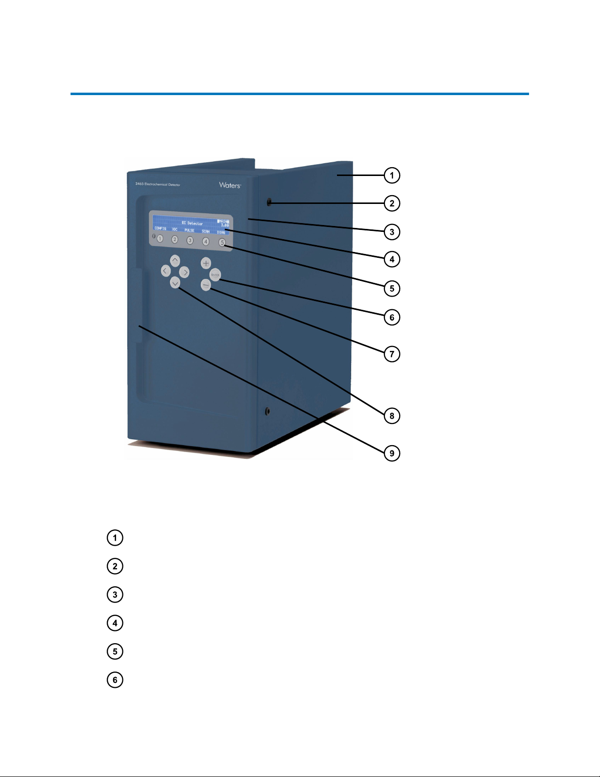
1.1 Instrument description
Figure 1–1: 3465 Detector - Front side
Instrument housing
LC tubing inlet/outlet
Instrument door panel
4 x 40 Ch LCD display
Function keys
<Enter> key
December 16, 2021, 715007395 Ver. 00
Page 20
Table of contents
Popular Laboratory Equipment manuals by other brands


Hamilton Beach
Hamilton Beach 74251 Read before use

Accuris
Accuris SmartDoc 2.0 instruction manual

Konica Minolta
Konica Minolta DRYPRO 793 brochure

Ocean Optics
Ocean Optics USB2000 Plus Installation and operation manual

Thermo Scientific
Thermo Scientific iCAP Q operating manual

THORLABS
THORLABS Redstone OSA305 quick start guide

cavitation
cavitation RF SUPER user manual

MELAG
MELAG Vacuklav 31 B+ user manual

Koehler
Koehler K70 Series Operation and instruction manual

Agilent Technologies
Agilent Technologies 75000 Series C User's guide and service manual

R-Biopharm
R-Biopharm RIDA qLine autoBlot user manual

Memmert
Memmert ICOmed 50 operating manual