WaterSoft G9P User manual

Filter Manual
Installation / Operation Manual
Fully Automatic
Water Filter
with 2092 Isobar Control Valve

Filter Specifications.................................................................................................Page 3
Installation Requirements.......................................................................................Page 4
Installation Procedures...........................................................................................Page 6

WARNING
Lubricants
Do NOT use Vaseline, oils, hydrocarbon lubricants or spray silicone anywhere! Petroleum base lubricants will cause
swelling of o-rings and seals. The use of other lubricants may attack plastic Noryl®. It is recommended that Dow
Corning® silicone grease be used as a lubricant for all control valves. Dow Corning® 7 Release Compound is used in the
manufacture of Chandler Systems control valves. (Part # LT-150)
Sealants
Pipe dope and liquid thread sealers may contain a carrier that attacks some plastic materials. It is recommended that
Teflon® tape be used to seal plastic Noryl® threaded fittings.
Filter Specifications
3
General Specifications G9P G10P G12P G13P
Filtration1Less Filter Media
Filter Media Capacity (cu ft) 1.0 1.5 2.0 2.5
Mineral Tank (Vortech ™) 9 X 48 10 X 54 12 X 52 13 X 54
Service Flow Rate - Continuous2(gpm) 4568
Service Flow Rate - Intermittent2(gpm) 6 7 8 10
Backwash Flow Rate3(gpm) 5.0 5.0 7.0 7.0
Gallons Used / Backwash 130 130 156 182
Space Required 9 X 9 X 56 10 X 10 X 62 12 X 12 X 60 13 X 13 X 62
Approximate Shipping Weight (lbs) 27 32 35 40
Filter Media Selection Guide
Media Description Handles
Neutralizer Granular / White / Sacrificial to water with pH < 7.0 /
Max pH correction to 7.2 / Lowest pH application 5.8 /
Must be replenished about every 3-6 months
Sediment
pH Correction
Granular
Activated
Carbon
Granular / Black / Wide application for removal of
organic and some inorganic / Must be replenished on a
regular basis / Life expectancy varies based on use
Sediment
Taste / Odor / Color
Chlorine / Iodine
Neu-Cor™ 70% neutralizer / 30% Corosex™ mix / Sacrificial to
water with any pH / Max pH correction determined by
contact time used for correction of extremely low pH
down to 5.0 / Must be replenished every 3 - 6 months
Sediment (downflow)
pH Correction
Filter Ag™ Granular / Off-White / Wide application for removal of
sediment / Life expectancy is unlimited
Sediment
Filter Ag™ Plus Light tan to near white in color / Mesh size 14 x 40 /
55 lb/ft3 / The Filter Ag Plus filter beds operate at less
than half the hydraulic loading rate vs. 20 x 40 mesh
sand and 50% of sand / anthracite or multi-media
Enhanced Particle Removal
(down to 5 microns)
Installation
4
Installation Requirements
A level floor position ahead of piping into water heater.
Unit must be installed at least 10 feet ahead of the inlet to a water heater to prevent damage due to back-up hot water.
DO NOT install the unit in an area of direct sunlight or where freezing temperatures may occur!
Locate the unit near an unswitched, 120 volt / 60 Hz grounded electrical outlet.
Check for distance and proper drain installation (e.g. floor drain, washing machine standpipe).
Determine type and size of piping required for filter connection (e.g. copper, galvanized, PVC plastic).
Note: If household plumbing is galvanized and you intend to make the installation with copper (or vice versa), obtain
di-electric unions to prevent dissimilar metal corrosion.
Note: Where the drain line is elevated above the control valve or exceeds 20 feet in length to reach the drain, use 3/4"
I.D. drain line tubing instead of 1/2" I.D. Drain line tubing is not included.
Caution: If sweat soldering copper pipe (remember to always use lead free solder and flux), cover yoke and bypass valve
with wet rags to prevent heat damage to connections and control valve. If using PVC or plastic pipe, primers and
solvent cements specifically recommended for use with potable water are required.
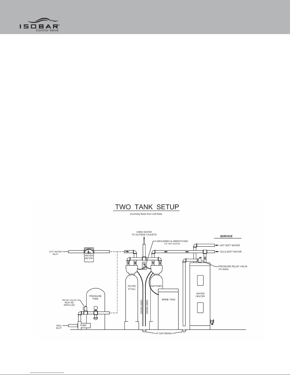
Note: All plumbing lines not requiring “soft” water should be connected “upstream” of the softener, if installed.
(See Typical Installation Diagrams.)

Installation Installation
5
Installation Procedure
- Water Supply Connection and Bypass Valve -
To allow for filter servicing, swimming pool filling or lawn sprinkling, a manual Bypass Valve has been installed at the
factory. The Bypass allows raw water to be manually routed around the filter.
1. Position filter at desired location for installation. If a water softener is to be installed, the filter should be positioned first
and then the softener. (See Installation Diagrams.)
2. The filter material is shipped separately from the mineral tank. The tank must be loaded with material after tank has
been placed at the desired location.
A. Remove the control valve by unscrewing from the tank.
B. Use plug provided to place over top of distributor tube to prevent material from entering tube while filling.
C. Place media funnel in hole on top of tank.
D. Pour several gallons of water in the tank. (Fill tank about 1/3 full.)
E. Pour in the required filter media. No gravel is required. The required quantity of media is listed in the filter
specifications.
Note: If rebedding an existing unit and the system utilizes a standard tube & basket style distributor, a “D” gravel under
bedding will be required.
F. After filling the tank with material, use a garden hose or several buckets to fill the tank with water.
Note: This will permit the filtering media to become soaked while preparing the installation and will prevent the control
valve from being plugged with floating material on initial backwash.
G. Remove funnel and clean filter media from tank threads.
H. Remove plug from distributor tube.
I. Replace control valve on mineral tank.

Installation
6
Caution: Be extremely careful to position distributor tube into control valve distributor tube pilot hole.
3. Turn OFF main water supply and OPEN nearest faucet to relieve pressure.
4. Cut main line and install appropriate elbows and extensions.
Caution: Raised arrows located on the sides of control valve body and bypass valve indicate proper direction of water
flow. Install inlet and outlet piping in direction of arrows.
- Drain Line Connection -
1. Remove drain line hose barb and wrap threads with Teflon tape. Reinstall drain line hose barb
Caution: Hand tighten only!
2. Install 1/2” I.D. drain line tubing (not included) from hose barb to an open drain. A 4” gap between end of the drain line
and the open drain is required to prevent waste water backflow. Keep the drain line as short as possible. An overhead
drain line can be used if necessary, but should discharge below the control valve. A syphon trap (taped loop) at the outlet
of the drain line is advisable to keep the drain line full and assure correct flow during backwash. Elbows or other fittings
must be kept at a bare minimum.
Note: Where the drain line is elevated above the control valve or exceeds 20 feet in length, 3/4” I.D. drain line tubing
should be used.
- Electrical Connection -
1. Connect the power cord and plug into a 115 volt / 60 Hz receptacle.
Note: Do not plug into an outlet controlled by a wall switch or pull chain that could inadvertently be turned off
Installation Procedures
1. Move the bypass valve slowly to the Service position or open the main valve and allow water to flow to the mineral tank.
2. When the water stops flowing into the tank, open a treated water tap and allow air to be released from the lines. Then
close the tap. Open the bypass valve or main valve completely.
3. Rotate the manual regeneration knob clockwise to the “backwash” position. On all units except a carbon filter allow to
backwash the factory preset time of 10 minutes or until water becomes clear at the drain. This will wash out the fine
material from the mineral. Check water at drain to be certain large quantities of mineral are not being lost. If mineral
is still flowing out return the controls to “Service” position and allow mineral to soak longer before being backwashed.
Anytime media - other than very fine mineral on initial startup - is apparent in the service lines, it usually indicates one of
the following problems:
A. The unit is plumbed in backward allowing the media to be carried in the service line.
B. The distributor tube inside the tank is not seated inside the valve or is damaged in some way. If the media continues
to flow to the drain during backwash after a reasonable period of soaking, check the drain line flow control to be sure
that excessive water is not going to the drain allowing mineral to siphon out of the tank.

Installation Installation
7
4. Set the days of backwash desired and the time of day as follows:
How to set the day on which the water filter is to backwash: Rotate the skipper wheel until the number “1" is at the
red pointer. Set the days that the backwash is to occur on by sliding tabs on the skipper wheel outward to expose trip
fingers. Each tab is one day. Finger at red pointer is tonight. Moving clockwise from the red pointer, extend or retract
fingers to obtain the desired backwash schedule. (See diagram.) If you want to backwash every day, you would slide all
the tabs out. Every other day would extend out tab numbers 2, 4, 6, 8, 12 (or 6 tabs). Every three days would extend tab
numbers 3, 6, 9, 12 (or 3 tabs). Every 6 days would extend tab numbers 6 & 12 (or 2 tabs). Every 12 days would extend
tab number 12 only.
How to set the time of day: Press and hold the black button on the left side of the control valve in to disengage the drive
gear. Turn the large gear (not the knob) in the center until the actual time of day appears in the “Time of Day” window at
the bottom. Release the black button to again engage the drive gear. Make sure the “AM” and “PM” is correct for your
situation. The starting time for backwash is preset to be about 1:00 a.m. the backwash and rinse cycles are also preset.
(See diagram.)
How to manually backwash your water filter at any time: Turn the manual backwash knob clockwise until you can
read “Start Cycle”. The unit will automatically continue through the backwash cycle and then return to the “In Serv”
position when complete.
- Final Checkout -
1. Be certain that the bypass valve is in Service position or main valve is completely on.
2. Check electrical supply to be certain the cord is connected to an uninterrupted 115 volt outlet.
3. Be certain the warranty card is filled out and mailed in.
4. Leave this manual with the homeowner.
Important Notice - The plumbing system, piping, pressure tank, hot water tanks, softeners, etc. that have been exposed
to iron bearing water may need to be cleaned of the precipitated iron that has been collected in them or iron bleed thru
may be a problem. We suggest all tanks be drained and flushed thoroughly.

This manual suits for next models
3
Table of contents
Other WaterSoft Water Dispenser manuals


Popular Water Dispenser manuals by other brands

WeldTec
WeldTec C25 STANDARD owner's manual

Elkay
Elkay FLEXI-GUARD EFW Deluxe Installation, care & use manual

Puretec
Puretec SOL-E1 Series user guide

Lotus
Lotus Water Treatment System Use & care guide

Canature WaterGroup
Canature WaterGroup 85HE owner's manual

Crystal Mountain
Crystal Mountain Blizzard quick start guide


