Innowave uvf3 10-VMHC3 User manual
Operation
Manual
R
3201 Farnam Street
Omaha, NE. 68131-3406
1-800-288-1891
Rev. NC, October 1, 2003
Page 2
Operation Manual
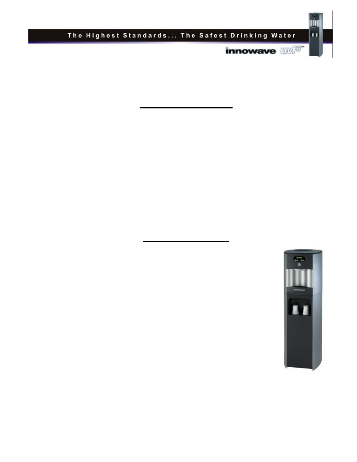
Congratulations on your choice of the innowave uvf3water dispenser. The innowave
uvf3dispenses both hot and cold water using modern multi-filter and ultraviolet (UV)
technologies.
The innowave uvf3puts an end to bottled water deliveries by filtering your customer’s own
water supply of contaminants and bacteria, leaving you with an endless supply of crystal clear,
filtered water.
Note: The innowave uvf3is not intended for use with water that is microbiologically unsafe
or of unknown quality without adequate disinfection before or after the system.
To ensure proper and efficient functioning of your innowave uvf3, carefully follow the
instructions contained in this manual.
Table of CONTENTS
•Specifications.................................................................................3
•Model and Part Designations .........................................................3
•Replacement Components..............................................................3
•Operational Instructions .................................................................4
•Programming Instructions..............................................................5
•Pre-Installation Procedures ............................................................7
•Installation procedures .................................................................12
•Safety precautions........................................................................14
•Six-month service.........................................................................14
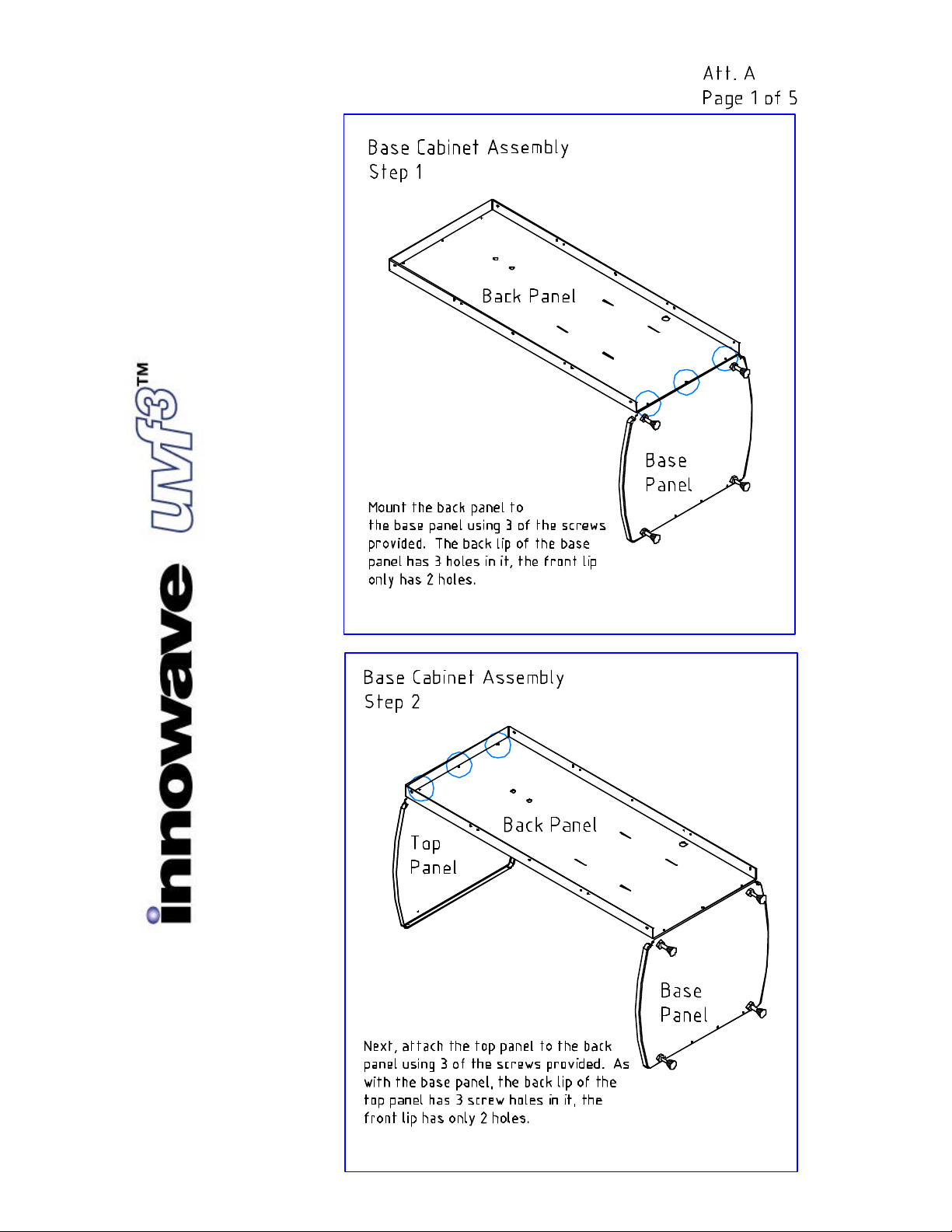
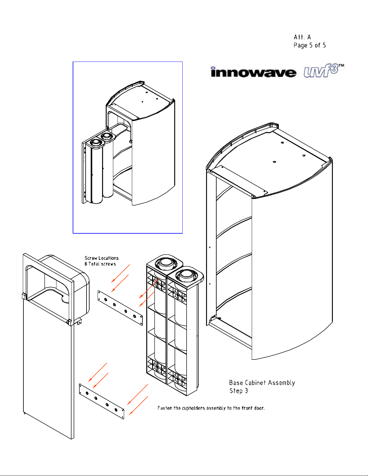
•Base Cabinet and Cupholders Assembly Instructions............ Att. A
•Refrigeration Schematic..........................................................Att. B
•Parts Breakdown Drawing.......................................................Att. C
•Parts Listing…………………………………………………Att. D
•Troubleshooting Guide…..(Future)

Rev.NC
October1,2003
Page 3
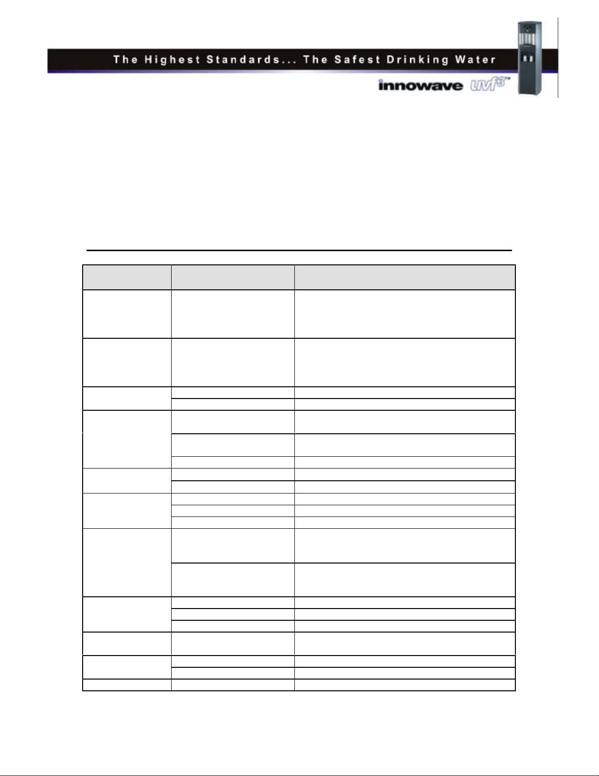
SPECIFICATIONS
ITEM Mini Model (w/o Base Cabinet) Mini Model (w/ Base Cabinet)
Width/Depth/Height 17 x 18 x 18.5 in. 17 x 17 x 49.25 in.
Water Connection 1/4 in. tubing Same
Cold Water Temperature 37°- 54°F adjustable
3°- 12°C adjustable Same
Hot Water Temperature 158°- 203°F adjustable
70°- 95°C adjustable Same
Recommended Service Pressure 40-60 psi (275-414 kPa) Same
Max. Working Pressure 60 psi (414 kPa) Same
Rated Service Flow† 0.5 gpm (1.89 lpm) Same
Temperature 50-95°F (10-35°C) Same
Weight 102 lb. (46.3 kg) Same
Electrical Supply 120V/60Hz Same
Control and Unit 2.05 amps Same
Heater 6.9 amps Same
Total 8.95 amps Same
Refrigerant R134a
Hi (128-142 psi) Low (14-21 psi) Same
ANSI/NSF Std. 42
(hot and cold outlets)
Chlorine Reduction
Particulate Reduction
Taste/Odor Reduction Same
† Limited to 0.5 gpm by the filter head installed on the 1 micron carbon block filter.
Model/Part Designations:
Model/Part Number Description
10-VMHC3 innowave uvf3, mini unit, Hot and Cold, with double-cold tank technology
10-7000 Base Cabinet, for innowave uvf3
10-7001 Upgrade Kit, Cupholders, for Base Cabinet
REPLACEMENT COMPONENTS
Component Part No. Frequency of Replacement
UV Light, TUV-8W 10-7020 Every 6 months, or as required
UV Quartz Sleeve 10-1400 Clean every 6 months, replace as needed
10” Twist GAC filter, with
Polyphosphate Additive to Reduce
Scaling, Reverse-Threaded Design 10-7002 Every 6-months, or as required
10” Twist Carbon Block Filter,
1-Micron, Reverse-Threaded Design 10-2801 Every 6-months, or as required
Replacement parts can be obtained from your authorized innowave dealer.
Rev.NC
October1,2003
Page 4
Operational Instructions
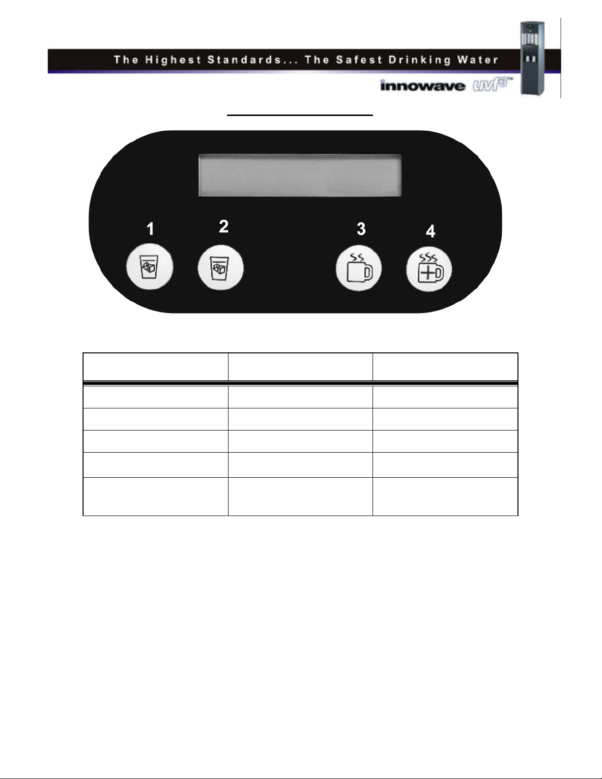
The above picture shows the front display and control panel for the innowave uvf3.
Button No. Operational Use Programming Use
1Select Cold Water Scroll the Menu Down
2Select Cold Water* Scroll the Menu Up
3Select Hot Water Enter an Option on the Menu
4Select Extra Hot water Escape to Main Menu/Exit
Programming Mode
Main Button
(not shown above) Dispense Selection N/A
* In Europe, Button No. 2 is used operationally to select sparkling water (CO2).
For Cold Water: Press button 1 (or Button No. 2) followed by the main dispensing button.
Note that either Button No. 1 or No. 2 select cold water.
For Hot Water: Press Button No. 3 followed by the main dispensing button.
For Extra Hot Water: Press Button No. 4, wait approximately 60 seconds, then press the main
dispensing button. This procedure will raise the hot water temperature
approximately 5 degrees. Repeating the process over again will raise the
temperature about 5 more degrees until the desired temperature is
reached up to 207 degrees Fahrenheit.
Note: The default mode is cold water. The program will return to cold water after 5 seconds of
the selection made.

Rev.NC
October1,2003
Page 5
Programming Instructions
Refer to the Table on Page 4 for functions of the buttons on the front display panel.
To access the programming menu, depress Buttons No. 1 and No. 2 simultaneously for three
seconds until the message “Cold Temp Set” appears on the display.
Note: If no buttons are pressed within 5 seconds, the display will exit the programming mode
(i.e. “Cold”).
Programming Example:
Change the Language from English to Spanish:
1. Press Buttons No. 1 and No. 2 for three seconds until “Cold Temp Set” appears
on the display.
2. Press Button No. 2 repeatedly until the menu scrolls to the option “Language”
on the display.
3. Press Button No. 3 to select the option.
4. Press Button No. 2 repeatedly to scroll down through the languages (English,
Spanish, and French).
5. Press Button No. 3 to select “Spanish.”
6. Press Button No. 4 to exit programming mode.
Programming Example:
Change the Language from Spanish to English, and lower cold temperature to 37°F:
1. Press Buttons No. 1 and No. 2 for three seconds until “Cold Temp Set” appears on
the display.
2. Press Button No. 2 repeatedly until the menu scrolls to the option “Language” on the
display.
3. Press Button No. 3 to select the option.
4. Press Button No. 1 repeatedly to scroll up through the languages (Spanish, French,
and English).
5. Press Button No. 3 to select “English.”
Rev.NC
October1,2003
Page 6
6. Press Button No. 1 repeatedly until the menu scrolls up to the option “Cold Temp
Set” on the display.
7. Press Button No. 3 to select the option.
8. Press Button No. 1 repeatedly until “37F” is displayed.
9. Press Button No. 3 to select “37F.”
10. Press Button No. 4 to exit Programming mode.
Menu Options Brief Description
Cold Temp Set 3°- 12°C
37°- 54°F
The cold temperature can be set between 3°C and
12°C or 37°F and 54°F, depending on which units
are selected (°C or °F) in the F/C option.
Recommended setting is 5°C/41°F.
Hot Temp Set 70°C - 95°C
158°F - 203°F
The hot temperature can be set between 70°C and
95°C or 158°F and 203°F, depending on which units
are selected (°C or °F) in the F/C option.
Recommended setting is 87°C/189°F.
Static The display indicates the SET temperature.
Temp Display Ranging The display indicates the ACTUAL tank temperature
3 minutes The uv lamp lights every time you take a drink of
cold water, and stays on for 3 minutes.
10 minutes The uv lamp lights every time you take a drink of
cold water, and stays on for 10 minutes.
UV Timer
Constant The uv lamp is lit at all times when power is on.
°CTemperatures are displayed in degrees Fahrenheit.
F/C °FTemperatures are displayed in degrees Centigrade.
English The display will read in English
French The display will read in FrenchLanguage Spanish The display will read in Spanish
Liters (4000-9000) Calculates the water dispensed in liters. When the
water dispensed reaches the set amount, an alarm
will sound for servicing.
Flow Counter
Gallons (1000-3000) Calculates the water dispensed in gallons. When the
water dispensed reaches the set amount, an alarm
will sound for servicing.
3 months Timer for Filter Life set at 3 months
6 months Timer for Filter Life set at 6 monthsFilter Timer 9 months Timer for Filter Life set at 9 months
Filter Life Indicates the amount of water flowed, or months
elapsed.
On Shuts down hot water if not used in 3 hours time.
Sleep Mode Off Hot water remains powered indefinitely
Default Defaults to Cold Not a Programmable Option to Date

Rev.NC
October1,2003
Page 7
PRE-INSTALLATION PROCEDURES
The sanitizing procedure that follows (steps 7-30) is required prior to installing the
innowave uvf3. Refer to Figure 2 on page 8 for correct disconnects and reconnections of
fittings. The materials required for the sanitizing procedure are listed below. All items
should be on hand prior to starting this process.
Materials needed:
•Phillips Screwdriver
•10” Filter Housing fitted with ¼” John Guest fittings (Use John Guest fittings PI-
010822S), or stem adapters (PI-0308S)/unions (PI-050822S).
•5 gallon Carboy
•Household Bleach (5.25% Sodium Hypochlorite)
•¼” Plastic Tubing, approximately 4 ft. in length.
•Test Strips for measuring chlorine free water in pools/spas.
•1/8” NPT Female Thread to ¼” compression Fitting (Used to connect to drain fitting)
•Safety Gloves and Protective Eyewear.
•Caution: Do not plug the unit into an electrical outlet until step 25.
1. Unpack the innowave uvf3and
check exterior for damage.
2. Remove the recessed screw that is
located directly in front of the faucet
nipple. Refer to Figure 1. Removing
this screw will allow access to the
inside serviceable components (filters
and uv light).
3. Hinge open the front cover by lifting
up and pulling out.
Filter Rinsing:
4. Remove the 2 filters that are inside the front cover. Remember that these filters are
reverse-threaded into beverage heads, and to remove them from those heads, you must
turn them clockwise.
5. Utilizing spare beverage heads from your shop, rinse the 2 filters thoroughly. We
recommend at least 5 gallons of fresh water be rinsed through the filters.

Rev.NC
October1,2003
Page 8
6. Once rinsed, install the filters back into the unit. The 10-2801 filter should be installed in
the filter port that is on the left side of the faucet (as you face the front of the machine).
The 10-7002 should be installed in the filter port on the right side of the faucet.
Machine sanitizing:
Note: This sanitizing procedure basically involves injecting water doped with 200 ppm
of chlorine into the cold-water drain line of the machine. This chlorinated water will
flow through the drain system into the cold tanks. When the cold tanks are filled with
water, the sanitizer will sit for 10 minutes before being flushed out of the system.
Flushing will involve fresh tap water flow into the back inlet fitting, through the faucet.
7. Remove the 4 screws
that secure the top cover
(top cover is different
than the access door you
opened in step 3).
Remove the top cover
and set aside.
8. Refer to Figure 2.
Remove the ¼” plastic
tube that connects the
outlet of the cold tank to
the inlet of the top
solenoid valve (outlet
solenoid) and set aside.
9. Connect a length of ¼”
tubing to the outlet of
the cold tank and route that tube to a sink, floor drain, or carboy. Caution: Wear Safety
Glasses. Secure the tubing sufficiently to prevent any unwanted repositioning or
movement. This is the tubing that will flow sanitizer solution when the tanks are
filled, and all necessary precautions need to be taken to prevent unwanted
sanitizations of eyes, clothing, and carpets.
10. Plug the tap water connection (inlet bulkhead fitting) that the tap water connects into on
the back of the machine (see the Figure on Page 9).
11. Remove the stainless steel cap off of the cold water drain line on the back of the machine.

Rev.NC
October1,2003
Page 9
12. Connect a length
of ¼” tubing from the
outlet fitting of the
10” filter housing to
the drain fitting of the
innowave uvf3. The
threads on the drain
fitting are 1/8” NPT,
and will require using
a 1/8” NPT female
thread to ¼”
compression fitting to
make the connection.
The fitting is
available at hardware
stores, and is the
same fitting used for
sanitizing the
innowave LF. Note
also that coating the threads of the drain fitting with Teflon tape will ensure that there is
no leakage from the connection during this sanitizing process.
13. Connect a length of ¼” tubing from the inlet of the filter housing to a tap water supply
connection.
14. In the filter housing, mix a 1-gallon solution of household bleach and water to make a
200-ppm concentration (will require approx. 1 tablespoon of household bleach). The
volume of the housing cannot facilitate 1 gallon of water, obviously, but 1 gallon of
solution will ultimately be made when step 15 (filling the cold tanks) is performed. Put
the bleach in the filter-housing, fill with water and stir.
15. Tightly close the filter housing.
16. Crack open the water supply valve to SLOWLY fill the tanks with sanitizer.
17. When the tanks have filled with sanitizer, the ¼” tubing that was connected to the outlet
of the cold tank (Step 8) will start to flow sanitizer to the drain. Once flow to the drain is
established, shut off the water supply.
18. Disconnect and remove the ¼” tubing that was installed on the outlet of the cold tank and
routed to a drain in Step 8.

Rev.NC
October1,2003
Page 10
19. Re-connect the original length of ¼” tubing that was removed in Step 7. Securely plug the tubing
into the cold tank outlet fitting, and into the inlet side of the solenoid.
20. Remove the ¼” tubing that was connected to the machine drain fitting in Step 11. Use a rag or
towel in this step to prevent spilling drops of sanitizer from the fitting when disconnected.
21. Re-install the stainless steel cap onto the machine drain fitting.
22. Allow the solution to remain in the cold tanks for a maximum of 10-15 minutes.
Flushing the Sanitizer From the Machine:
23. After a 10-15 minute soak of sanitizer in the machine, remove the plug on the inlet bulkhead
fitting on the back of the unit.
24. Install the tap water tubing into the inlet bulkhead fitting. Turn on the tap water supply.
25. Plug the machine into power, and turn on the red power switch on the back of the innowave
uvf3.
26. After waiting 10 seconds for the unit to perform its diagnostics checks, depress the main
dispensing button on the front control panel, and flush several gallons of water through the faucet
to dilute and remove the sanitizer. Please note: A pitcher or some other setup will be required
to catch the water as it flows from the faucet. Any spillage of the first 2 or 3 gallons of
water will effectively sanitize everything it touches, so use extreme care!
27. Once the chlorine odor has been flushed out of the machine, the sanitization process for the cold
tanks is complete. It would be advisable to test the water for chlorine content using chlorine test
strips.
Flushing the Hot tank:
28. Place a pitcher, catch basin, or other setup to catch water under the faucet of the machine.
29. Press the hot button (Button No. 3), followed by the main dispensing button to fill the hot tank.
30. When the hot tank is filled, water will begin dispensing from the machine through the faucet.
Continue flushing until 3 gallons have been dispensed.
UV System Functional Test:
31. Ensure power is on (Red switch is lit).
32. Open the front access cover by lifting up and pulling out.
Rev.NC
October1,2003
Page 11
33. Dim the overhead lights and peer into the machine, on top of the cold tank, at the uv connector
and retaining cap. The blue glow indicates that the lamp is lit.
34. Find the white wires delivering power to the top of the lamp assembly. Follow the wires back
until the electrical connector is found. Disconnect the electrical connector and verify that the uv
lamp alarm annunciates.
35. Reconnect the uv lamp wire connector, and cycle the red power switch to clear the alarm.
Compressor Test:
36. Switch on the green power switch (turns on the compressor and heater). When the compressor
starts, the fan condenser also will start. Verify the fan has started by feeling for the discharge of
air at the rear grill of the machine.
37. Monitor the displayed temperature on the front of the unit. The default cold water setting from
the factory is 41°F. At an ambient starting temperature of 75°F, it will take about 20 minutes for
the unit to chill down to 41°F.
38. Once the machine reaches its target temperature, draw a glass of cold water and verify it is has
been chilled.
Heater Test:
39. Assuming the green power switch has been turned on, and sufficient time has elapsed between
powering the green switch for the heater to operate (approximately 10 minutes), verify the hot
water system is working by dispensing hot water into a cup.
Draining the Machine for Transport:
40. If you need to drain the tanks of the innowave uvf3, please use the following precautions:
a. Prior to draining the hot tank, turn off the green compressor/heater switch, and dispense a
gallon of hot water from the machine. As hot water is dispensed from the faucet of the unit,
colder water will be introduced into the hot tank. Since the green power switch is turned off,
the heater will not energize and heat the incoming tap water. Following this precaution
prevents exposing drains, sinks, catch basin, etc. to scalding hot water.
b. When draining the cold tanks, you need to remove the ¼” tubing on the outlet of the cold
tank (located inside the access panel on the top front of the machine, which is the same tube
removed for sanitizing in step 8). Removing this tube creates a vent path in the tank that will
allow the cold tank water to drain. Also, if during the draining of the cold tanks, you find the
draining process restricted to just drips, chances are there is an inordinate amount of ice
accumulated in the tanks. Dispensing a gallon of cold water from the system, prior to
draining, should alleviate the problem.

Rev.NC
October1,2003
Page 12
INSTALLATION PROCEDURES
NOTE: Ensure installation of the innowave uv3®complies with all applicable state and local
regulations. The following installation procedures assume that you have performed the Pre-
Installation procedures and sanitization of the unit starting on Page 7 of this manual.
1. Place the innowave uvf3®on a firm, flat surface. Ensure that the water and electrical supplies
are located within 5 feet of the unit (do not use an extension cord with the innowave uvf3®).
Level the unit using the adjustable feet on the bottom of the innowave uvf3®.
2. Attach the water supply tube to the 1/4” feed water inlet on the back of the unit. innowave®
strongly recommends that a water pressure regulator, pre-set between 40-60 psi, be installed prior
to the inlet or bulkhead fitting into the unit.
3. Turn on the water supply and rinse the filters of any fines that may have dislodged during
transportation. Approximately 1-2 gallons is required for this procedure.
4. Check to ensure that both the red power switch and the green compressor switch are in the off
position.
5. Connect the power cord to the back of the innowave uvf3®and to a 120volt electrical outlet.
6. Turn the red power switch to the on position (I = On). Ensure that only the red power switch is
turned on and not the green compressor switch. If the green compressor switch is turned on
while the hot (if present) tank is empty, damage could occur to the tank in less than 1
minute.
7. Move the innowave uvf3®into its final operating position. Be sure that a minimum of 2”
clearance is maintained from both the sides and the back of the unit. This ensures that proper
airflow is maintained.
8. Open the water supply and check for leaks.
9. Holding a pitcher under the dispensing faucet, press and hold the main dispensing button until a
continuous flow of water is obtained. Once a continuous flow is obtained, release the dispensing
button.
10. Hold a pitcher under the dispensing faucet, press the hot button (Button No. 3) followed by the
main dispensing button until a continuous flow of water is obtained. Once a continuous flow is
obtained, release the main dispensing button.
11. Press the cold button and dispense cold water into the drip tray. Ensure that the drip tray alarm
will sound and the unit will shut down once the drip tray is full. Also check that the drip tray full
annunciation is present on the display.
Rev.NC
October1,2003
Page 13
12. Empty the drip tray and wipe dry. While the drip tray is unattached from the front panel dry the
alarm sensor connectors.
13. Check the unit for any leaks.
14. Turn the green compressor switch to the on position (I = On). Check for fan and compressor
operation. This can be done by listening to the unit when the green compressor switch is turned
on and/or visibly checking the fan.
15. After 15 minutes, the cold water should drop approximately one degree every 1-1/2 minutes. The
hot water will heat rapidly.
16. When the unit has reached its target temperature(s), the compressor will cycle off.
17. Once the unit is at the target temperature(s), press the cold button, verify that the UV lamp
operates as expected (no alarm annunciated on the display). Taste the water to ensure that
additional rinsing is not required.
18. If you choose to reconfigure the temperature display and UV light settings from the original
factory settings, refer to the Programming Instructions section of this manual.
Verifying the Program Settings:
19. The following defaults are programmed into the machine at the factory:
a. Cold Temp Set = 41°F
b. Hot Temp Set = 189°F
c. Temp Display = Ranging
d. UV Timer = On full-time
e. F/C = Fahrenheit
f. Language = English
g. Flow Counter = Gallons, 2000
h. *Filter Timer*
i. Sleep Mode = Off
Note about item ‘h’ in the above list: If you have paged through the menu and have entered
the field for item h, regardless of whatever selection you made, the flow counter will be
disabled, and filter life will be displayed in months rather than gallons. To reprogram the
flow counter, you will need to enter the field for item ‘g’, select it, and enter your options
(gallons and 2000). Once this action has been performed, do not enter the field for item ‘h’
again.

Rev.NC
October1,2003
Page 14
SAFETY PRECAUTIONS
•Keep small children away from the unit to avoid accidental pressing of the hot water buttons.
•When using the base cabinet in conjunction with the innowave uvf3, be sure to lock the 2
components together with the wing nut provided in the base cabinet packaging prior to leaving
the installation site.
•If it becomes necessary to reset the thermal overload on the hot tank, the top cover, and right-side
panel will need to be removed for access. Prior to actually resetting the overload, make sure the
power cord has been unplugged from the machine.
SIX-MONTH SERVICE
1. It is recommended that the UV lamp be changed every 6 months. At this time, the quartz sleeve
around the UV bulb should also be rinsed off with water and wiped with a non-abrasive cloth.
The hot tank may be de-scaled or replaced if necessary.
2. Check the black O-ring on the quartz sleeve for any signs of wear or damage. Replace as
necessary.
3. The filters should be replaced every 6 months, or 2000 gallons, whichever comes first.
4. Flush 5 gallons of water through the filters. This is done to ensure that the new filters are rinsed.
Do not rinse the filters through the Solenoid Valve(s).
5. Check to make sure there is a 2” clearance around the unit.
6. Clean the condenser grill and compressor fan.
7. Inspect all electrical and water connections.
8. Test the drip tray overflow function. Clean and dry off the drip tray sensors.
9. Test that the UV sensor is working.
10. Check for leaks.
11. Check to see if the unit is running to the customer’s satisfaction.

Rev. NC
October 1, 2003
Page 15
Fault Codes and Displays
Indication Action
The display indicates:
“Change Filter”
Replace the filter. Either the gallons
setting or the filter timer (months) setting
has expired. Reset the machine once filters
are replaced.
The display indicates:
“Drip Tray Full” Empty and clean the drip tray. Make sure
the metal clips on the tray are clean.
The display indicates:
“Hot Fault”
Indicates a hot tank sensor fault. Check to
make sure the sensor is plugged in to the
main pcb properly.
The display indicates:
“Cold Fault”
Indicates a cold tank sensor fault. Check to
make sure the sensor is plugged in to the
main pcb properly.
The display indicates:
“No Water Supply”
Fault will occur if the flow counter is
programmed to monitored flow through the
unit, and no tap water supply is available.
Check to make sure water is available to
the unit.
The display indicates:
“UV Fault” The UV lamp has failed. Replace lamp.
Operation Manual
Rev NC
October 1, 2003

Operation Manual
Rev NC
October 1, 2003

Operation Manual
Rev NC
October 1, 2003
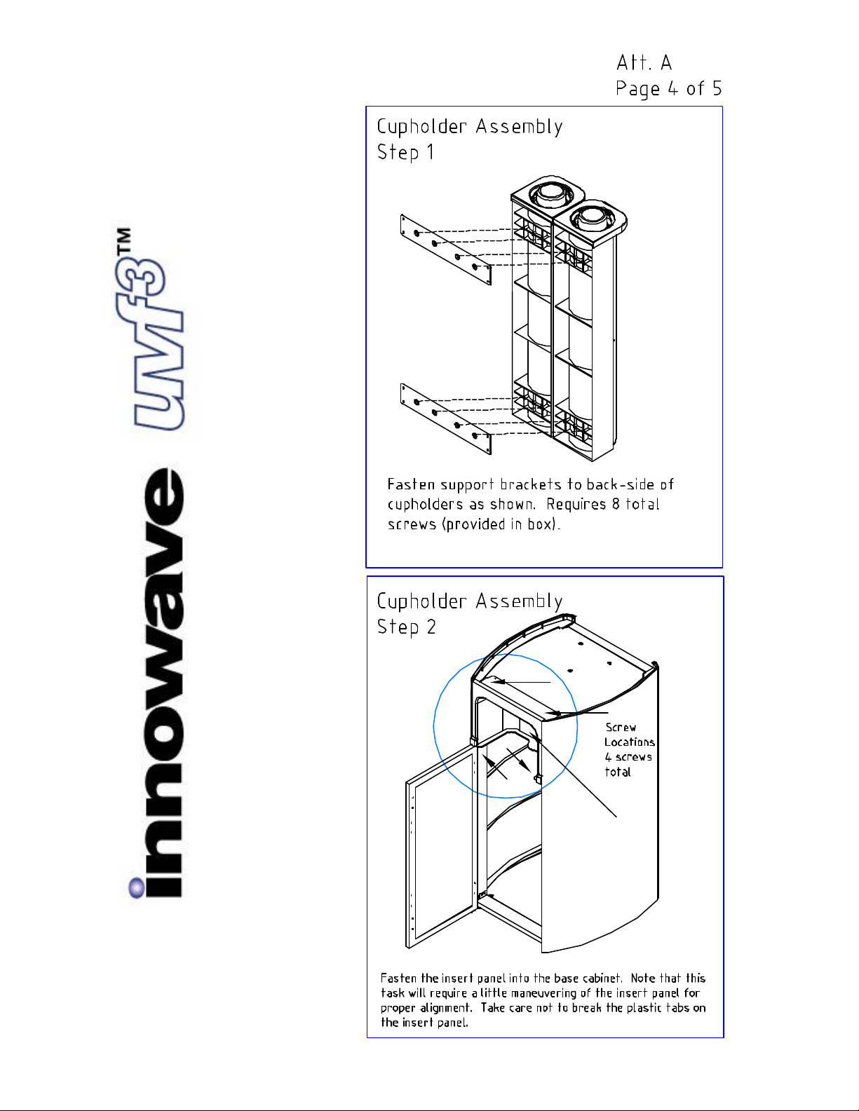
Insert Panel
Operation Manual
Rev NC
October 1, 2003
Operation Manual
Rev NC
October 1, 2003
Table of contents


