8
Maintenance
The TPR valve should not vent under normal conditions so to ensure the valve does not become inoperable, instruct the
home owner to manually open and vent every 6 months according to the maintenance section in the owner’s manual.
Rotate the red knob approximately ¼ of a turn and hold in that position for 5 seconds while hot water is vented into the
drain. This helps clear any naturally occurring lime deposits that may cause it to malfunction. If it fails to vent any
water or continues to vent water when released, immediately switch off the power and replace it.
7. Cold Water Expansion Control
Protanks require a cold water expansion valve with a maximum set point of 600kPa which must also be fitted with a drain
pipe. For convenience sake the TPR and CWE valves are vertically aligned to allow an easy connection to a common drain.
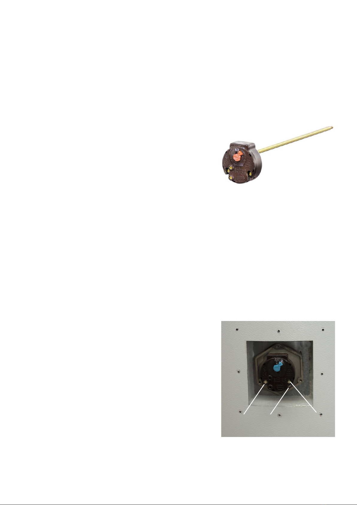
8. Thermostat Control
In accordance with G12 AS1 requirement to disinfect stored water
for legionella bacteria, the cylinder thermostat has been set to 62°C.
Thermostat settings must only be adjusted by an electrician or other
suitably qualified tradesperson. The access cover to the element and
thermostat must only be removed by an electrician or other suitably
qualified tradesperson.
Delivery Temperature
In the absence of a tempering valve the delivery temperature of water will reflect the set point of the cylinder thermostat
which could cause severe scalding. G12 AS1 prescribes the maximum permissible delivery temperature according to the
installation environment;
• 45°C for early childhood centers, schools, nursing homes or similar facilities
• 55°C for all other sanitary hot water systems
To comply with these requirements, a temperature limiting device, such as a tempering or thermostatic mixing valve is
required to ensure these limits are not exceeded.
9. Supply Pressure Control
The maximum inlet supply pressure is 500kPa and the recommended inlet supply pressure is 300kPa. 300kPa pressure
is standard practice applied in Europe to protect taps and appliances, minimise the chance of water hammer and reduce
water consumption usage. Unless certain that 500kPa cannot be exceeded (e.g. a pressure controlled pumped supply)
then a pressure limiting valve must be installed on the supply side. Failure to do so may cause damage to taps and
appliances and will unnecessarily vent and waste water which will cause
premature failure of the TPR and CWE valve.
10. Electrical Supply and Connections
The electrical connection must be carried out by a qualified person in
accordance with New Zealand Electrical Regulations. The water heater
must have the heating element connected to an independent, fused, AC
230 V 50 Hz power supply capable of withstanding the appliance load
with an isolating switch installed at the switch board.
1. The water heater must be filled with water prior to connection to the
power supply.
2. Ensure the power supply is disconnected.
3. Remove the element cover fixing screws and connect all LIVE, NEUTRAL
and EARTH wires in accordance with the wiring diagram below.
4. Ensure all wiring links are secure and protected from contact with the
internal hot surface of the water heater prior to fixing the access cover
and turning the power on.
5. To ensure the over-temperature and energy cut-out is set press the
‘reset’ button on the thermostat.
NEUTRAL EARTH LIVE


