Watex WATEX CMS-8 User manual


2
CONTENTS
INTRODUCTION ........................................................................................................................................3
REQUIREMENTS………………………………………………………………………………………….3
SPECIFICATIONS…………………………………………………………………………………………4
SYSTEM MAIN COMPONENTS…………………………………………………………………………5
OPERATION MODES……………………………………………………………………………………..7
INSTALLATION……………………………………………………………………………………………8
START UP……………………………………………………………………………………………………15
PROBLEMS AND SOLUTIONS……………………………………………………………………………17

3
INTRODUCTION
Your WATEX CMS series water softeners are precision built high quality products.
This is an effective solution for water hardness, iron, ammonium and turbidity reduction.
These units will deliver conditioned water for many years to come, when installed and operated properly. Please study this
manual carefully and understand the cautions and notes before installing. This manual should be kept for future reference. If you
have any questions regarding your water softener, contact your local dealer or WATEX.
REQUIREMENTS
Please note that the water SOFTENER is heavy and fragile; the fiberglass tank cannot stand mechanical shocks.
Any mechanical shock can affect the operation of the softener. It is not recommended to roll or turn the softener upside down.
Use a wheeled platform to move the softener. Where it is not possible, move it together with another person using your hands.
Moving by hands, it is recommended to grab the top behind the control valve housing (the place where the control valve
connects to the tank) and the bottom behind the blue fiberglass tank.
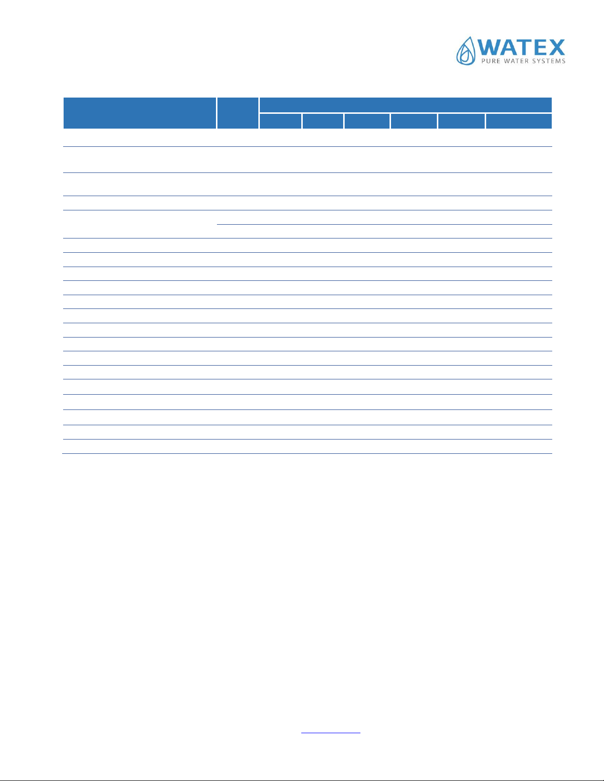
Technical requirements
Unit
WATEX Model
CMS8
CMS9
CMS10
CMS12
CMS13
CMS14
Operating water pressure
bar
2-6
Electric Connection
220V, 50Hz, 1 phase
Maximum hardness concentration
mg-ekv/l
10
10
15
20
20
20
Maximum iron concentration
mg/l
2.0
Maximum ammonium
concentration
mg/l
2.0
Water temperature
oC
2.0-36.0
•The softener should be on firm level surface.
•Mechanical filter with minimum 50 microns filtration rate is required to prolong lifetime
•If Iron is concentration is higher than 2 mg/l, iron removal filter should be installed before softener.
•DO NOT use pipe wrench to tighten nuts or caps.
•DO NOT place screwdriver in slots on caps and/or tap with a hammer.
•DO NOT install the appliance backwards. Follow arrows on inlet/outlet.
•DO NOT connect the drain and overflow (gravity drain) together.
•ALWAYS make bypass line for the softener.
•Install pressure indicators before and after the softener.
•Install after the pressure tank
4
SPECIFICATIONS
Technical parameters of
equipment
Unit
WATEX Model
CMS8
CMS9
CMS10
CMS12
CMS13
CMS14
Flow rate Qmax
m3/h
0.6
1
1.6
2.2
2.8
3.6
The amount of water for
regeneration (min)*
liters
100
130
156
200
250
300
The amount of water for
regeneration (max)
liters
189
288
428
596
743
1010
Softener Capacity ** (default set)
m3
Resin tank size (diameter)
inches
8
9
10
12
13
14
m
0.2
0.23
0.25
0.3
0.33
0.36
Resin tank volume
liters
25
32
64
85
110
145
The amount of cationic resins
liters
15
25
40
55
70
100
Brine tank volume
liters
70
70
70
70
100
100
Dimensions
Length
m
0.53
0.56
0.59
0.64
0.84
0.87
Width
m
0.28
0.28
0.28
0.3
0.46
0.46
Height
m
1.14
1.47
1.62
1.57
1.62
1.91
Weight (filled with water)
kg
50
60
70
95
155
195
Connection in-out-drain
inches
1”-1''-3/4''
1 ¼”-1 ¼”-1''
Clack control unit
WSCI 1”
WS CI 1,25''
Filtration
Hardness, iron, ammonium
Resin tank material
FRP (fiberglass)
Brine tank material
PE (Polyethilene)
Filtering material
Cationic exchange resins, silica sand 1x3mm, 3x5 mm
Power consumption
Watts
3 W
*The amount of water for regeneration depends on water hardness and iron, turbidity, ammonium concentration.
** Softener Capacity depends on water hardness and iron, turbidity, ammonium concentration and should be calculated for each
water separately to get the best results and to reduce salt consumption and water for regeneration.
Please contact to your local dealer or WATEX to program the right capacity.
Important notes:
Softener does not remove smell, organics, bacteria or viruses.


6
On the filtering tank of the filter is installed the CLACK WSCI control valve, which controls automatic regeneration of the
softener.
The control valve housing is made of plastic alloy. The control panel is located in front of the filter, and the water supply and
sewerage connections are in the rear.
The control valve is operated by voltage of 220 V. The control valve has the motherboard, which stores and regulates all the
rinse process parameters. To rinse the filter the voltage is fed from the motherboard to the built-in motor that moves a cylindrical
detail built-in the unit into a certain position.
On the left part of the control valve housing at the outlet manifold is a built-in meter that counts the quantity of water consumed.
The rinse algorithm is based on the volume of water consumed, which is counted by the built-in meter. Easy locking drain/ brine
clip for easy removal. Standard ¾” Male NPT 90° drain elbow that swivels 180° for easy orientation.
3/8” Parker Liquifit brine elbow that swivels 270° for easy orientation. Built in internal flow meter off the side of the outlet port
for easy maintenance.
2.1.2. Brine tank
The brine tank is intended for storing Sodium Chloride NaCl (salt tablets). There are several components inside brine tank: a
safety float, brine well, grid plate. Normally the water level should be about 1/3 of the brine tank height. This is sufficient to
dissolve part of the NaCl regeneration cycle.
Brine well: The brine well is a cylindrical barrier that keeps the salt or potassium chloride
away from the safety float and air check valve which allows them to operate without any
obstructions.
Brine Tank Safety Float: A safety float is included inside the brine tank to ensure that salt
water does not overflow onto the floors if the injectors on the control valve get blocked up.
Float level can be adjusted, but in normal operation it is not necessary.
Grid plate (salt platform): A grid plate is placed at the bottom of the brine tank. The grid
plate acts as a tool to displace the water. This allows more water to flow into the brine tank
to ensure that enough brine solution is available during the regeneration process.
Salt must be periodically added to the brine tank, it should be located where it is easily
accessible.
Fill salt cabinet when water level is above salt level. Do not mix different types of salt. If iron is present in your water, use a salt
with an iron-cleaning additive to help keep resin clean. You may also use a resin cleaner on a monthly basis in place of salt with
cleaning additives. If iron is not present in your water, a clean pellet, solar or cube type salt is recommended.
The use of rock salt is not recommended because it contains impurities that can plug up the injector assembly.
2.1.3. Resin tank
The filter tank is filled with ion exchange resin (cationic), which reduces hardness and iron concentration in water. Capacity of
filter material is calculated according to amount of resins and raw water quality. When capacity is exhausted, regeneration by
salt is performed.

7
OPERATION MODES
WATEX CMS softeners have two operation modes: Service and Regeneration mode.
When the softener is In Service it is flowing water through the system and removing hardness minerals from your water.
Regeneration have 5 cycles:
1. First Backwash is a rapid upward flow of water that loosens the resin bed and flushes iron particles, dirt and sediments
filtered in the bed out to the drain.
2. Brine Draw is the process in which brine is drawn out of the brine tank and passed through the resin in a downward
direction. This rinses the resin and large amounts of sodium ions replace the hardness ions accumulated during service.
3. Second backwash. After brine is completely removed from the brine tank into the resin tank the brine floating valve closes.
Water replaces any remaining brine from the resin, flushing hardness ions removed from the resin to drain.
4. Rinse is a fast flow of water down through the resin tank that follows a second Backwash. This flushes all remaining brine
from the tank and packs the resin bed for softening efficiency.
5. Fill. Brine is water saturated with large amounts of a salt (sodium chloride). During brine fill, water flows into the salt
storage area after each regeneration and dissolves salt. During the regeneration process, hardness ions on the resin beads are
replaced or exchanged for sodium ions from the brine solution.
8
INSTALLATION
General conditions
The softener must be placed on the flat, leveled surface.
It is recommended to install the softener in the technical room with sound absorbing, because during the regeneration (usually at
night), the flow of water to the sewers could be heard.
The control valve and connection fittings are not intended for supporting the weight of the water supply system.
All sanitary-technical works to be performed in accordance with local plumbing and electrical codes.
Filter must be provided with a continuous supply of water, which does not differ in quality and quality within 30% and has the
pressure range of 2.0 to 3.5 bar.
The distance between the drain and the water conditioner should be as short as possible.
The room temperature must not be lower than + 5 °C and not higher than 45 °C.
Do not use for the filter connections petroleum jelly, oils, hydrocarbon lubricants or spray silicone. Silicon grease can be used on
black o-type sealing rings, but it is not necessary.
Nuts and bolts have been designed so they can be unscrewed or tightened by hand or special plastic key. If you need to unscrew
the tightened nuts or couplings, you can use pliers. However, take care not to damage the plastic parts. Do not use wrenches or
socket wrenches to tighten or loosen.
Do not place the screwdriver into sleeve/cap openings and do not strike with a hammer!
Teflon tape is not necessary for sewer and reagent connection fittings.
Place the water filter so that the distance between the drainage outlet and the filter is minimized.
Perform a general preventive maintenance at least once a year.
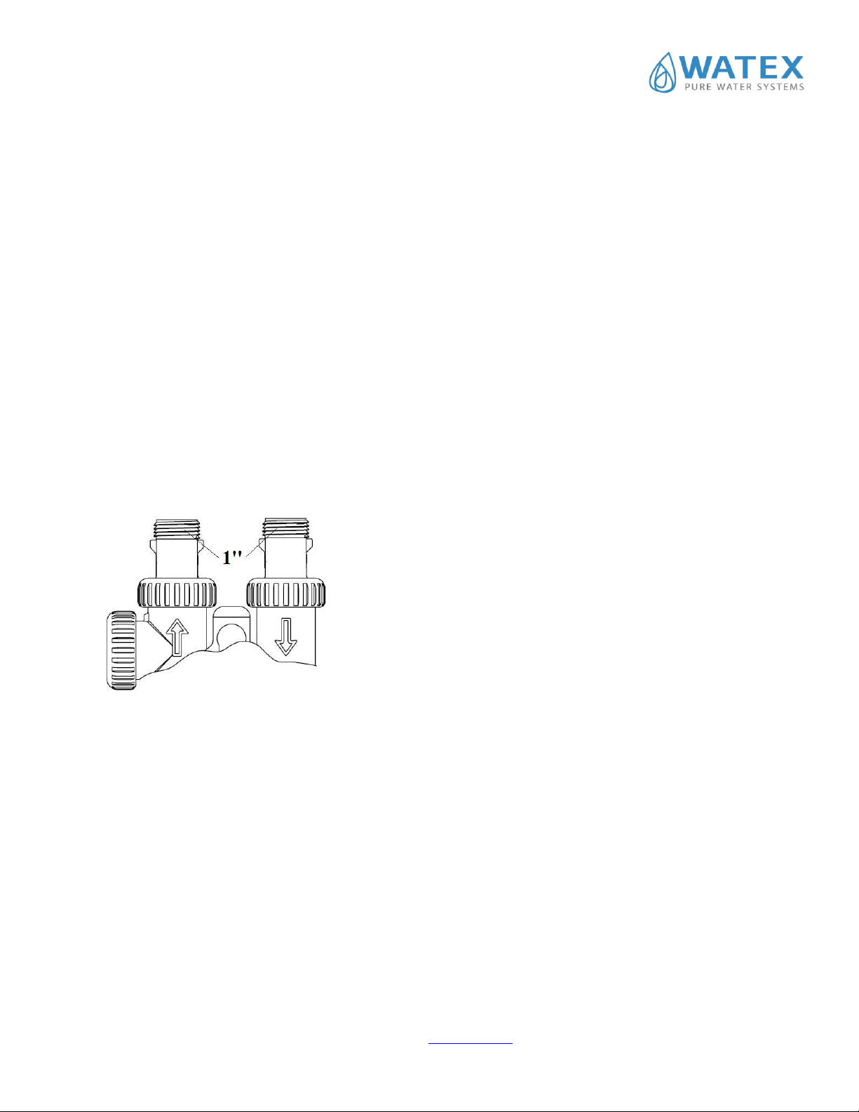
Water pipe connection In the rear of the water filter is the water supply connection. Each connection has
the inflow and outflow indicating arrows. If you look at the filter from the front, on
the right side is the inflow and on the left side is discharge. The filter’s connection
to the mains outer thread size 1 '' (inch), of both input and output. Plastic threaded
fitting is of a screw type and it can freely rotate the ring, keeping the density.
Therefore, there is no need for very powerful (sufficient hand strength) tightening
of the bolts on the control valve housing.
Use of Teflon tape on the plastic threads is a must.
The material of the piping, which connects to the filter, does not make significant
difference. Most important is that the filter does not bear the weight of the water
supply system.
Filter can be connected with the cast iron, glued, PVC screw-fastening pipes. It is
also possible with flexible metal pipes, soldered brass pipes.
Note: soldering of pipes must be carried out before connection to the control valve plastic fittings failing to follow this rule can
result in internal damage of the plastic fittings and they will not provide consistency of connection.
Soldering fittings must be cooled down. Avoid soldering grease contact with any connecting fitting parts.
For the water filter, it is recommended to install a bypass valve, as shown in the figure, and sample valves before inflow and
outflow as well.
During the normal operation, bypass valve is closed, but the input and an output valves are open.
During the preventive maintenance works on the installation or filter repair, the not purified water can be supplied to the
consumers.
It is recommended to install the sampling valve before and after the filter to compare /determine the quality of raw water and the
just- purified water. It is also advisable to install pressure gauges before and after the filter to control the pressure loss in the
installation.
In order to enhance the durability of the filter first it is recommended to install a mechanical filter that prevents sand particles,
which can be lifted out of the hole and to lead to clogging the parts of the filter.
9
Drainage connection
The filter requires to be connected to the sewer in order to ensure regular rinsing. During the rinsing time, the air bag of the filter
is removed along with the accumulated dirt (mud, iron, sand, clay, etc.).
Drainage connection points are located at the top of the control valve. We recommend using a garden hose for drainage of
rinsing water from the filter to the common sewage system.
Note: the bend of the sewer connection has the sealing ring; it is possible to turn it in the desirable direction. Turning angle is
270o.
Important: Ensure that the drainage pipe during rinsing is not dropping
out. Secure it!
Important: Make sure the garden hose is not folded, because it will reduce
rinsing water flow and the filter is likely to have incomplete rinsing, which
can lead to poor water supply.
Drainage pipe can be placed in the common sewer around 0.5 meters above
the control valve, but during the first rinses watch if the full rinsing of the
filter is really going on.
If there is no complete rinsing, consult with "WATEX" technical center.
Important: Gravity Drainage pipe shall be not less than D40.
Important: Never drive the drain hose directly into drains or the receiver.
Always allow air access between the drain hose and the tank to avoid
backflow.
Important: To prevent the sewer smell come into the filter and cause
bacteriological contamination of the filter before entering the sewage
system it is recommended to create hydro seal or siphon.

10
Reagent tank connection
The kit contains a reagent tank as well as a 3/8 "connecting pipe. The flexible plastic tube is placed in the reagent container
under the lid. The reagent tank should be placed next to the filter tank. Can be placed on any side of the filter tank.
The reagent tank has a plug that is placed in the plastic container of the reagent tank. Remove the float and remove the transport
rubber put on the bottom of the float. Threads do not have to use packaging materials.
Remember!
The regeneration tank will need to be filled with a reagent on a regular basis, so it is advisable to place it where it is easily
reachable.
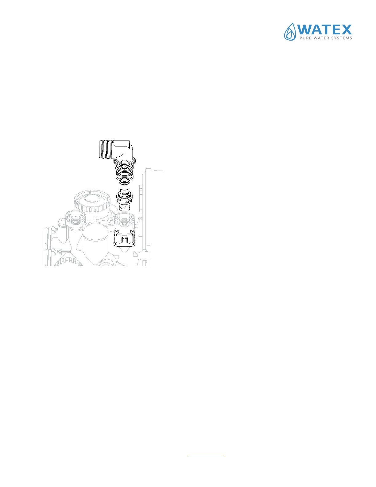
The control panel is shown in the drawing, highlighting the connection point of the reagent supply line. The pipeline connection
is carried out as follows: 1.Unlock the control unit reagent by removing the
clamp and removing the reagent attachment elbow.
2. Pull the pipe through the nut
3. Place the cylindrical insert on the end of the tube,
then make two consecutive rings.
4. Insert the end of the tube into the bend hole to the
end and tighten with the nut. Manual engagement.
5. Place the reagent joint in the opening and place the
clamp.
Note: The reagent connection elbow has a sealing
ring, it can be rotated in the desired direction.
Turning angle is 270o.
6. The end of the second tube is drawn through the
hole in the side of the reagent tank and added in the
same manner as in paragraphs 2, 3 and 4.
When the equipment is connected to the water
supply, drainage and reagent tanks, in the reagent
container, fill salt tablets (NaCl) in Brine tank.

11
Bypass (option)
•Directional shut-off arrows for flow: Normal, Bypass, Diagnostic mode, Shut-off mode.
•Radial seals allow side-to-side and up/down minor plumbing misalignments, connections need only hand tightening.
•One internally lubricated O-ring on rotor creates less friction.
Bypass Valve Operation
12
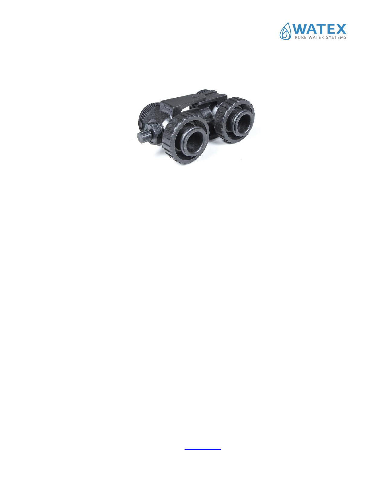
External In-Line Mixing valve (option)
You can use the external in-line mixing valve on water softeners to blend a desired amount of hardness back in the line or use it
on a carbon filter to blend a small amount of chlorine back in the line.
Electrical connections
The softener is supplied with electricity transformer (AC adapter), which operates at 220 V. Power supply to the softener must
be continuous. AC adapter is designed for dry places only.
Note: All electrical connections must comply with local regulations.
To ensure a continuous supply of electricity from the source located not farther than 2 meters from the water softener.
Adapter wire must be connected inside the control valve.
1. Remove the front cover of the control valve.
2. At the top of release the middle mounting tab that keeps the motherboard frame to the control valve.
3. On the right side of the plastic wall of the control valve there is a hole through which to pull the transformer’s
(adapter’s) tip.
4. The tip to be connected to the contact terminals at the right lower part of the motherboard.
5. The rest of the cable should be placed along side the frame of the motherboard behind the specially designed clamps.
6. Push back the motherboard-mounting frame to fastening tab and secure it in the original position.
7. Install the front button cover.
13
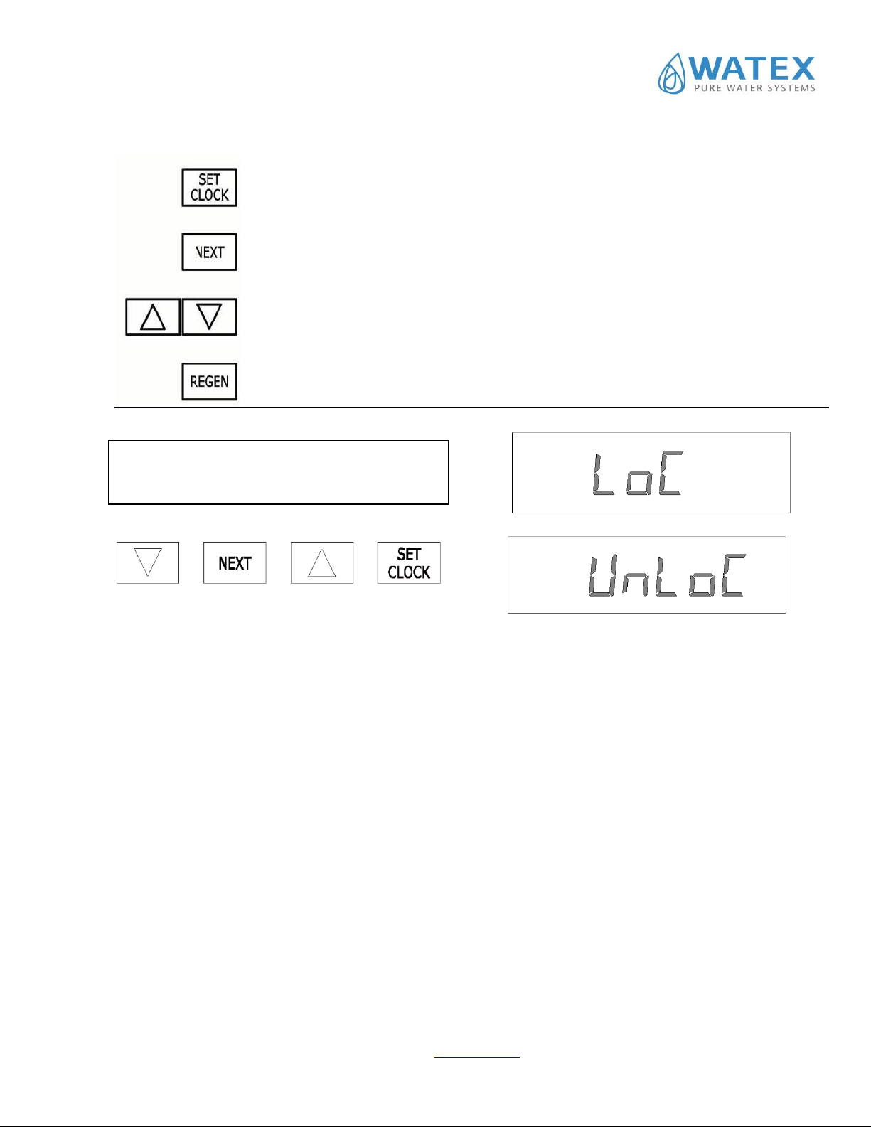
Button Operation and Functions
Setting Time of Day
Setting Time of Day
Allows programmer to set the time of day or to “Escape” out of
programming and save any changes made while in programming modes
Toggles between available User Display Screens or
Allows programmer to advance to the next display screen in programming mode
Change variable being displayed in programming mode
Toggles scheduled regen on/off
Hold for more than 3 seconds to start immediate regen
Backs up 1 step in programming mode
By pressing the above buttons in order you can
Lock (LoC) or to Unlock (UnLoC) someone from
accessing the OEM setup screens


15
START UP
Usually all key operating parameters of the WATEX CMS series filter have already been set at the service center. The only thing
that is planned to set for the first run is the time setting.
Regeneration cycles and capacity programming
Press and hold the “NEXT” button simultaneously and arrow down and hold for 3 seconds.
1) The word "softening" flashes in the upper left corner.
2) Press "NEXT". The first "backwash" and the duration of the cycle appear in minutes. Arrows and is possible to
change the duration of the cycle.
3) Press "NEXT" and the second mode "brine" (brine suction) and cycle duration in minutes are displayed. With arrows
and it is possible to change the duration of the cycle.
4) Press "NEXT". The second "backwash" and the duration of the cycle appear in minutes. Arrows and is
possible to change the duration of the cycle.
5) Press "NEXT" ."rinse" and the duration of the cycle appear in minutes. Arrows and it is possible to change
the duration of the cycle.
6) Press "NEXT" and "fill" (reagent tank refill) and mode duration in minutes are displayed. Arrows and it is
possible to change the duration of the mode.
7) Press "NEXT" to display the capacity of the unit in cubic meters. Use the arrows to change the capacity of the
machine. By pressing "NEXT" the previously set data is automatically saved and the programming progresses to the
next settings. Next, press "NEXT" until the current day is displayed.
Therefore, the setup cycle is closed and all settings are saved.
Rinsing mode duration and volume settings
In some circumstances, there is a need to change the rinse mode duration. To do this, do the following:
Press and hold simultaneously the button “NEXT”and the arrow down for 3 seconds.
1) In the upper left corner flashes the word "filtering".
2) Press “NEXT” and there will appear the first rinsing mode “backwash’’ and duration of the mode in minutes. Duration
of the mode can be changed by arrows and .
3) Press “NEXT” and there will appear the second rinsing mode “brine’’(agent suction in) and duration of the mode in
minutes. Duration of the mode can be changed by arrows and . Press “NEXT”.
Thus, the setting mode is closed and all the settings are saved.
Manual regeneration
Sometimes you need to make regeneration earlier before the system determines that it is necessary; it is usually referred to
as manual regeneration. It is possible that there was a period when the water has been used more than usual, for example, where
there have been more visitors or more linen have been washed.
To initiate a manual regeneration in the set deferred regeneration time press and release REGEN. Then the display will flash
the words "REGEN TODAY", indicating that the system will initiate regeneration before the pre-set regeneration. If you have
pressed the "REGEN" button by mistake, re-pressing the button will cancel the request.

16
To immediately start the manual regeneration, press and hold the "REGEN" button for 3 seconds. The system will
immediately begin regeneration. This command cannot be canceled.
When the system starts regeneration, the display will change showing information on the recovery process steps and the
remaining time up to the end of the regeneration step. The system will automatically pass through recovery steps and when the
regeneration is complete, set itself in the water treatment mode.
Operation control
During operation, the normal user display is:
•time of day;
•current flow rate liters per minute
•remaining capacity cubic meters per hour.
Each of these can be viewed by pressing NEXT to scroll through them. When stepping through any programming, if there aren’t
any buttons pressed within 5 minutes, the display returns to a normal user display. Any changes made prior to the 5 minute time
out are incorporated.
To quickly exit any Programming, Installer Settings, and so on, press SET CLOCK. Any changes made prior to the exit are
incorporated.
If desired, regeneration at preset time (default 2:00), press the REGEN button. REGEN TODAY will appear on screen.
If desired, immediate regeneration, press and hold the REGEN button for five seconds until a regeneration begins.

17
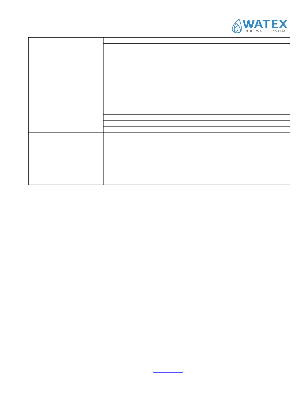
PROBLEMS AND SOLUTIONS
Problem
Possible cause
Solution
1. The timer does not display time
a. transformer not connected
a. reconnect
b. No voltage in electrical outlet
b. Repair the outlet or use a working outlet
c. transformer failure
c. Replace transformer
d. Electronic plate damaged
d. Replace electronic plate
2. The timer does not display the
correct time
a. Connection jack disconnected
a. Try another jack
b. power failure
b. Re-set time
c. Electronic plate damaged
c. Replace electronic plate
3. It does not display ''softening",
when the water is flowing
a. Water flows through the bypass
and not through the filter
a. switch the bypass
b. meter disconnected
b. reconnect the meter to the electronic board
c. Meter turbine jammed / stopped
c. Remove the meter and check if there is some
foreign material
d. meter damaged
d. Replace meter
e. Electronic plate damaged
e. Replace electronic board
4. Control valve starts
regeneration at wrong time
a. There has been a power outage
a. set the correct time in the control valve.
b. the time set not correctly
b. set the time correctly
c. wrong regeneration time
c. re set regeneration time
d. Control valve set for immediate
regeneration
d. Check the control valve setting of recovery time
options.
5. An error with the code number
1001 or E1 –It is not possible
to identify the start of
regeneration
1002 or E2 –unexpected stop
1003 or E3 –Motor runs too long,
out of adjustment trying to reach
the next regeneration cycle
position
1004 –Motor runs too long, out
of adjustment, trying to reach the
starting position
If some other code shows up,
contact the manufacturer.
a. Control valve has just been
served
a. for 3 seconds Press NEXT and REGEN or pull-
out wire (black) from the power supply and
reinsert to set the control valve
b. control valve jammed
b. Check piston and spacer block if they are not
stuck
c. High drive forces on the piston
c. Replace piston and spacer block components
d. control valve plunger is not in
home position
d. for 3 seconds Press NEXT and REGEN or pull-
out wire (black) from the power supply and
reinsert to set the control valve
e. motor is not fully inserted in
order to achieve the drive gears,
motor wires damaged or
disconnected, motor failure
e. Check motor and wires. Replace motor if
necessary
f. The drive label damaged or dirty,
the mechanism is missing or
damaged
f. Replace or clean the drive mechanism.
g. The drive base inserted into plate
incorrectly
g. Thoroughly check the drive bracket
h. Electronic plate is damaged or
defective
h. Replace electronic plate
i. Electronic plate is incorrectly
connected to the base of the drive
i. Make sure that the electronic circuit board is
properly connected to the drive bracket.
6. Control valve stopped during
regeneration
a. Motor does not run
a. Replace motor
b. No voltage in the socket
b. repair the socket or use working socket
c. adapter (transformer) damaged
c. Replace transformer
d. electronic plate damaged
d. Replace electronic plate
e. Faulty actuator or drive cover
part
e. Replace actuator or drive cover part
18
f. damaged piston holder
f. Replace piston holder
g. Defective main piston or
recovery piston
g. Replace main piston or recovery piston
7. Control valve does not make
recovery automatically when the
REGEN button is pressed and
held
a. transformer is unplugged from
contact
a. reconnect transformer
b. No voltage in the socket
b. repair the socket or use working socket
c. Faulty actuator or drive cover
part
c. Replace actuator or drive cover part
d. Electronic plate damaged
d. Replace electronic plate
8. Control valve does not make
recovery automatically, but it does
so when REGEN button is pressed
a. Water flowing through the bypass
a. Close the bypass.
b. the meter is disconnected
b. Connect the meter to the electronic board
c. Meter turbine jammed / stopped
c. Remove the meter and check if there is some
foreign material
d. meter damaged
d. Replace meter
e. Electronic plate damaged
e. Replace electronic plate
f. error in settings
f. check control valve settings
9. Time flashes: appears and
disappears
Electricity supply break has been
longer than 2 hours, the transformer
has been unplugged from the outlet
and then plugged in again, the
transformer plug has been taken out
and then re-connected to the plate
or the NEXT and REGEN buttons
have been pressed to re-reset
control valve.
a. Re-set the time
This manual suits for next models
5
Table of contents


