WATSON INDUSTRIES ARS-G152 User manual

Watson Industries, Inc. ARS-G152 Rev A 05/02/2019
1
Angular Rate Sensor
Owner’s Manual
PART NUMBER: ARS-G152
WATSON INDUSTRIES, INC.
3035 MELBY STREET
EAU CLAIRE, WI 54703
Phone: (715) 839-0628
Fax: (715) 839-8248
Email: support@watson-gyro.com

Watson Industries, Inc. ARS-G152 Rev A 05/02/2019
2
Table of Contents
Introduction................................................................................................................... 3
Product Description...................................................................................................... 3
Installation .................................................................................................................... 3
Orientation .....................................................................................................................................................................3
Mounting........................................................................................................................................................................3
Environment: .................................................................................................................................................................3
Power.............................................................................................................................................................................3
Calibration .....................................................................................................................................................................4
Operation ...................................................................................................................... 4
Initialization...................................................................................................................................................................4
Interface.........................................................................................................................................................................4
RS-232 Output Format...............................................................................................................................................4
RS-232 Input Commands...........................................................................................................................................5
Analog Outputs..........................................................................................................................................................7
Built in Test Digital Output .......................................................................................................................................7
Specifications................................................................................................................ 8
Connections .................................................................................................................. 9
Dimensions ................................................................................................................... 9
WARNING................................................................................................................. 10
DISCLAIMER
............................................................................................................... 10
WARRANTY
................................................................................................................. 10
PRODUCT LIFE
............................................................................................................ 10
Appendix B................................................................................................................. 14
Activating Command Mode (Double Spacebar Mode)................................................................................................14
Accessing the Main Menu............................................................................................................................................14
Appendix B.1 Set Output Channels.............................................................................................................................14
Appendix B.2 List Output Channels............................................................................................................................15
Appendix B.3 Set Analog Voltage Range....................................................................................................................15
Appendix B.4 Set Output Bandwidth...........................................................................................................................16
Appendix B.5 Set Binary Output Format.....................................................................................................................16
Appendix B.6 Set Baud Rate .......................................................................................................................................17
Appendix C Binary Output Format............................................................................ 18
Appendix C.1 Two Byte Binary Data Format..............................................................................................................18
Appendix C.2 Three Byte Binary Data Format............................................................................................................20
Watson Industries prides itself on solving customer problems and serving their needs in a timely fashion. This manual
is intended to facilitate this goal and to provide written information about your product. We ask that you carefully read
this manual. Becoming familiar with the manual will help you understand the product’s capabilities and limitations, as
well as provide you with a basic understanding of its operation. If, after reading the manual, you require further
assistance, do not hesitate to call Watson Industries with your questions and comments.
CAUTION!
Watson Sensors are rugged devices that have been used successfully in a number of harsh
environments. The components have been qualified to withstand a mechanical shock of 500g 's or
greater, and most enclosures provide near that level of protection. However, dropping a sensor
from waist height onto a hard floor can cause a shock level of 600g's. At this level, given some
resonance, damage is possible.

Watson Industries, Inc. ARS-G152 Rev A 05/02/2019
3
Introduction
The Watson Industries Angular Rate Gyro represents a significant advancement in inertial sensor
technology. It is a highly accurate and rugged device with many advantages over other types of
angular rate devices. This manual describes operation of the Watson Industries ARS and also
provides useful application information to the system designer.
Product Description
The Watson Industries angular rate gyro is a solid state, single axis angular rate sensor. The gyro
provides a voltage proportional to the rate of turn about its sensitive axis. During rotation, positive
voltage output occurs in the direction of the rotational arrow indicated in figure 2. There are four
analog outputs available (400°/s , 200°/s , 100°/s , 50°/s fullscale). The analog outputs are user
selectable between unipolar (0-5 VDC) or bipolar (±5 VDC). The bandwidth is also user
adjustable from 5 to 200 Hz. A power supply, providing +8 to +45 Volts DC, is required to operate
the unit.
Installation
Orientation
The base of the unit is to be mounted on top of a horizontal surface. The gyro drawing, with pinout,
is located in figure 2. The gyro is a rugged device and will withstand harsh environments.
However, due attention needs to be paid to the nature of the sensor and its prime function, which is
to measure angular rate.
Mounting
The unit has three 0.12” diameter mounting holes for using three # 4 (or 3 mm) screws. To
avoid distortion, the unit must be attached to a clean, flat surface, and the fasteners must be
tightened evenly.
Environment:
Avoid mounting sites that are subject to significant temperature variation over the duration of the
test. Temperature variation will induce significant rate sensor bias drift, which will reflect in poor
angular rate accuracy.
For all applications, it is preferable to install the device where linear dynamic effects are
minimized.
Power
This unit has an internal regulator to allow operation over a wide voltage input range. Best
operation is obtained at either +12 or +24 VDC level, although operation is fully satisfactory down
to +8 VDC and up to +45 VDC. The power ground is already connected internally to the signal
ground. Do not connect the ground wires externally.
Power consumption of the unit is about
0.7W. Internal capacitors are provided to remove a reasonable level of power line noise, however,
capacitors should be added for long power line wiring or if noise is induced from other loads on the
circuit.

Watson Industries, Inc. ARS-G152 Rev A 05/02/2019
4
Calibration
The ARS is calibrated at the factory before it is shipped to the user. It is recommended that the
unit be examined, preferably at the factory annually for evaluation and recalibration.
Operation
Initialization
The initialization time typically takes 4 to 5 seconds. During this time, a message is sent from the
unit via the RS-232 serial link. This message gives information about the Gyro such as the full
model number, serial number, and firmware revision. The message can be read by using a terminal
program or by using the terminal mode of Watson Industries’ communication software.
Interface
RS-232 Output Format
The standard RS-232 output is received from the 12-pin connector. The digital output pin map can
be found in the Connections section of this manual. The RS-232 output consists of a string of
decimal ASCII characters sent asynchronously at regular intervals. By default, the string is sent at
9600 baud with eight data bits, one stop bit and no parity. The RS-232 signal is referenced to signal
ground. The number of strings sent per second depends on the baud rate and the output format. The
maximum rate is 250 strings per second. The contents of a typical string are formed as follows:
(See Appendix B for information on how to change the data string.)
1. A single letter and a space used to indicate the start of the data string. The letter “I”
indicates the start of an inertial data string.
2. A eight character string representing the angular rate starting with a space, then a “+” or a
“-“, followed by three digits, a decimal point and two digits for up to ±399.99 °/second.
3. The string is terminated by a carriage return. There will then be a short interval with no
data transmission before the next string begins.
Example:
I
+002.05
<CR>
(1)
Angular
Rate
(2)
space space
The data items transmitted can be changed by using the menu system (see Appendix B). More
channels are available for output (see Appendix A).
The system is protected from inadvertent write-over of the EEPROM by requiring two spacebar
commands during the initialization interval to access the EEPROM or related functions.
The baud rate may be changed from the nominal value of 9600 baud by modifying the default
value in the EEPROM of the unit to 38.4K, 19.2K, or 4800 baud.

Watson Industries, Inc. ARS-G152 Rev A 05/02/2019
5
A text header that is sent by the Gyro during initialization identifies the unit by part number and by
serial number and gives the date of last calibration. Additionally, a line of text characters that
identifies the data channel columns is sent if the serial output is set to ASCII decimal. This whole
message can be temporarily (or as a default) suppressed or restored by a “*” command from the
interfacing computer.
Data transmission sent by the ADS can also be suppressed or restored by a “+” command from the
interfacing computer. This command is typically used when only analog data is used as a noise
reduction measure.
The other output format available is a binary format. The binary format provides generally the
same information as the decimal ASCII format, but in a compact binary file message. In this
format, there are nominally 3 bytes sent that represent 1 twenty-one bit gyro output followed by a
carriage return. This format is for highly experienced users only. See Appendix C for more
information. Consult the factory for further details.
RS-232 Input Commands
The RS-232 input commands are provided for the purpose of unit test and installation set-up. Use
the same parameters that are used for the output (9600 baud ASCII nominal, or as reset in the units
EEPROM).
Note: Many commands require command or “Double spacebar mode” in order to access them. For
more information on how to activate Command Mode, see the instructions in Appendix B.
These commands are available to the user (others are used at the factory for alignment and
calibration):
1. An “!” will reinitialize the unit. Further, access to initialization is inhibited such that a
spacebar command must be sent within about 2 seconds of the “!” command for
initialization to be engaged. Command mode is not required to access this function.
2. A “Z” or “z” will reset the timer channel counter. The timer channel counts seconds since
the last reset. This command sets the timer back to zero. Command mode is not required to
access this function.
3. A “L” or “l” will transmit a line of labels corresponding to the data channels that are
currently selected for output. See Appendix A for information about the data channels and
their labels. Command mode is required for access to this command.
4. An “_” command will change the output format to decimal ASCII. This change is made
non-volatile in the unit on EEPROM by keying in the quote (“) character. Command mode
is required for access to this command.
5. A “^” command will change the output format to binary. This change is made non-volatile
in the unit on EEPROM by keying in the quote (“) character. Command mode is required
for access to this command.
6. A “:” command will toggle the output to send a frame of data upon receiving any non-
command character (On to Off; Off to On). This change is made non-volatile in the unit on

Watson Industries, Inc. ARS-G152 Rev A 05/02/2019
6
EEPROM by keying in the quote (“) character. Command mode is required for access to
this command.
Note: To test if this command is active when the unit is not flowing data, send a carriage
return (or any other non-command character to the sensor, and observe if there is any
output.
7. A “+” command will suppress or restore the transmission of data. This command will
toggle the data transmission (On to Off; Off to On). Command mode is required for access
to this command.
Note: It is possible for both the “:” and the “+” commands to be active at the same time.
The “+” command determines whether the sensor is allowed to transmit data. So if this were
the case, the “:” command must also be turned off to allow the free flow of data.
8. An “*” command will suppress or restore the initialization message in the Decimal ASCII
mode. This command will toggle the transmitting of the text header during initialization
(On to Off; Off to On). This change is made non-volatile in the unit on EEPROM by keying
in the quote (“) character. Command mode is required for access to this command.
9. An “&” command brings up a menu which allows any of several parameters to be set.
These are system time constants, selection of data channels for serial output, and baud rates.
This change is made non-volatile in the unit on EEPROM by keying in the quote (“)
character. Command mode is required for access to this command.
The commands “~”, “@”, “#”, “$”, ‘(“, “)”, “{“, “}”, “|”, “<”, “>” and “?” are used by the Watson
factory to calibrate the unit and should be used only with the assistance of the factory. If an
undesired function is called, a “Q”, and sometimes Escape or a Delete will interrupt the command
and return to operation with the least disturbance to the system. All other unspecified characters
such as carriage return, line feed and space are ignored by the system.
If there are problems with the system “hanging up” during the binary output mode, check for
crosstalk between the serial transmit and receive line in your installation. In addition, check to see
that the communications program used is not sending an echo. This will not happen in the decimal
or hexadecimal modes because command characters recognized by the system are not produced in
those modes.

Watson Industries, Inc. ARS-G152 Rev A 05/02/2019
7
Analog Outputs
Analog signal is output from a 14 bit digital to analog converter through an operational amplifier.
Each analog output has a 300 ohm resistor in series to eliminate oscillations from high capacitance
loads. The output range for the analog output channels are user selectable between unipolar (0-5
VDC) or bipolar (±5 VDC). See Appendix B for information on selecting unipolar or bipolar
output. The analog outputs are referenced to the common signal ground Pin 8. The analog outputs
can be found on the 12-pin connector. The outputs include:
Bipolar Output (±5VDC) Unipolar Output (0 to 5 VDC)
Signal Pin Range Zero Rate (0°/s) Scale Factor Zero Rate (0°/s) Scale Factor
Angular Rate 1 10 ±400°/s 0 VDC 80°/s/V 2.5 VDC 160°/s/V
Angular Rate 2 3 ±200°/s 0 VDC 40°/s/V 2.5 VDC 80°/s/V
Angular Rate 3 9 ±100°/s 0 VDC 20°/s/V 2.5 VDC 40°/s/V
Angular Rate 4 2 ±50°/s 0 VDC 10°/s/V 2.5 VDC 20°/s/V
Built in Test Digital Output
Built-In Test is an active low digital output that continuously monitors the internal sensors for
faults. This signal is available on pin 5 of the connector. This output is High (5VDC) when the unit
is operating normally. This output is Low (ground) when a fault is indicated. Flag reset is normal
operation. The fault condition is set if the Angular Rate sensor has failed or the sensors temperature
range has been extended.

Watson Industries, Inc. ARS-G152 Rev A 05/02/2019
8
Specifications
Angular Rate
Ranges: ±50°/sec ±100°/sec ±200°/sec ±400°/sec
Resolution: 0.006°/sec 0.012°/sec 0.024°/sec 0.05°/sec
Analog Scale Factor: Bipolar 100mV/°/sec 50mV/°/sec 25mV/°/sec 12.5mV/°/sec
Unipolar 50mV/°/sec 25mV/°/sec 12.5mV/°/sec 6.25mV/°/sec
Scale Factor Accuracy: 0.2% At constant room temperature
Scale Factor Temp Coefficient: 0.1% Over temperature range
Bias: ±0.1°/sec At room temp
Bias: Over Temp Range ±0.2°/sec
Warmup Drift: ±0.25°/sec
Non-Linearity: < 0.15% Full scale range
Bandwidth: 70 Hz (Typical) User selectable 5 to 200 Hz
Noise: < 0.05°/sec rms 1 Hz to 100 Hz
Environmental
Temperature: Operating -40°C to +85°C
Temperature: Storage -55°C to +85°C
Vibration: Operating 5g rms 20 Hz to 2 KHz
Vibration: Survival 10g rms 20 Hz to 2 KHz
Shock: Survival 500g 10mS ½ sine wave
Electrical
Frame Rate: 800 Hz Maximum
Startup Time: Data 5 sec
Startup Time: Fully operational 10 sec
Input Power: 8 to 45VDC 0.7W
Input Current: 45mA @ 12VDC 20mA @ 24VDC
Digital Output: RS-232
±399.99 Range
Analog Output: User Selectable ±5VDC Bipolar ; 0-5VDC Unipolar
Analog Output Impedance: 300 Ohm Per line
Physical
Size: Including Mounting Flanges 1.2"W x 2.8"L x 1.35"H 3.0 x 7.1 x 3.0 (cm)
Weight: 2.1 oz 60 grams
Connection:
Amp 4-794627-2 (12 pin)
• Specifications are subject to change without notice.
• This product may be subject to export restrictions. Export Classification ECCN 7A994
Watson Industries, Inc. ARS-G152 Rev A 05/02/2019
9
www.watson-gyro.com
WATSONINDUSTRIES,INC.
Pwr.
P/N
S/F
Rev
MADEINU.S.A
Connections
123456
789101112
The RS-232 serial and analog output connections are referenced to Signal Ground on pin 8. The
power ground is already connected internally to the signal ground.
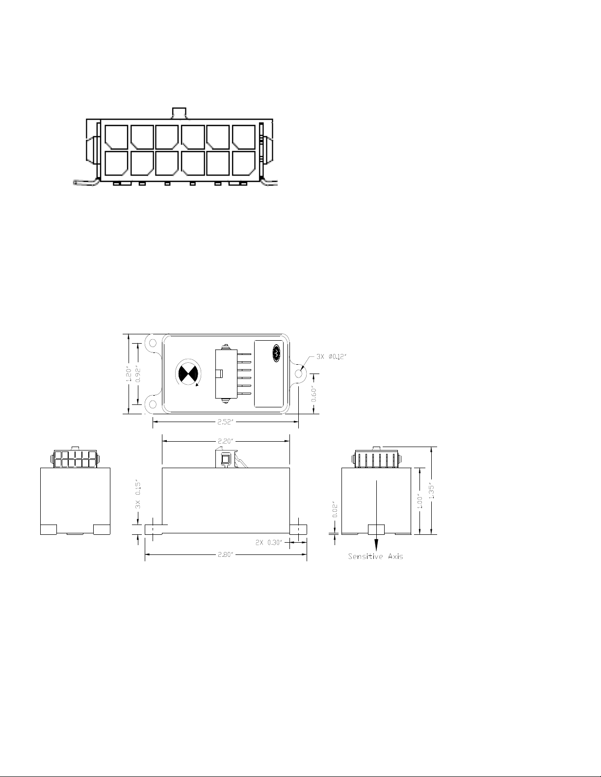
Dimensions
Figure 2
12 Pin Connector
Pin Description
1 RS-232 TXD
2 Angular Rate Analog Output 4 (±50°/sec range)
3 Angular Rate Analog Output 2 (±200°/sec range)
4 No Connection
5 Built in Test (BIT) Output
6 Power Ground
7 RS-232 RXD
8 Signal Ground
9 Angular Rate Analog Output 3 (±100°/sec range)
10 Angular Rate Analog Output 1 (±400°/sec range)
11 Factory use (Do not Connect)
12 +Vin Power +8 to +45 VDC)

Watson Industries, Inc. ARS-G152 Rev A 05/02/2019
10
WARNING
Rough handling or dropping of this unit is likely to cause damage.
Over-voltage and/or miswiring of this unit will cause damage.
This unit should be protected against prolonged exposure to high
humidity and/or salt air environments.
DISCLAIMER
The information contained in this manual is believed to be accurate and reliable; however, it is the
user’s responsibility to test and to determine whether a Watson Industries’ product is suitable for a
particular use.
Suggestion of uses should not be taken as inducements to infringe upon any patents.
WARRANTY
Watson Industries, Inc. warrants, to the original purchaser, this product to be free from defective
material or workmanship for a period of two full years from the date of purchase. Watson
Industries’ liability under this warranty is limited to repairing or replacing, at Watson Industries’
sole discretion, the defective product when returned to the factory, shipping charges prepaid, within
one full year from the date of purchase. The warranty described in this paragraph shall be in lieu of
any other warranty, express or implied, including but not limited to any implied warranty of
merchantability or fitness for a particular purpose.
Excluded from any warranty given by Watson Industries are products that have been subject to
abuse, misuse, damage or accident; that have been connected, installed or adjusted contrary to the
instructions furnished by seller; or that have been repaired by persons not authorized by Watson
Industries.
Watson Industries reserves the right to discontinue models, to change specifications, price or
design of this product at any time without notice and without incurring any obligation whatsoever.
The purchaser agrees to assume all liabilities for any damages and/or bodily injury that may result
from the use, or misuse, of this product by the purchaser, his employees or agents. The purchaser
further agrees that seller shall not be liable in any way for consequential damages resulting from
the use of this product.
No agent or representative of Watson Industries is authorized to assume, and Watson Industries
will not be bound by any other obligation or representation made in connection with the sale and/or
purchase of this product.
PRODUCT LIFE
The maximum expected life of this product is 20 years from the date of purchase. Watson
Industries, Inc. recommends the replacement of any product that has exceeded the product life
expectation.

Watson Industries, Inc. ARS-G152 Rev A 05/02/2019
11
Customer Service
All repairs, calibrations and upgrades are performed at the factory. Before returning any product,
please contact Watson Industries to obtain a Returned Material Authorization number (RMA).
Return Address & Contact Information
Watson Industries, Inc.
3035 Melby Street
Eau Claire, WI 54703
ATTN: Service Department
Telephone: (715) 839-0628 Fax: (715) 839-8248 email: support@watson-gyro.com
Returning the Product
Product shall be packaged making sure there is adequate packing around all sides. Correspondence shall
include:
• Customer’s Name and Address
• Contact Information
• Equipment Model Number
• Equipment Serial Number
• Description of Fault
It is the customer’s responsibility to pay all shipping charges from customer to Watson
Industries, including import and transportation charges.

Watson Industries, Inc. ARS-G152 Rev A 05/02/2019
12
Appendix A
The following outputs are available via the RS-232 serial link. Their full-scale ranges are listed for both decimal and
binary format.
Inertial Output Label Full Scale Decimal Full Scale Binary
Time Since Reset TM 65535 16383
Angular Rate XR ±399.99 º/s ±400 º/s
Temperature TP -40º to 88ºC -40º to 88ºC (7 bit)
Flag Bits FL 3 ASCII chars representing Octal
digits 1 byte
Status Bits ST 3 ASCII chars representing Octal
digits 1 byte
Built In Test (BIT) Status Bits BT 3 ASCII chars representing Octal
digits 1 byte
The Flag Bits contain the following information:
Bit Description (If Set)
0 Unused
1 Unused
2 Unit Temp Out of Range Flag
3 BIT Test Flag
4 Angular Rate Out of Range Flag
5 Unused
6 Checksum Error Flag
7 Unused
Example: The Flag channel output in ASCII Decimal is “020”
Octal Digit 0 2 0
Binary Equivalent 0 0 0 1 0 0 0 0
Flag Bit # 7 6 5 4 3 2 1 0
This translates into the information below:
Bit 7 Reset
Bit 6 Reset No Checksum Error
Bit 5 Reset
Bit 4 Set Angular Rate Out Range (>400 º/s)
Bit 3 Reset No BIT Error
Bit 2 Reset Unit Temp in Range (-40º to +85º C)
Bit 1 Reset
Bit 0 Reset
The Status Bits contain the following information:
Bit Description
0 Unused
1 Unused
2 Unused
3 Unused
4 If set, Unit is in Initialization
5 Unused
6 If set, Command Mode is Selected
7 Unused
Example: The Status channel output in ASCII Decimal is “120
Octal Digit 1 2 0
Binary Equivalent 0 1 0 1 0 0 0 0
Status Bit # 7 6 5 4 3 2 1 0

Watson Industries, Inc. ARS-G152 Rev A 05/02/2019
13
This translates into the information below:
Bit 7 Reset
Bit 6 Set Command mode active
Bit 5 Reset
Bit 4 Set In Initialization
Bit 3 Reset
Bit 2 Reset
Bit 1 Reset
Bit 0 Reset
The Built In Test (BIT) Status Bits contain the following information:
Bit Description
0 Unused
1 Unused
2 Unused
3 If set, Sensor Temperature out of range
4 If set, Angular Rate Sensor Failure
5 Unused
6 Unused
7 Unused
Example: The BIT Test channel output in ASCII Decimal is “020”
Octal Digit 0 2 0
Binary Equivalent 0 0 0 1 0 0 0 0
BIT Status Bit # 7 6 5 4 3 2 1 0
This translates into the information below:
Bit 7 Reset
Bit 6 Reset
Bit 5 Set
Bit 4 Set Rate Sensor Failure
Bit 3 Reset Temp Sensor in range
Bit 2 Reset
Bit 1 Reset
Bit 0 Reset

Watson Industries, Inc. ARS-G152 Rev A 05/02/2019
14
TYPE IN THE NUMBER OF YOUR SELECTION (OR 'Q' TO QUIT):
1 = SET OUTPUT CHANNELS
2 = LIST CURRENT OUTPUT CHANNEL SELECTION
3 = SET ANALOG VOLTAGE RANGE
4 = SET OUTPUT BANDWIDTH
5 = SET BINARY OUTPUT FORMAT
6 = SET NEW BAUD RATE
Appendix B
Activating Command Mode (Double Spacebar Mode)
1) Connect the unit to a DC power source that is off.
2) The viewing computer needs a valid bi-directional RS-232 serial port. Connect the serial
port of the Watson sensor to the computer’s serial port.
3) Open a terminal program (such as HyperTerminal) to interface with the unit. The default
baud rate of the unit is 9600 baud. Make sure the computer’s serial port is open.
4) Power-on the unit. A startup message will be transmitted by the unit and will appear in the
terminal window unless it has been suppressed (See RS-232 Input Commands above).
5) During initialization, hit the space bar twice within close succession.
Note: The sensor initialization time begins after the startup message is transmitted.
Typically, this time period lasts 5 seconds, but could be as long as 127 seconds depending
on your sensor.
6) Wait until after initialization is finished. At this point, command mode will be activated and
the unit will accept keyboard commands.
Note: Most Watson sensors have initialization times that are shorter than 30 seconds. Any
extra keystrokes (other than two spacebars) sent during initialization will deactivate
command mode.
**It can often take a few attempts to get the hang of step 5. Repeat steps 4-6 until successful.
Accessing the Main Menu
1) Activate Command Mode (See above)
2) Typing ‘&’ will bring up the main menu:
Appendix B.1 Set Output Channels
1) To change the output channels, type ‘1’ at the main menu.
This will bring up the following message:
TO SET FOR OUTPUT FOR ANY OF THE FOLLOWING DATA ITEMS, PRESS Y
TO AVOID ANY OF THE FOLLOWING DATA ITEMS, PRESS N
TO QUIT AND DISREGARD ANY OTHER DATA, PRESS Q
*** DO YOU WANT TO PROCEED? (Y/N/Q)

Watson Industries, Inc. ARS-G152 Rev A 05/02/2019
15
2) To proceed type 'Y'. Stop this process by typing either ‘N’ or ‘Q’.
If ‘Y’ is pressed, each channel will come up one at a time.
For example:
3) Type 'Y' to output the channel, type 'N' to remove the channel.
After the last channel is listed, this message will appear:
4) To accept the new channels type 'N'. Typing a ‘Y’ with start the command sequence over.
Typing a ‘Q’ at any time in the sequence will quit without updating the channels.
Changes made will not change the non-volatile settings. To make these new settings the default
value, send a Quotation Mark (“).
5)
Press the space bar after quitting or updating the new channels to restart the data flow.
Appendix B.2 List Output Channels
1) To list the current output channel selection, type ‘2’ at the main menu.
2) The sensor will show which channels are currently active.
Appendix B.3 Set Analog Voltage Range
1) To update the analog output voltage range, type ‘3’ at the main menu.
This will bring up the menu:
2) To change the analog voltage range to Unipolar, type ‘1’ at this menu.
To change the analog voltage range to Bipolar, type ‘2’ at this menu.
3) Changes made will not change the non-volatile settings. To make these new settings the
default value, send a Quotation Mark (“).
4) Press the space bar after quitting or updating the output range to restart the data flow.
DO YOU WANT OUTPUT TIME SINCE RESET?
Y = GOBACK, N = INSTALL DATA & QUIT, Q = QUIT
DO YOU WANT TO TRY TO SET DATA AGAIN?
THE CURRENT SETTING IS: BIPOLAR
SELECT ANALOG VOLTAGE RANGE (OR 'Q' TO QUIT):
1 = UNIPOLAR 0 TO 5 VDC RANGE (0 DEG/SEC = 2.5VDC)
2 = BIPOLAR +/-5 VDC RANGE (0 DEG/SEC = 0.0VDC)

Watson Industries, Inc. ARS-G152 Rev A 05/02/2019
16
Appendix B.4 Set Output Bandwidth
To change the bandwidth for the angular rate output, type ‘4’ at the main menu.
This will bring up the menu:
1) To change type in the new bandwidth in Hz, followed by an <Enter> if typing in less than 3
digits.
(e.g. to change to 50 Hz type in ‘50’ followed by <Enter> or ‘050’)
(e.g. to change to 5 Hz type in ‘5’ followed by <Enter> or ’05’ followed by <Enter> or ‘005’)
(e.g. to change to 100 Hz type in ‘100’)
2) Changes made will not change the non-volatile settings. To make these new settings the
default value, send a Quotation Mark (“).
3) Press the space bar after quitting or updating the binary format to restart the data flow.
Note: If the value entered is outside the acceptable 5 to 200 Hz range then the following
message will be displayed.
Repeat Step 1.
Appendix B.5 Set Binary Output Format
1) To update the binary output format, type ‘5’ at the main menu.
This will bring up the menu:
2) To change the binary output format to three byte, type ‘1’.
To change the binary output format to two byte, type ‘2’.
See Appendix C for more information binary formatting.
THE CURRENT SETTING IS: 070 Hz
TYPE IN NEW BANDWIDTH IN Hz (OR 'Q' TO QUIT):
(UP TO 3 DIGITS
–
RANGE 5 TO 200):
THE CURRENT SETTING IS: 3 BYTE
SELECT BINARY OUTPUT FORMAT (OR 'Q' TO QUIT):
1 = THREE BYTE BINARY OUTPUT FORMAT
2 = TWO BYTE BINARY OUTPUT FORMAT
* * * ERROR * * *
THE CURRENT SETTING IS: 070 Hz
TYPE IN NEW BANDWIDTH IN Hz (OR 'Q' TO QUIT):
(UP TO 3 DIGITS – RANGE 5 TO 200):

Watson Industries, Inc. ARS-G152 Rev A 05/02/2019
17
3) Changes made will not change the non-volatile settings. To make these new settings the
default value, send a Quotation Mark (“).
4) Press the space bar after quitting or updating the binary format to restart the data flow.
Appendix B.6 Set Baud Rate
1) To change the baud rate at which the sensor communicates, type ‘6’ at the main menu.
This will bring up the menu:
2) Change the baud rate to a new setting.
To change to 38,400 Baud, type ‘1’.
To change to 19,200 Baud, type ‘2’.
To change to 9,600 Baud, type ‘3’.
To change to 4,800 Baud, type ‘4’.
The baud rate change will take effect immediately. To make the new baud rate the default
setting, send a quote symbol (“) using the new baud rate. Otherwise the old baud rate will
return the next time the unit is powered up.
Note: The baud rate of the software that is communicating to the sensor will need to be changed
to match the new setting.
3) Press the space bar to resume data transmission.
Note: The factory settings for serial communications are 9.6K baud with 8 bits and one stop bit,
no parity.
TYPE IN THE NUMBER OF YOUR SELECTION (OR 'Q' TO QUIT):
(EFFECTIVE IMMEDIATELY - SAVE TO MAKE PERMANENT)
1 = 38.4 K BAUD
2 = 19.2 K BAUD
3 = 9.6 K BAUD
4 = 4.8 K BAUD

Watson Industries, Inc. ARS-G152 Rev A 05/02/2019
18
Appendix C Binary Output Format
Appendix C.1 Two Byte Binary Angular Rate Data Format
All of the data words have a high sign bit (bit 7), but the delimiter byte is an ASCII carriage return character that has a
low sign bit (bit 7). One word (two bytes) is transmitted per output parameter.
Example: Unit is sending out Angular Rate
The Unit is seeing these conditions:
Binary Output Format:
The Carriage return byte is the only byte which has a value less than 128 (0x80). This is the Synchronizing Byte.
76543210 76543210
Data Word
MSB LSB
Bit 7 of the MSB is set to 1. Bits 6 to 0 of the MSB are the upper 7 bits of the data. (sign plus 6 bits of data)
Bit 7 of the LSB is set to 1. Bits 6 to 0 of the LSB are the lower 7 bits of the data.
After the two byte data word is received, the LSB is shifted left to shift out the 7th bit (always set to 1). The MSB is
then connected to the LSB as a 16-bit word. This word is then shifted left to shift out the 7th bit in the MSB (always
set to 1). What remains is a signed fractional word with a resolution of 13 bits plus a sign bit. Scale factor: 0.0122 ˚/s
/bit
To convert binary data:
Split each word into two bytes:
Angular Rate
-100.24˚/s
Word1 <CR> byte
0xEFBB 0x0D
Angular Rate
0xEFBB
Angular Rate
0xEF
0xBB

Watson Industries, Inc. ARS-G152 Rev A 05/02/2019
19
Remove the most significant bit from each byte:
Shift lower byte left once (to remove 1 bit space between bytes):
Shift lower & upper bytes left once (to remove 1 bit space at top of high byte):
Convert from hexadecimal to decimal counts:
Angular Rate
57324
Correct bank, elevation, and angular rates for the sign
If >32767 then subtract 65536 from the data
X Rate
-8212
Multiply the data (in counts) by the scale factor
Convert to units: counts * scale factor
For Angular Rate: Scale factor is: (400 ˚/s) / 32768 counts
The nominal interface settings are:
9600 Baud
8 Bit Data
1 Start Bit
1 Stop Bit
No Parity
Angular Rate
0x6F
0x3B
Angular Rate
0x6F
0x76
Angular Rate
0xDF
0xEC
Angular Rate
-100.24 ˚/s

Watson Industries, Inc. ARS-G152 Rev A 05/02/2019
20
Appendix C.2 Three Byte Binary Angular Rate Data Format
All of the data words have a high sign bit (bit 7), but the delimiter byte is an ASCII carriage return character that has a
low sign bit (bit 7). Three bytes are transmitted per output parameter.
Example: Unit is sending out Angular Rate
The Unit is seeing these conditions:
Binary Output Format:
The Carriage return byte is the only byte which has a value less than 128 (0x80). This is the Synchronizing Byte.
3 Byte Binary Angular Rate Data Format
7 6 5 4 3 2 1 0
7 6 5 4 3 2 1 0
7 6 5 4 3 2 1 0
High Byte
Middle Byte
Low Byte
Bit 7 of the High Byte is set to 1. Bits 6 to 0 of the High Byte are the upper 7 bits of the data. (sign plus 6 bits of data)
Bit 7 of the Middle Byte is set to 1. Bits 6 to 0 of the Middle Byte are the next 7 bits of the data.
Bit 7 of the Low Byte is set to 1. Bits 6 to 0 of the Low Byte are last 7 bits of the data.
After the 3 byte data word is received, the Low Byte is shifted left to shift out the 7th bit(always set to 1). The Middle
Byte is then connected to the Low Byte as a 16 bit word. This 16 bit word is then shifted left to shift out the 7th bit in
the Middle Byte (always set to 1). The High Byte is then connected to the 16 bit word to form a 24 bit “word”. This 24
bit “word” is then shifted left to shift out the 7th bit in the High Byte (always set to 1). What remains is a signed
fractional 3 byte answer with a resolution of 20 bits plus a sign bit. Scale factor: 0.000381 ˚/s /bit
0x7FFFF8 = +399.999 ˚/s
0x7FFFF0 = +399.996 ˚/s
…
0x000008 = +0.0004 ˚/s
0x000000 = +0.0000 ˚/s
0xFFFFF8 = -0.0004 ˚/s
…
0x800008 = -399.996 ˚/s
0x800000 = -400.000 ˚/s
To convert binary data:
Angular Rate
Byte 1 Byte 2 Byte 3
0x90 0x84 0xDB
Shift Byte 3 left once to remove the high bit (bit 7) of the low byte:
Angular Rate
100.23˚/s
Byte 1 Byte 2 Byte 3 <CR> byte
0x90 0x84 0xDB 0x0D
Table of contents
Other WATSON INDUSTRIES Accessories manuals

Popular Accessories manuals by other brands


WAREMA
WAREMA WMS Socket Operating and installation instructions

Whale
Whale SO1000C Installation and operating instructions

Celestron
Celestron 94306 instruction manual

Omron
Omron E8F2 - manual

AND
AND Weighing indicator AD-4321A instruction manual

MAGNASPHERE
MAGNASPHERE L2X-800 Series installation instructions