warema_890587_alhb_en_v6•2021-09-01We reserve the right to carry out improvements
2
The range of radio controls is restricted by legal regu-
lations for radio systems and through structural factors.
Adequate radio reception must be ensured when planning
the project. This applies especially if the radio signal must
penetrate through walls and ceilings. The power socket
should not be installed in the immediate vicinity of metal
components (steel beams, steel-reinforced concrete, fire
door).
Strong local transmitter systems (e.g. WLAN) with trans-
mission frequencies identical to those of the control
system may interfere with reception.
Connection
Connect the WMS Socket to permanently installed
safety sockets in the interior only.
The WMS Socket must not be subjected to direct sun-
light.
When using multiple WMS Sockets, reception in-
terference may occur if the distance between the
individual sockets is less than 0.3m
Information on the electrical connection
An on-site overload current protection device (fuse) and a
disconnecting and isolating switch to switch off the entire
system must be provided.
Initial operation
You can find instruction videos on our
YouTube channel at:
http://www.youtube.com/user/SonnenLichtManager/videos
We recommend commissioning using the
WMS studio pro PC software!
Connect the WMS Socket to a safety socket.
Connect a power consumer only after learning it
into the WMS Socket.
Learn the transmitters and sensors into the WMS
Socket. (When the receiver is delivered, it does not
"know" any transmitters initially and first needs to learn
to which transmitters it should respond. We refer to
this process as "learning". The learning process is
described in the operating and installation instructions
of the WMS transmitters. The display on the front of the
WMS Socket "waves" during the learning procedure.
The device is ready to operate.
Now connect the power plug of the power consumer
into the WMS Socket.
The WAREMA Mobile System also enables a wide
range of special functions. Should you require
further information, your specialist dealer will be
pleased to give you the WMS application brochu-
re.
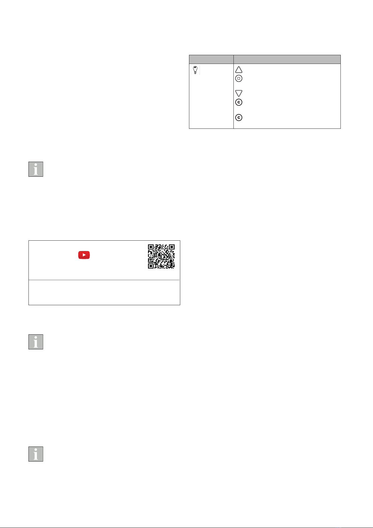
Operation
The WMS Socket always is always of the "light" product
type and is operated as follows, for example on a WMS
Hand-held transmitter:
Product type Functionality
Light Switch on the product
Change the product setting
(ON
→OFF, OFF→ON)
Switch off the product
Short: The product switches to the
stored comfort position
Long: The comfort position for the
product is stored
When the output of the WMS Socket is switched on, the
display lights up on the front.
How to operate the WMS Socket with other WMS transmit-
ters, such as the WMS Central transmitter, is described in
the operating and installation instructions of the respective
WMS transmitter.
Maintenance
There are no parts within the device that require mainte-
nance.
Cleaning
Clean the housing with a soft, dry cloth. Do not use deter-
gents, cleaning agents, solvents, abrasive substances or
steam cleaners!
Liability
Failure to comply with the product information in these
instructions and use of the unit in a manner that contra-
venes its intended use and purpose may result in the
manufacturer refusing to honour warranty claims for
product damage. In this case, liability for secondary harm
to persons or damage to property will also be excluded.
Follow the instructions in the operating manual of your sun
shading system. Liability is also excluded for damage to
the sun shading system resulting from operation under icy
conditions.
Disposal
After use, the device must be disposed of according to
legal regulations or turned in to your local recycling centre.


 User manual")


