MAGNASPHERE N14 W23777 Stone Ridge Dr. Suite 160 Waukesha, WI 53188 tel 262.347.0711 fax 262.347.0710 www.magnasphere.com
Additional mounting hardware, resistor configurations, cable lengths, and other variants are available.
Patents #5673021, #6603378, #8228191, #8314698 & Patents Pending
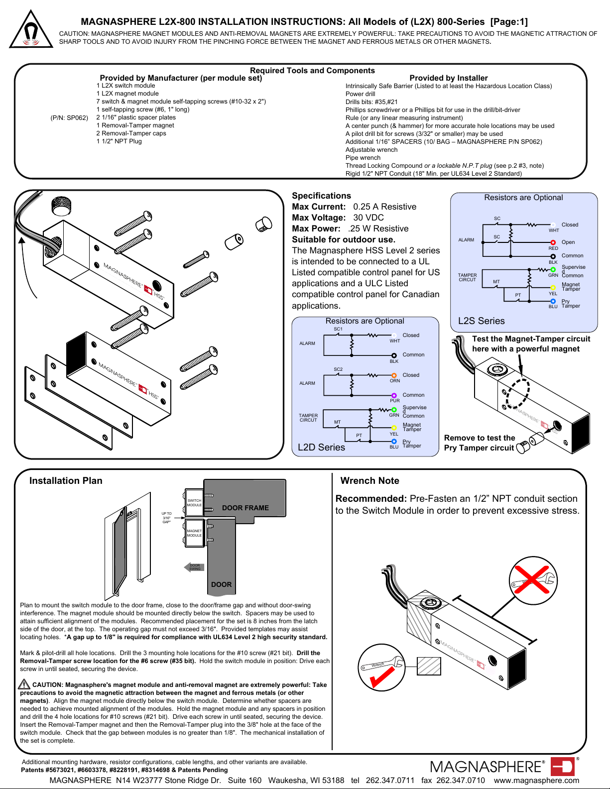
MAGNASPHERE L2X-800 INSTALLATION INSTRUCTIONS: All Models of (L2X) 800-Series [Page:1]
CAUTION: MAGNASPHERE MAGNET MODULES AND ANTI-REMOVAL MAGNETS ARE EXTREMELY POWERFUL: TAKE PRECAUTIONS TO AVOID THE MAGNETIC ATTRACTION OF
SHARP TOOLS AND TO AVOID INJURY FROM THE PINCHING FORCE BETWEEN THE MAGNET AND FERROUS METALS OR OTHER MAGNETS.
Required Tools and Components
Provided by Manufacturer (per module set)
1 L2X switch module
1 L2X magnet module
7 switch & magnet module self-tapping screws (#10-32 x 2")
1 self-tapping screw (#6, 1" long)
2 1/16" plastic spacer plates
1 Removal-Tamper magnet
2 Removal-Tamper caps
1 1/2" NPT Plug
(P/N: SP062)
Provided by Installer
Intrinsically Safe Barrier (Listed to at least the Hazardous Location Class)
Power drill
Drills bits: #35,#21
Phillips screwdriver or a Phillips bit for use in the drill/bit-driver
Rule (or any linear measuring instrument)
A center punch (& hammer) for more accurate hole locations may be used
A pilot drill bit for screws (3/32" or smaller) may be used
Additional 1/16” SPACERS (10/ BAG – MAGNASPHERE P/N SP062)
Adjustable wrench
Pipe wrench
Thread Locking Compound or a lockable N.P.T plug (see p.2 #3, note)
Rigid 1/2" NPT Conduit (18" Min. per UL634 Level 2 Standard)
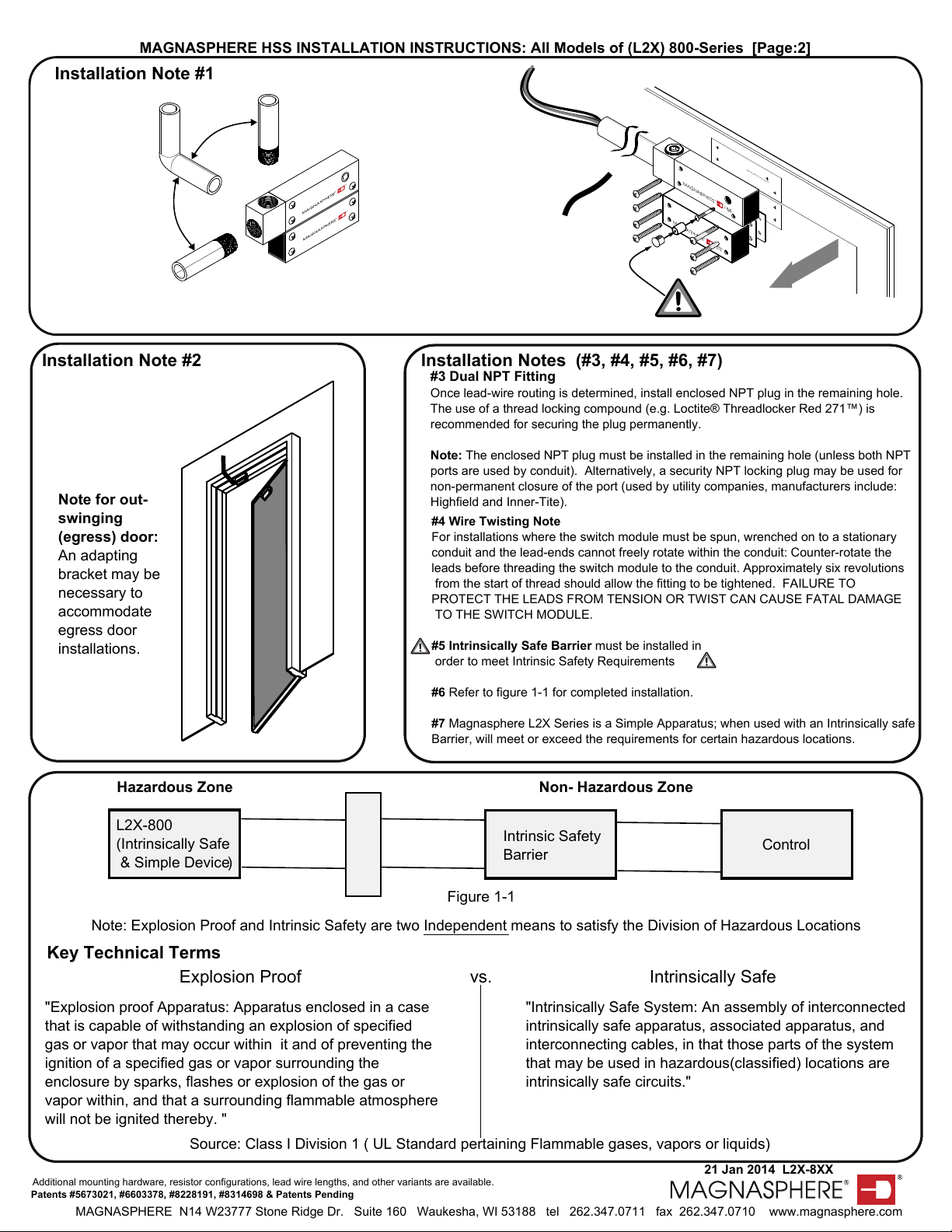
Installation Plan
Plan to mount the switch module to the door frame, close to the door/frame gap and without door-swing
interference. The magnet module should be mounted directly below the switch. Spacers may be used to
attain sufficient alignment of the modules. Recommended placement for the set is 8 inches from the latch
side of the door, at the top. The operating gap must not exceed 3/16". Provided templates may assist
locating holes. *A gap up to 1/8" is required for compliance with UL634 Level 2 high security standard.
Mark & pilot-drill all hole locations. Drill the 3 mounting hole locations for the #10 screw (#21 bit). Drill the
Removal-Tamper screw location for the #6 screw (#35 bit). Hold the switch module in position: Drive each
screw in until seated, securing the device.
CAUTION: Magnasphere's magnet module and anti-removal magnet are extremely powerful: Take
precautions to avoid the magnetic attraction between the magnet and ferrous metals (or other
magnets). Align the magnet module directly below the switch module. Determine whether spacers are
needed to achieve mounted alignment of the modules. Hold the magnet module and any spacers in position
and drill the 4 hole locations for #10 screws (#21 bit). Drive each screw in until seated, securing the device.
Insert the Removal-Tamper magnet and then the Removal-Tamper plug into the 3/8" hole at the face of the
switch module. Check that the gap between modules is no greater than 1/8". The mechanical installation of
the set is complete.
DOOR FRAME
DOOR
SWITCH
MODULE
MAGNET
MODULE
DOOR
SWING
UP TO
3/16"
GAP*
Wrench Note
Recommended: Pre-Fasten an 1/2” NPT conduit section
to the Switch Module in order to prevent excessive stress.
Wrench
X
Wrench
Specifications
Max Current: 0.25 A Resistive
Max Voltage: 30 VDC
Max Power: .25 W Resistive
Suitable for outdoor use.
The Magnasphere HSS Level 2 series
is intended to be connected to a UL
Listed compatible control panel for US
applications and a ULC Listed
compatible control panel for Canadian
applications.
Closed
Open
Common
Supervise
d
Common
Magnet
Tamper
Pry
Tamper
ALARM
TAMPER
CIRCUT
WHT
RED
BLK
GRN
YEL
BLU
SC
SC
MT
PT
L2S Series
Resistors are Optional
Supervise
d
Common
Magnet
Tamper
Pry
Tamper
TAMPER
CIRCUT
GRN
YEL
BLU
Closed
Common
ALARM WHT
SC1
MT
PT
Closed
Common
ALARM ORN
SC2
PUR
BLK
L2D Series
Resistors are Optional
Test the Magnet-Tamper circuit
here with a powerful magnet
Remove to test the
Pry Tamper circuit
SWITCH MODULE
#10 SCREW
#10 SCREWS
#10 SCREWS
MAGNET MODULE
1/16" SPACER
1/16" SPACER
REMOVAL
TAMPER
MAGNET
REMOVAL
TAMPER
CAP
#6 SCREW
#10 SCREWS
1/2" NPT PLUG
22 AWG (36" L)
(Longer leads can be ordered)
Attention: modules à aimants Magnasphere et anti-enlèvement aimants sont très puissants: prendre des précautions pour éviter l'attraction magnétique d'outils
tranchants et à éviter les blessures de la force de pincement entre l'aimant et les métaux ferreux ou d'autres aimants.