Watt Drive V2000 Series User manual

INVERTER
Series V2000
M A N U A L
NB588XA

Manual
Page 2 / 51
MANUAL
These two manuals provide you with a general information how to use V2000 frequency
inverter and how to apply, if needed, special applications.
V2000 Installation manual provides you with the information necessary to install, start-up
and operate the V2000 frequency converters. It is recommended that this manual is read
thoroughly before powering up the frequency converter for the first time.
If any problem occurs, please contact your local distributors. WATT DRIVE Antriebstechnik
GmbH is not responsible for the use of the frequency converters against the instructions.

Manual
Page 3 / 51
WATT DRIVE WORLDWIDE
WATT DRIVE Antriebstechnik GmbH A-2753 Markt Piesting
Tel.: +43/2633/404-0 Fax: +43/2633/404-220 Wöllersdorferstraße 68
Internet: http:\\www.wattdrive.com e-mail: watt@wattdrive.com
Power Drive Services Ltd, Unit 1, Victoria St. Ind. Est. Leigh WN7 5SE U.K.
Tel.: +44 1942260206 Fax: +44 1942260525 e-mail: www.wattdrive.co.uk/contact.htm
WATT DRIVE Süd GmbH D-72379 Hechingen
Tel.: +49/7471/9685-0 Fax: +49/7471/9865-29 e-mail: watt-sued@t-online.de
WATT DRIVE Nord GmbH D-51429 Bergisch Gladbach
Vertriebs- und Servicecenter Köln
Tel.: +49/2204/84-2800 Fax: +49/2204/84-2819 e-mail: watt-koeln@t-online.de
WATT DRIVE D-97044 Würzburg
Vertriebs- und Servicecenter Max LAMB KG
Tel.: +49/931/2794-0 Fax: +49/931/27455 e-mail: ant@lamb.de
WATT EURO DRIVE (Far East) PTE LT SGP-629082 Singapore
Tel.: +65/86 23 220 Fax: +65/86 23 33 e-mail: watteuro@pacific.net.sg
WATT EURO DRIVE (Malaysia) SDN BH 40400 Selangor, Malaysia
Tel: +603/736 89 81 Fax: +603/736 89 76 e-mail: cmfoo98@tm.net.my
Version: BA-FBE_UR.004.R001.06_00
File: H: V2000 Kurzanleitung_englisch.doc
Date: 27hof June 2000 / DE

Manual
Page 4 / 51
Please read this manual carefully before you install and operate an V2000 series inverter and
observe all of the instructions given in there. This manual may also serve as a reference guide und
therefore should always be kept at hand.
Symbols used
There are several safety instructions in this manual which are marked with a special hazard alert
symbol (flash or exclamation mark in the center of a triangle). Additionally, either the word
CAUTION or WARNING is added following the triangle with the exclamation mark.
This symbol means hazardous high voltage. It is used to call your attention to items or
operations that could be dangerous to you or other persons life. Please read the safety
message carefully and follow all the instructions given.
This symbol is used to call your attention to situations which are potentially dangerous to
persons. Please read the safety message carefully and follow all the instructions given.
The safety messages given following this symbol are further divided into two categories:
WARNING This message indicates a situation which may lead to serious injury
or even death if the instruction is not observed.
CAUTION This message indicates a situation which may lead to minor or
moderate injury, or damage of product.
HAZARDOUS HIGH VOLTAGE
Motor control equipment or electronic controllers are connected to hazardous
line voltages. When servicing drives and electronic controllers there might
exist exposed components with cases ore protrusions at or above line
potential. Extreme care should be taken to protect against shock.
For these reasons, the following safety guidelines should be observed:
Stand on an insulating pad and make it a habit to use only one hand when
checking components. Disconnect power before checking controllers or
performing maintenance. Be sure that equipment is grounded properly. Wear
safety glasses whenever working on an electronic controller or rotating
electrical equipment.
WARNING This equipment should be installed, adjusted and serviced only by qualified
electrical maintenace personell familiar with the construction and operation of
the equipment and the hazards involved. Failure to observe this precaution
could result in bodily injury.
WARNING The user is responsible that all driven machinery, drive train mechanism not
supplied by WATT DRIVE Antriebstechnik GmbH, and process line material
are capable of safe operation at an applied frequency of 150% of the
maximum selected frequency range to the AC motor. Failure to do so can
result in destruction of equipment and injury to personnell should a single point
failure occur.
WARNING HAZARD OF ELECTRICAL SHOCK. DISCONNECT INCOMING POWER
BEFORE WORKING ON THIS CONTROL.
WARNING SEPERATE MOTOR OVERLOAD AND OVERCURRENT PROTECTION
DEVICES ARE REQUIRED TO BE PROVIDED IN ACCORDANCE WITH THE
SAFETY CODES REQUIRED BY JURISDICTIONAL AUTHORITIES.
CAUTION These instructions should be read and clearly understood before working on
V2000 series equipment.
CAUTION Proper grounds, disconnecting devices (e.g. fuses) and other safety devices
and their location are the responsibility of the user and are not provided by
WATT DRIVE.

Manual
Page 5 / 51
CAUTION DANGEROUS VOLTAGE EXISTS UNTIL THE POWER LIGHT ON THE
DIGITAL OPERATOR IS OFF.
CAUTION Rotating shafts and electrical potentials above ground level can be hazardous.
Therefore it is strongly recommended that all electrical work conform to the
national electrical codes and local regulations. Installation, maintenance and
alignment should be performed by qualified personnell only.
Factory recommended test procedures included in this instruction manual
should be followed. Always disconnect electrical power before working on the
unit.
WARNING a) Any motor used must be of suitable rating.
b) Motors may have hazardous moving parts so that suitable protection must
be provided in order to avoid injury.
CAUTION Alarm connections may have hazardous live voltages even when the inverter
is disconnected. In case of removing the front cover for maintenance or
inspection, confirm that incoming power for alarm connections is surely
disconnected.
CAUTION Main terminals or other hazardous terminals for any interconnection (terminals
for connecting the motor, contact breaker, filter etc.) must be inaccessible in
end installation.
All of the above instructions, together with any other requirements, reccommendations,
and safety messages highlighted in this manual must be strictly complied with.
NOTES ON EMC (ELECTRO MAGNETICAL COMPATIBILITY)
WARNING This equipment should be installed, adjusted and serviced by qualified
personnell familiar with construction and operation of the equipment and
the hazards involved. Failure to observe this precaution could result in
bodily injury.
When using V2000 series inverters in EU countries, the EMC directive 89/336/EEC must be
observed. To satisfy the EMC directive and to comply with the standard, the following provisions
should be obeyed:
A) Environmental conditions for the inverter:
•Ambient temperature: -10°C to 40°C.
•Relative Humidity: 20% to 90% (no dew condensation)
•Vibrations: max. 5,9m/s2(0.6 g) at 10–55Hz.
•Location: 1000 meter or less altitude, indoors (no corrosive gas or dust).
B) The power supply to the V2000 inverter must conform to the conditions stated below. If one of
the conditions mentioned is not satisfied then an appropriate V2000 AC reactor will have to be
installed.
•Voltage fluctuation +/-10% or less
•Voltage unbalance +/-3% or less
•Frequency variation +/-4% or less
C) Wiring
•Shielded wiring (screened cable) is required for motor wiring, and total length has to be kept
to less than 50m. When using motor cables longer than 50m, V2000 motor filters should be
installed. Directions for installing filters can be found in the V2000 installation manual.
Manual
Page 6 / 51
•Seperate the mains circuit wiring from the wiring used for signals or process circuit. Please
refer to the V2000 installation manual.
D) Installation
•For V2000 series inverters, the filters described hereafter have to be used and the
installation notes have to be observed.
If installed according to the following directions, the frequency inverters comply with the following
standards:
Emmissions: EN 61800-3 (EN 55011 group 1, class B)
Immunity: EN 61800-3, industrial environments
For the best possible damping of interference, special line filters have been developed which
guarantee you easy assembly and installation along with the necessary electrical reliability.
However, effective EMC is only ensured if the suitable filter is selected for the particular drive and
installed in accordance with these EMC recommendations. Please choose the appropriate filter
using the table below:
Inverter type Input voltage Filter type
V2000-002 NFE UHZNF-E-1-007
V2000-004 NFE UHZNF-E-1-007
V2000-005 NFE UHZNF-E-1-007
V2000-007 NFE UHZNF-E-1-012
V2000-011 NFE UHZNF-E-1-012
V2000-015 NFE UHZNF-E-1-024
V2000-022 NFE
1 ~ 220V -10% thru 240V
+5%
UHZNF-E-1-024
V2000-004 HFE UHZNF-F-3-007
V2000-007 HFE UHZNF-F-3-007
V2000-015 HFE UHZNF-F-3-007
V2000-022 HFE UHZNF-F-3-007
V2000-030 HFE UHZNF-F-3-011
V2000-040 HFE UHZNF-F-3-011
V2000-055 HFE UHZNF-F-3-020
V2000-075 HFE
3 ~ 380 V -10% thru 460V
+10%
UHZNF-F-3-020
Note: All filters are designed for 50Hz/60Hz +/-5%.
The amount of line-conducted interference also increases as motor cable length increases.
Adherence to the interference limits for line-conducted interference is guaranteed on following way:
•If maximum motor cable length is 10 m at maximum elementary frequency:
Class „B“.
•If maximum motor cable length is 20 m at elementary frequency 5 kHz:
Class „B“.
•If maximum motor cable length is 50 m at maximum elementary frequency:
Class „A“.
Observe the following provisions for an electromagnetically compatible setup of your drive
system:
1. As user you must ensure that the HF impedance between frequency inverter, filter and ground is
as small as possible.
•Take care that the connections are metallic and have the largest possible areas (zink-plated
mounting plates)
2. Conductor loops act like antennas, especially when they encompass large areas. Consequently:
•Avoid unnecessary conductor loops
•Avoid parallel arrangement of „clean“ and interference-prone conductors

Manual
Page 7 / 51
3. Lay the motor cable and all analog and digital control lines shielded.
•You should allow the effective shield area of these lines to remain as large as possible; i.e.,
do not move the shield further away than absolutely necessary.
•With compact systems, if for example the frequency inverter is communicating with the
steering unit, in the same control cabinet connected at the same PE-potential, the screen of
control lines should be put on, on both sides with PE. With branch systems, if for example the
communicating steering unit is not in the same control cabinet and there is a distance
between the systems, we recommend to put on the screen of control lines only on the side of
the frequency inverter. If it is possible, direct in the cable entry section of the steering unit.
The screen of Motor cabels always must be put on, on both sides with PE.
•The large area contact between shield and PE-potential you can realise with a metal PG
screw connection or a metallic mounting clip.
•Use only copper mesh cable (CY) with 85% coverage
•The shielding should not be interrupted at any point in the cable. If the use of reactors,
contactors, terminals or safety switches in the motor output is necessary, the unshielded
section should be kept as small as possible.
•Some motors have a rubber gasket between terminal box and motor housing. Very often, the
terminal boxes, and particularly the threads for the metal PG screw connections, are painted.
Make sure there is always a good metallic connection between the shielding of the motor
cable, the metal PG screw connection, the terminal box and the motor housing, and carefully
remove this paint if necessary.
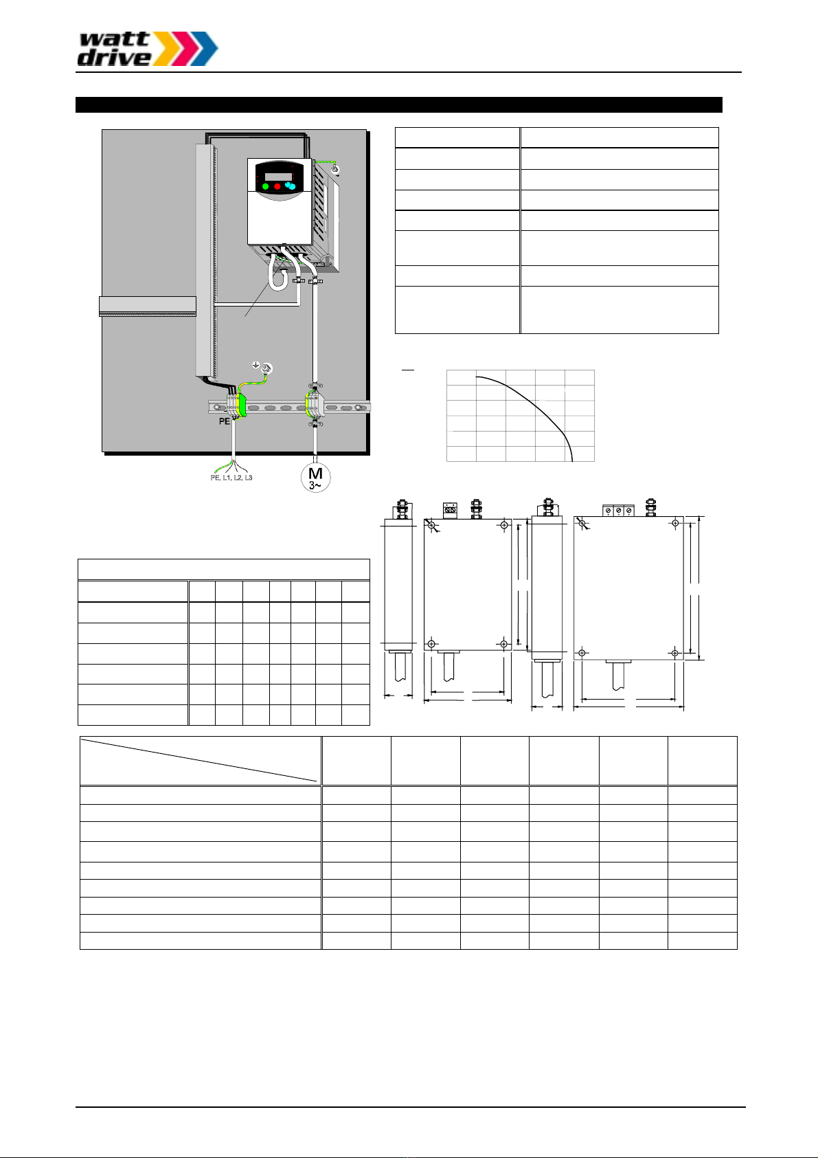
4. Very frequently, interference is coupled in through installation cables. This influence you can
minimize:
•Lay interfering cables separately, a minimum of 0.25 m from cables susceptible to
interference.
•A particularly critical point is laying cables parallel over larger distances. If two cables
intersect, the interference is smallest if they intersect at an angle of 90°. Cables susceptible to
interference should therefore only intersect motor cables, intermediate circuit cables, or the
wiring of a rheostat at right angles and never be laid parallel to them over larger distances.
5. The distance between an interference source and an interference sink (interference-threatened
device) essentially determines the effects of the emitted interference on the interference sink.
•You should use only interference-free devices and maintain a minimum distance of 0.25 m
from the drive.
6. Safety measures
•Ensure that the protective conductor terminal (PE) of the filter is properly connected with the
protective conductor terminal of the frequency inverter. An HF ground connection via metal
contact between the housings of the filter and the frequency inverter, or solely via cable
shield, is not permitted as protective conductor connection. The filter must be solidly and
permanently connected with the ground potential so as to preclude the danger of electric
shock upon touching the filter if a fault occurs. You can achieve this by connecting it with a
grounding conductor of at least 10 mm² or connecting a second grounding conductor,
connected with a separate grounding terminal, parallel to the protective conductor (the cross
section of each single protective conductor terminal must be designed for the required
nominal load).
Manual
Page 8 / 51
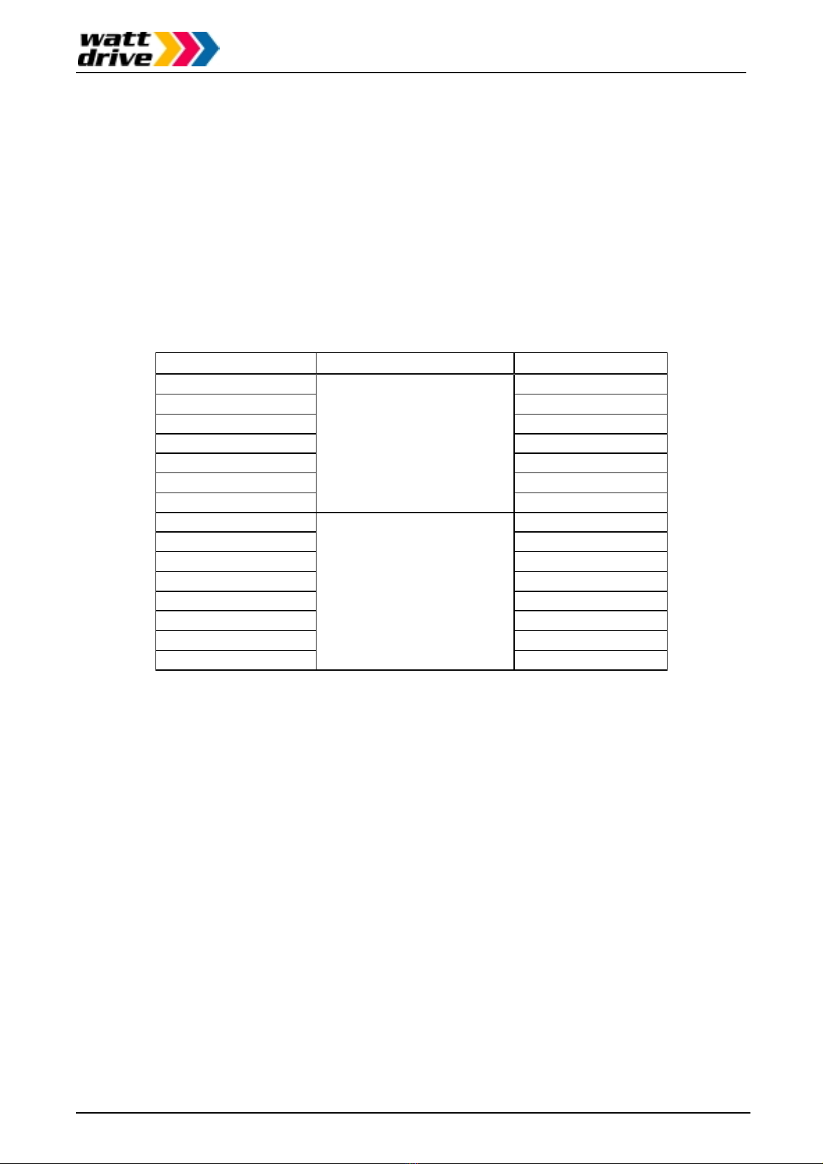
Technical specifications and dimensions of V2000 foot print filter:
WATT DRIVE
55.0
R
U
NSTOP
RESET
MI MAX
RUN
PRG
Hz
A
P
O
WER
2STR
F
U
N
C
.1
V2000
V2000V2000
V2000
WARNING
HAZARD OF PERSONAL I NJURY O
R
ELECTRIC SHOCK
Disconnect incomi n
g
p
ower and wait
5 minutes befor e o
p
enin
g
front case.
PE-connection
Dimensions (in mm)
Model:UHZNF-
Type
ABCDEF
E-1-007 1 120 80 25 110 67 2x6
E-1-012 1 130 110 27 118 98 4x6
E-1-024 1 180 140 29 168 128 4x6
F-3-007 2 130 110 27 118 98 4x6
F-3-011 2 180 140 29 168 128 4x6
F-3-020 2 257 182 35 236 160 4x7
Type: UHZNF-
Specification:
E-1-007 E-1-012 E-1-024 F-3-007 F-3-011 F-3-020
Voltage in V 240 +5% 240 +5% 240 +5% 460 +10% 460 +10% 460 + 10%
Current in A at 40°C 2 x 7A 2 x 12A 2 x 24A 3 x 7A 3 x 11A 3 x 20A
Leak. current in mA/Phase, 50Hz, worst case 1)- - - 32 62 120
Leakage current in mA/ Phase, 50Hz, Un 2)< 3.5 < 3.5 < 15 < 3.5 < 3.5 <10
Test voltage in V DC, 2s ph./ph., ph./ground 1400 / 2800 1400 / 2800 1400 / 1400 1978 / 2800 1978 / 2800 1978 / 1978
Dimensions single wire / litze 4 / 4 mm² 4 / 4 mm² 4 / 4 mm² 4 / 4 mm² 4 / 4 mm² 4 / 4 mm²
Output cable 3x1.5mm² 3x1.5mm² 3x2.5mm² 4x1.5mm² 4x2.5mm² 4x2.5mm²
Weight in kg (approx.) 0.5 0.7 1.0 0.8 1.1 2.4
Heat dissip. in W (approx.) 6 7 9 7 10 14
1 )“Worst case” states the leakage current for three-phase filters in the worst of cases. That means one phase is live
and two phases of the feed-line lead-in are interrupted. These maximum values are based on an operating voltage of
460 V (ph./ph.).
2 )The normal leakage current for three-phase filters is stated. This means the filter is operating on 460 V (ph./.ph.). The
stated values are adhered to up to a neutral voltage of 5V to ground caused by line unbalance.
Current at 40°C ambient temperature
Overload 1.5 x INfor 10min
Frequency 50 / 60 Hz
Material Steel, surface refined
Humidity class C
Operation height < 1000 m without derating;
> 1000 m, IN-2%, for each 1000m
Temperature range -25°C through +85°C
Enclosure
Input terminals IP 20
and PE-holder M5.
Load side: cable, unshielded.
0
0,
2
0
,
4
0
,
6
0
,
8
1
,
0
2
0
4
0
60
80
1
00
Temperature in °C
0
1,2
IB
I
N
=
Dependency of current on ambient temperature:
F
DA
E
B
C
Type 1
F
D
A
E
B
C
Type 2

Manual
Page 9 / 51
Contents
1. Safety precautions ...................................................................................................10
Installation...................................................................................................................10
Wiring .........................................................................................................................10
Control and operation .................................................................................................11
Maintenance and inspection .......................................................................................12
Others.........................................................................................................................12
2. Inspection upon unpacking.....................................................................................14
3. External dimensions and terminal positions..........................................................15
4. Technical specifications..........................................................................................16
5. Appearance and names of parts .............................................................................18
6. Installation ................................................................................................................20
7. Wiring........................................................................................................................21
Wiring the power supply and motor.............................................................................21
Wiring the control terminals.........................................................................................22
General remarks .........................................................................................................23
Wiring equipment and options.....................................................................................24
Terminals....................................................................................................................26
8. General operation notes ..........................................................................................29
Before starting operation.............................................................................................29
Test run ......................................................................................................................29
9. Control circuit terminal functions ...........................................................................32
Overview.....................................................................................................................32
10. Using the digital operator ......................................................................................34
The digital operator control panel................................................................................34
Operating procedure example.....................................................................................34
Digital operator keys ...................................................................................................35
11. Messages................................................................................................................36
Trip messages ............................................................................................................47
Other messages .........................................................................................................48
12. Trouble shooting....................................................................................................49
Protective functions.....................................................................................................51

Safety precautions
Page 10 / 51
1. Safety precautions
Installation
The following safety precautions are to be observed when installing the frequency inverter:
CAUTION Be sure to install the inverter on flame resistant material such as metal.
Otherwise, there is a danger of fire.
CAUTION Be shure not to place anything inflammable in the vicinity. Otherwise, there is
a danger of fire.
CAUTION Be sure not to let foreign matter (such as cut wire refuse, spatter from
welding, iron refuse, wires, dust etc.) enter the inverter. Otherwise, there is a
danger of fire.
CAUTION Install the inverter in a room which is not exposed to direct sunlight and is
well ventilated. Avoid environments which tend to be high in temperature,
high in humidity or which have dew condensation, as well as places with
dust, corrosive gas, explosive or inflammable gas, grinding-fluid mist, salt
damage etc. Otherwise, there is a danger of fire.
CAUTION The wall surface on which the inverter is mounted must be of a nonflammable
material, such as a steel plate.
Wiring
WARNING The inverter has to be grounded properly. Otherwise, there is a danger of
fire.
WARNING Wiring work must only be carried out when the power supply is off.
Otherwise, there is a danger of electric shock and/or fire.
WARNING Before carrying out the wiring work, the inverter has to be mounted properly.
Otherwise, there is a danger of electric shock or injury.
CAUTION Make shure that the input voltage is as follows (please also refer to chapter
11):
Single/three phase: 200~240V, 50/60Hz (models up to 2,2kW)
Three phase: 200~240V, 50/60Hz
Three phase: 380~460V, 50/60Hz
CAUTION Don´t connect AC power supply to the inverter output terminals U, V, and W.
Otherwise, there is a danger of injury and/or fire.
Safety precautions
Page 11 / 51
INPUTS
(L1) (N)
L1 L2 L3
OUTPUTS
(T1) (T2) (T3)
U V W
Note
)
Power
su
pp
l
y
Note) Terminals L1, N: single phase power supply
Terminals L1, L2, L3: three phase power supply
Not allowed
CAUTION Remarks for using earth leakage circuit breakers in the mains supply:
Frequency inverters with CE-filters (RFI-filter) and screened motor cables have
a higher leakage current against earth. Especially in the moment of switching
this can cause unintentional triggering of earth leakage circuit breakers.
Because of the rectifier on the input side of the inverter there is the possibility
to stall the switch-off function through amounts of DC current. For these
reasons, the following items should be observed:
Only pulse current sensitive earth leakage circuit breakers which have a short
term delay and a higher trigger current (500mA) should be used. Other
components should be secured with separate earth leakage circuit breakers.
Earth leakage circuit breakers in front of an inverter´s rectifier are not an
absolute protection against direct touching.
CAUTION Each phase of the power supply has to be provided with a fuse. Otherwise,
there is a danger of fire.
Control and operation
WARNING Be sure to turn on the input power supply only after closing the front case.
While being energized, don´t open the front case. Otherwise, there is a
danger of electric shock.
WARNING Never operate the switches with wet hands. Otherwise, there is a danger of
electric shock.
WARNING If the retry mode is selected, the inverter may suddenly restart during a stop
which was caused by a trip. In such a case, be sure not to approach the
machine. Provisions have to be taken that the driven motor or machine does
not endanger personnell even in the case of a sudden restart. Otherwise,
there is a danger of injury.
WARNING Even if the power supply is cut off for a short period of time, the inverter may
restart operation after the power supply has recovered if the operation
command is given. If this may incur danger to personnell, provisions have to
be made in order to prevent a restart after power recovery. Otherwise, there
is a danger of injury.
WARNING The STOP key is effective only if the corresponding parameters have been
set. Otherwise, there is a danger of injury.
WARNING If a reset is carried out following a trip condition the motor will restart if the
operation command has been given. Be sure to acknowledge this trip
condition with a reset only after confirming that no operation command is
active. Otherwise, there is a danger of injury.
WARNING When the power to the inverter is turned on while the operation command
is active the motor starts immediately. So before turning power supply on be
sure to confirm that no operation command is active.
Safety precautions
Page 12 / 51
WARNING If the inverter has been configured for the stop command not to be given
using the STOP key, pressing the STOP key does not stop the motor. In
this case a separate emergency stop switch is necessary.
CAUTION Operate the motor and machine connected to the inverter only within the
manufacturer´s speed specifications. Otherwise, there is a danger of injury.
CAUTION If a motor is to be operated at a frequency higher than the standard setting
value of 50 or 60Hz, be sure to check the allowable speed of the motor and
the machine with each manufacturer, and operate them only after getting
their consent.
CAUTION Check the following during and after the test run. Otherwise, there is a
danger of machine breakage:
Was the short cut bar between terminals +1 and + removed by mistake?
Was the running direction of the motor correct?
Was the inverter tripped during acceleration or deceleration?
Were the indications of the rpm and the frequency meter correct?
Were there any abnormal motor vibrations or noise?
Maintenance and inspection
WARNING Before carrying out maintenance and inspection wait for at least five minutes
after having turned off the input power supply. Otherwise, there is a danger of
electric shock.
WARNING When removing connectors (e.g. from fans and printed circuit boards) never
pull the attached wires. Otherwise, there is a danger of fire due to wire
breakage and/or injury.
Others
CAUTION Withstand voltage tests and insulation resistance tests (megger tests) are
executed before the units are shipped, so that there is no need to conduct
these tests before operation.
CAUTION Do not attach or remove wiring or connectors when power is applied. Also, do
not check signals (e.g. using a multimeter) during operation.
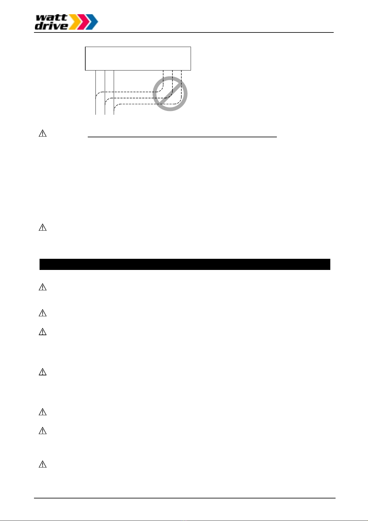
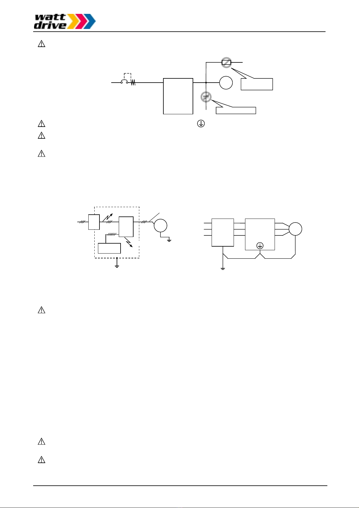
CAUTION Never stop motor operation by switching off the electromagnetic contactors on
the primary or secondary side of the inverter.
Moto
r
Inverte
r
Earth leakage
circuit breake
r
L1
(
L1
)
L2
L3
(
N
)
T1
(
U
)
T2
(
V
)
T3
(
W
)
Power
su
pp
l
y
S2
F
W
P2
4
CORRECT: Start and sto
p
usin
g
FW
S1
WRONG: Start and stop
usin
g
secondar
y
side
WRONG: Start and stop
usin
g
p
rimar
y
side contacto
r
When there has been an instantaneous power failure, and if an operation
instruction has been given, then the inverter may restart operation after the
power failure has ended. If there is a possibibility that such an occurrence may
harm humans, then install an electromagnetic contactor on the primary (power
supply) side of the inverter, so that the circuit does not allow automatic
restarting after the power supply has recoverd. If the optional remote operator
is used and the retry function has been selected, this will also cause automatic
restarting when an operation instruction has been input, so please be careful.
Safety precautions
Page 13 / 51
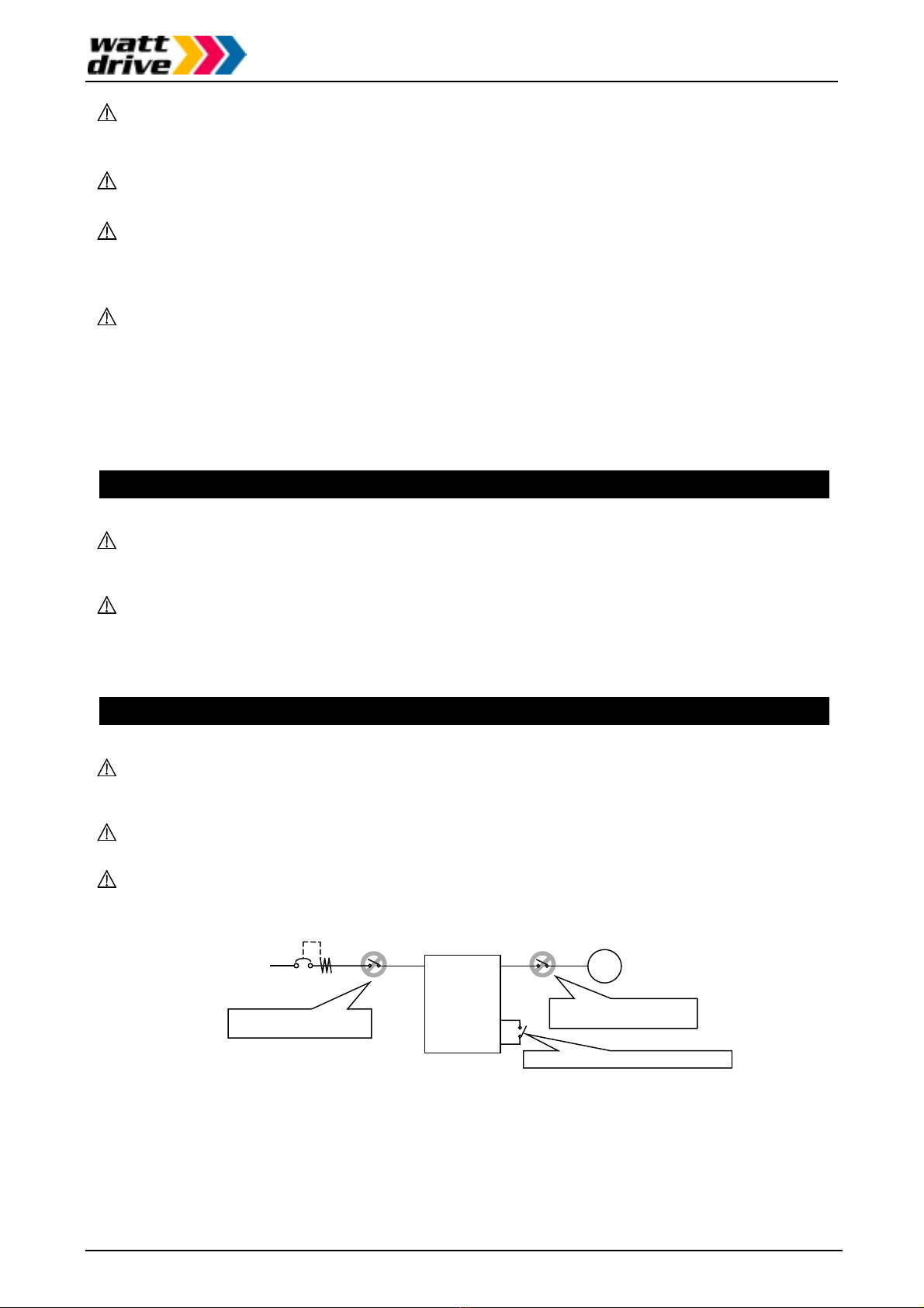
CAUTION Do not insert leading power factor capacitors or surge absorbers between the
output terminals of the inverter and the motor.
Moto
r
Inverte
r
Earth leakage
circuit breake
r
L1
(
L1
)
L2
L3
(
N
)
T1
(
U
)
T2
(
V
)
T3
(
W
)
Power
su
pp
l
y
WRONG: Ca
p
acito
r
WRONG:
Sur
g
e absorbe
r
CAUTION Be sure to ground the grounding terminal properly.
CAUTION Before inspecting the unit wait at least five minutes before opening the inverter
.
CAUTION PROTECTION AGAINST NOISE INTERFERENCE FROM THE INVERTER
V2000 series inverters use many semiconductor switching elements such as
transistors and IGBTs. For this reason, a radio set or measuring instrument
located near the inverter is susceptible to noise interference. To protect the
instruments from erreneous operation due to noise interference produced by
the inverter, they should be installed well apart from the inverter. It is also
effective to shield the whole inverter structure (refer to figure below, left part).
Motor
Inverte
r
L1(L1)
L2
L3(N)
T1(U)
T2(V)
T3(W)
R2
S2
T2
Powe
r
supply
R1
S1
T1
EMI filte
r
Grounding
Inverte
r
EMI
filter
Remote
operator
Motor
Powe
r
supply
Noise
Noise
Grounde
d
frame
Completely ground the frame
with as short a wire as possible.
Grounded piping
or shielded wire
Addition of an EMI filter on the input side of the inverter also reduces the effect
of noise from commercial power lines on external devices (refer to figure
above).
CAUTION EFFECTS OF DISTRIBUTER LINES ON INVERTERS
In the cases mentioned below involving a general purpose inverter, a large
peak current flows on the power supply side, sometimes destroying the
converter module:
A) The unbalance factor of the power supply is 3% or higher.
B) The power supply capacity is set at least ten times greater than the
inverter capacity (i.e. 500kVA or more)
C) When abrupt power supply changes are to be expected. Some examples:
1) Several inverters are interconnected using a short bus to the same
power supply.
2) A thyristor converter and an inverter are interconnected using a short
bus.
3) An installed power factor compensating device is connected or
disconnected.
In the cases mentioned above we recommend installing an AC reactor of 3%
voltage drop at rated current with respect to the supply voltage on the power
supply side.
CAUTION When an EEPROM error occurs (trip E 08) all parameter values have to be
checked for correctness (especially the RS input).
CAUTION When the intelligent digital inputs FW or RV are configured as normally closed
contact (standard setting is normally open), then the inverter starts

Safety precautions
Page 14 / 51
automatically. Do not configure these inputs as normally closed inputs unless
absolutely necessary.
GENERAL NOTICE
In all the illustrations and figures in this manual, covers and safety devices are
occasionally omitted in order to better describe the details. When the inverter
is operated make shure that all the covers and safety devices are placed in
their correct positions.
2. Inspection upon unpacking
Please check the shipment by the time of delivery for damages and completeness. Check that the
inverter and the accompanying instruction manual has been provided. Using the specification label
attached to the side of inverter make sure that the inverter model delivered is the one you ordered.
The specifications included on the specification label are described below:
In the illustration below, the contents of the model designation used for V2000 series inverters is
explained:
UHGV2000 -004 H F E 5
Inverter series
Version number ( _, 1, 2 ...)
Distribution fo
r
(E: Europa U: USA)
Type of inverte
r
(F: with digital operator)
Input voltage
(N: 200V single / three phase)
(H: 400V three phase)
(L: three phase 200V only)
Motor capacit
y
002: 0.20kW 022: 2.20kW
004: 0.40kW 030: 3.00kW
005: 0.55kW 037: 3.70kW
007: 0.75kW 040: 4.00kW
011: 1.10kW 055: 5.50kW
015: 1.50kW 075: 7.50kW
Applicable motor capacity
Model designation
Inverter input specifications
Inverter output specifications
Manufacturin
g
numbe
r
Input current single phase
Input current three phase
Rated current
Manufacturing date
WATT Drive Antriebstechnik GmbH
Model : V2000-004NFE
In
p
ut/Ein
g
an
g
: 50
,
60Hz 200-240 V 1Ph 5
,
8 A
50
,
60Hz 200-240 V 3Ph
Output/Ausgang: 1-360Hz 200-240 V 3Ph 2,6 A
MFG No. 78B T1128270005 Date:
Tel.: +43/2633/404-0; e-mail: watt@wattdrive.com NE16452-2
HP/kW : ½ / 0.4
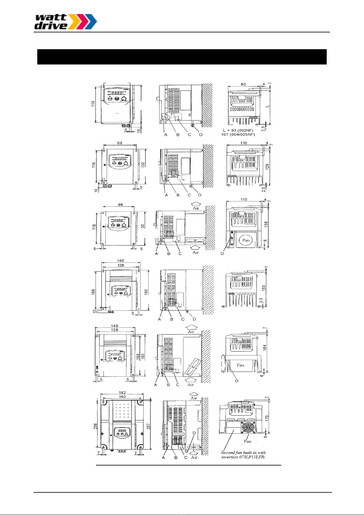
External dimensions and terminal positions
Page 15 / 51
3. External dimensions and terminal positions
98 110 4
118
130
10
5
129
7
2,5
DCB
A
98
110 4
118
130
5
156 7
6
D
CB
A
5
Air
Air
Fan
140
180
153 7
3,5
D
CB
A
128
168
10
5
140
CB
A
5
Air
Air
128
5
168
180
164 7
D
6
Fa
n
Legend:
AControl terminals BAlarm terminals
CMain terminals DGroundin
g
terminals
(
All dimensions are in millimeters
)
V2000
V2000
V2000
V2000
V2000
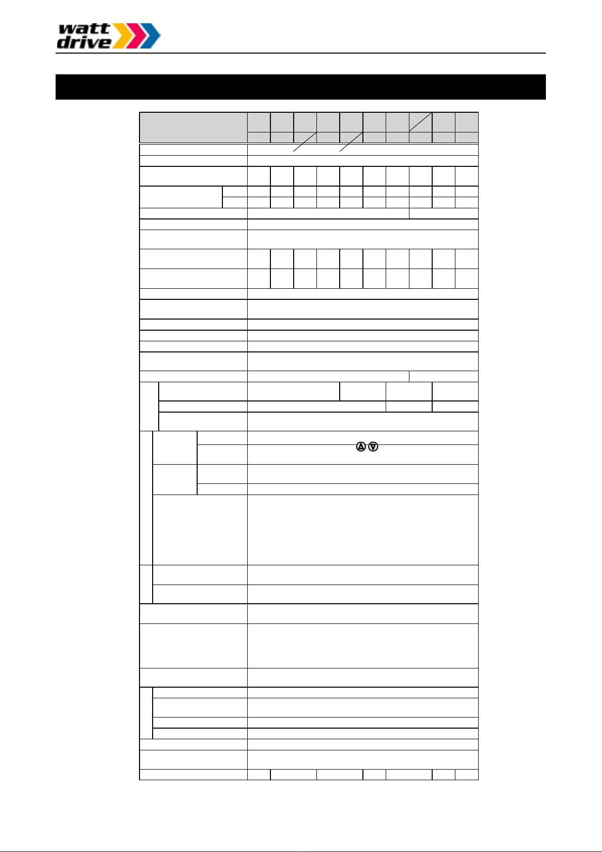
Technical specifications
4. Technical specifications
002
NFE
004
NFE
005
NFE
007
NFE
011
NFE
015
NFE
022
NFE
Inverter V2000-
(200V series)
Protective structure (Note 1)IP20
Overvoltage category III
Maximum motor size (4P)
in kW (Note 2)0.2 0.4 0.55 0.75 1.1 1.5 2.2
230V 0.6 1.0 1.1 1.5 1.9 3.1 4.3
Maximum capacity
in kVA 240V 0.6 1.0 1.2 1.6 2.0 3.3 4.5
Input supply phase Single phase / Three phase Three phase
Rated input voltage 200VAC -10% ~ 240VAC +5% 50/60Hz +/-5%
Rated output voltage
(Note 3)
Three phase 200 ~ 240VAC
(Corresponds to input voltage)
Rated input current in A
Single phase (Three phase)
3.5
(2.0)
5.8
(3.4)
6.7
(3.9)
9.0
(5.2)
11.2
(6.5)
17.5
(10.0)
24.0
(14.0)
Rated output current in A
(Note 4a)1.4 2.6 3.0 4.0 5.0 8.0 11.0
Output frequency range 0,5 ~ 360 Hz (Note 5)
Frequency accuracy
(at 25°C +/-10°C)
Digital command: +/-0.01% of maximum frequency
Analog command: +/-0.1% of maximum frequency
Frequency setting resolution Digital setting: 0.1Hz Analog setting: maximum frequency /1000
Voltage/frequency characterist. Constant, reduced or high starting (SLV) torque
Overload current capacity 150% during 60 seconds (once per 10 minutes)
Acceleration/deceleration time 0.1 ~ 3000 s in selectable linear and non-linear mode
(second acceleration/deceleration usable)
Starting torque (using SLV) >200% >180%
Dynam. braking, feedback
to capacitor (Note 6)approx. 100% approx. 70% approx. 20% approx. 30%
using ext. braking resistor approx. 150% approx. 100% approx. 80%
DC injection braking Brakin
g
is on at the minimum fre
q
uenc
y
or less
(
minimum fre
q
uenc
y
,
braking time and braking force can be set)
Dig. operator Settings using keys or potentiometer
Frequenc
y
setting External
signals
0-10VDC (input impedance 10k Ohm), 4-20mA (input impedance
250 Ohm), Pot 1k-2k Ohm, 1W (055 ~ 075LFU/LFR: 2W)
Dig. operator Via keys RUN (for start) and STOP/RESET (for stop)
(Default setting: forward run)
Forward /
Reverse run
(Start/Stop) Ext. signals Intelligent input terminals configurable as FW and RV
Intelligent input terminals
programmable as
FW: Forward run start/stop RV: Reverse run start/stop
CF1–CF4: Multistage speed JG: Jogging command
AT: Analog current input selection 2CH: 2.Accel./decel. time
FRS: Free run stop EXT: External trip
USP: USP function RS: Reset
SFT: Software lock PTC: Thermal protection
DB: Ext. DB input SET: 2. setting active
UP: Acceleration (Remote) DWN: Decelerat. (Remote)
Intelligent output terminals
programmable as
FA1/FA2: Frequ. arrival signal RUN: Motor running signal
OL: Overload signal OD: PID deviation signal AL: Alarm signal
Frequency and current
monitoring
Connection of external analog meter (0-10VDC, max. 1mA) for
frequency or current; connection of external digital frequency meter
Fault alarm contact On when inverter trips (1c contact).
Alternatively usable as intelligent output terminal
Other functions
Autotuning, Automatic voltage regulation, retry; analog gain/vias
ad
j
ustment, fre
q
uenc
y
j
um
p
, u
pp
er/lower limiter, out
p
ut fre
q
ue
n
c
y
display, trip history monitoring, carrier frequency setting, PID
control, automatic torque boost, USP function, 2. Setting function,
ON/OFF control of cooling fan, and many more
Protection functions Overcurrent, overvoltage, undervoltage, electronic thermal, temp-
erature abnormality, ground fault, overload, CT error, BRD error
Ambient temp. (Note 7)-10 ~ 50°C
Storage temperature and
humidity
-25 ~ 70°C (during short term transportation period only)
20 ~ 90% RH (no dew condensation)
Vibration Max. 5,9m/s2(=0,6g) at 10-55Hz
Installation location 1000m or less altitude indoors (IP54 or equivalent)
External color Grey
Options Remote operator, copy unit, cable for digital operator,
reactor for improving power factor, noise filter,
Overall weight (approx.) 0.7 0.8 1.3 2.3 2.8 5.5 5.7
Braking
torque
Inputs
OutputsEnvironmental

Technical specifications
Page 17 / 51
Inverter V2000-
(400V series)
004
HFE
007
HFE
015
HFE
022
HFE
030
HFE
040
HFE
055
HFE
075
HFE
Protective structure (Note 1)IP20
Overvoltage category III
Maximum motor size (4P)
in kW (Note 2)0.4 0.75 1.5 2.2 3.0 4.0 5.5 7.5
Maximum capacity
in kVA 460V 1.1 1.9 2.9 4.2 6.2 6.6 9.9 12.2
Input supply phase Three Phase
Rated input voltage 380VAC -10% ~ 460VAC +10% 50/60Hz +/-5%
Rated output voltage
(Note 3)
Three Phase 360 ~ 460VAC
(Corresponds to input voltage)
Rated input current in A 2.0 3.3 5.0 7.0 10.0 11.0 16.5 20.0
Rated output current in A
(Note 4b)1.5 2.5 3.8 5.5 7.8 8.6 13.0 16.0
Output frequency range 0.5 ~ 360 Hz (Note 5)
Frequency accuracy
(at 25°C +/-10°C)
Digital command: +/-0.01% of maximum frequency
Analog command: +/-0.1% of maximum frequency
Frequency setting resolution Digital setting: 0.1 Hz
Analog setting: max. frequency / 1000
Voltage/frequency characterist. Constant, reduced or high starting (SLV) torque
Overload current capacity 150% during 60 seconds (once per 10 minutes)
Acceleration/deceleration time 0.1 ~ 3000 s in selectable linear and non-linear mode
(second acceleration/deceleration usable)
Starting torque (using SLV) > 200% > 180%
Dynam. braking, feedback
to capacitor (Note 6)approx. 100% approx.
70% approx. 20% approx. 30%
External braking resistor approx. 150% approx. 100% approx. 80%
DC injection braking Braking is on at the minimum frequency or less (minimum frequency,
braking time and braking force can be set)
Dig. operator Settings using keys or potentiometer
Frequenc
y
setting External
signals
0-10VDC (input impedance 10k Ohm)
4-20mA (input impedance 250 Ohm)
Potentiometer 1k-2k Ohm, 1W (055 ~ 075LFU/LFR: 2W)
Dig. operator Via keys RUN (for start) and STOP/RESET (for stop)
(Default setting: forward run)
Forward /
Reverse run
(Start/Stop) Ext. signals Intelligent input terminals configurable as FW and RV
Intelligent input terminals
programmable as
FW: Forward run start/stop RV: Reverse run start/stop
CF1–CF4: Multistage speed JG: Jogging command
AT: Analog current input selection 2CH: 2.Accel./decel. time
FRS: Free run stop EXT: External trip
USP: USP function RS: Reset
SFT: Software lock PTC: Thermal protection
DB: Ext. DB input SET: 2. setting active
UP: Acceleration (Remote) DWN: Decelerat. (Remote)
Intelligent output terminals
programmable as
FA1/FA2: Frequency arrival signal
RUN: Motor running signal OL: Overload signa
l
OD: Deviation signal at PID control AL: Alarm signal
Frequency and current
monitoring
Connection of external analog meter (0-10VDC, max. 1mA) for
frequency or current; connection of external digital frequency meter
Fault alarm contact On when the inverter trips (1c contact).
Alternatively usable as intelligent output terminal
Other functions
Autotuning, Automatic voltage regulation, retry; analog gain/vias
adjustment, frequency jump, upper/lower limiter, output freque
n
c
y
display, trip history monitoring, carrier frequency setting, PID
control, automatic torque boost, USP function, 2. Setting function,
ON/OFF control of cooling fan, and many more
Protection functions Overcurrent, overvoltage, undervoltage, electronic thermal, temp-
erature abnormality, ground fault, overload, CT error, BRD error
Ambient temperature -10 ~ 50°C (Note 7)
Storage temperature and
humidity
-25 ~ 70°C (during short term transportation period only)
20 ~ 90% RH (no dew condensation)
Vibration Max. 5.9m/s2(=0.6g) at 10-55Hz
Installation location 1000m or less altitude indoors (IP54 or equivalent)
External color Grey
Options Remote operator, copy unit, cable for digital operator,
reactor for improving power factor, noise filter
Overall weight (approx.) 1.3 1.7 2.8 5.5 5.7
Braking
torque
InputsOutputsEnvironmental

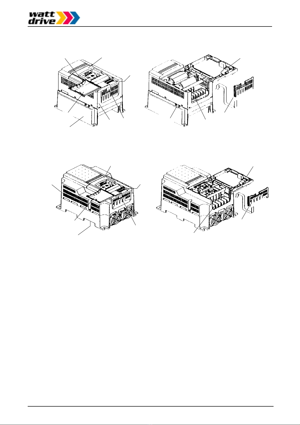
Appearance and name of parts
5. Appearance and names of parts
Key cove
r
(Note 1)
Casin
g
Coolin
g
fi
n
Digital operator
(can be opened)
(Note 2)
Coolin
g
fi
n
Serial
interface
Casin
g
Screw
(Note 2)
Key cover
(Note 1)
Digital operator
(can be opened)
(Note 2)
Serial
interface
Screw (Note 2)
Control terminals
Grounding
terminal (PE)
Grounding
terminal (PE)
Control terminals
Alarm terminals
Rear cove
r
Mains circuit
terminals Rear cover
Mains circui
t
terminals
Alarm terminals
Note 1: The key cover can be opened by hand without any additional tool.
Note 2: The screw must be loosened before the digital operator can be opened.
Appearance and name of parts
Page 19 / 51
KEY COVER
(
OPENED
)
CASING
COOLING FIN
SERIAL
INTERFACE
DIGITAL OPERATOR
(CAN BE OPENED)
(Note 2)
SCREW
(
Note 2
)
GROUNDING
TERMINAL
(
PE
)
REAR COVER
CONTROL
TERMINALS
MAINS CIRCUIT
TERMINALS
ALARM
TERMINAL
KEY COVER
(OPENED)
CASING
COOLING FIN
SERIAL
INTERFACE
DIGITAL OPERATOR
(CAN BE OPENED)
(Anm.2)
KEY COVER
CONTROL
TERMINAL
MAINS CIRCUIT
TERMINALS
ALARM
TERMINALS
Note 1: The key cover can be opened by hand without any additional tool.
Note 2: The screw must be loosened before the digital operator can be opened.

Installation
Page 20 / 51
6. Installation
The inverter must be mounted vertically on a non-flammable wall in order to prevent from
overheating and fire. The minimum clearances to the surrounding walls shown in the figure below
must be complied with to ensure a good ventilation. Foreign matter (especially conductive objects)
must nut be dropped into the inverter since they not only cause malfunction and damage but may
also lead to electrical and fire hazards.
Cover all ventilation holes on the inverter during installation so that no foreign objects can enter the
inverter. Be sure to remove those covers from the inverter before you put the inverter to work.
a
pp
rox. 10c
m
approx. 8cm
approx.
12cm
Inverter
Air flo
w
The inverter must be installed vertically
(do not install it on the floor or horizontally)
Wall or mounting surface
The mounting base must be a non-
flammable material (e.g. metal)
a
pp
rox. 10c
m
The minimum clearances to the surrounding walls shown in the figure are only meant for reference.
A more compact installation (back to back) may well be possible and should be discussed with
WATT DRIVE. Please always leave enough room for the key cover to be opened without problems
in order to connect wires to the control terminals.
The ambient temperature should be in the range of -10°C to 50°C. At a temperature of 40~50°C
the carrier frequency has to be reduced to 2kHz, the output current must be kept below 80% of the
rated current, and the top cover (see figure below) has to be removed. Higher ambient temperature
causes shorter inverter life. So if there is hot equipment in the vicinity of the inverter, keep it away
from the inverter as far as possible.
If the inverter is to be installed in a cabinet, ambient temperature is considered to be the
temperature prevailing withing this cabinet. Fans have to be provided if necessary so that ambient
temperature remains within the limits specified above.
For safety reasons the digital operator must be closed and not be opened during inverter operation.
The end application must be in accordance with the BS EN 60204-1 standard.
To
p
cove
r
Ventilation holes
(
on either side
)
Table of contents
Other Watt Drive Inverter manuals


Popular Inverter manuals by other brands


Siemens
Siemens SINAMICS G120P Technical manual

Hoymiles
Hoymiles MI-300T user manual

Trannergy
Trannergy TRM025KTL user manual

Yingli Solar
Yingli Solar PANDA 108CELL 182TOPCon Installation and user manual

Santerno
Santerno SUNWAY TG610 1000V TE OD installation guide

Mitsubishi Electric
Mitsubishi Electric FR-F700 Series Instruction manual supplement