Table of Contents
1. About This Manual................................................................ 1
1.1 Scope .................................................................
1
1.2 Intended Audience ..............................................
1
1.3 Symbols Used .....................................................
1
1.4 How to use this manual .......................................
1
2. Safety .................................................................................
2
2.1 Product Description ............................................
2
2.2 Important Safety Instructions ...............................
2
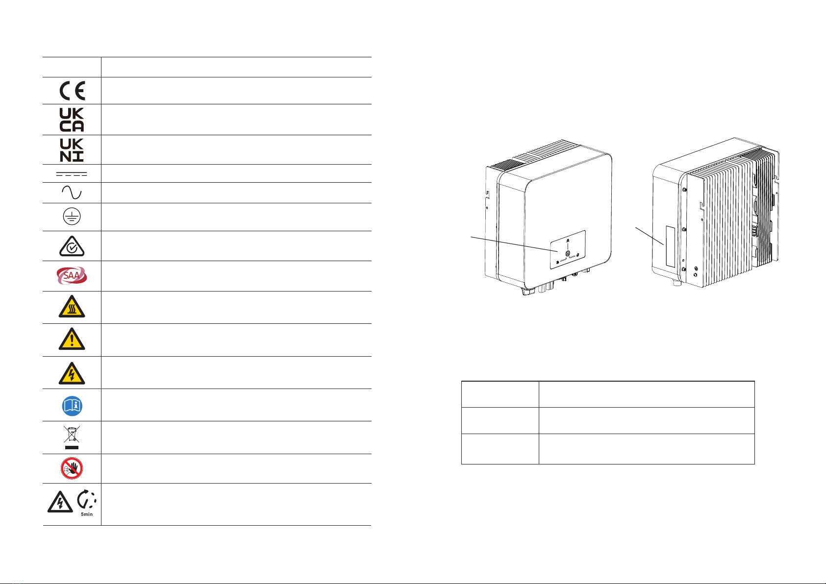
2.3 Symbol on the Type Label
...................................
4
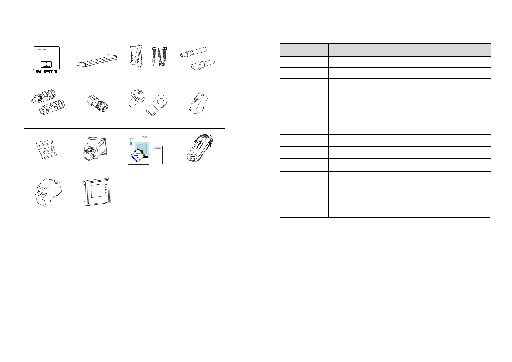
4. Scope of Delivery ..............................................................
10
3. Product Overview ................................................................
5
3.1 View of the Inverter ............................................
5
3.2 Dimension ........................................................
6
5. Mechanical Mounting .......................................................
12
5.1 Requirements for Mounting
.............................. 12
5.2 Mounting Instructions ...................................... 17
6. Electrical Connection ........................................................
18
6.1 PV Connection ................................................
19
6.2 Grid Output Connection ..................................
22
6.5 Wi-Fi Connection ............................................ 32
7. System Operation ............................................................. 36
7.1 Powering ON the Inverter ................................ 36
7.2 Powering OFF the Inverter ............................... 36
7.3 LEDs and Graphical Display ............................ 37
9. Troubleshooting ............................................................... 41
11. Dis c la i m e r........................................................................
6.3 ............................ 26
6.4 ......................................... 31
Earth Connection
Communication Connection
3.3 Terminal of the Inverter
.......................................
7
..............................................
9
3.4 System Dimension
12. Warranty Card Registration...............................................
8. Communication Mode Descript i o n .................................... 39
1 0 . Technical Data.................................................................
6.7 Installation Verication .................................... 35
6.6 AFCI (optional) ............................................... 34
45
51
53