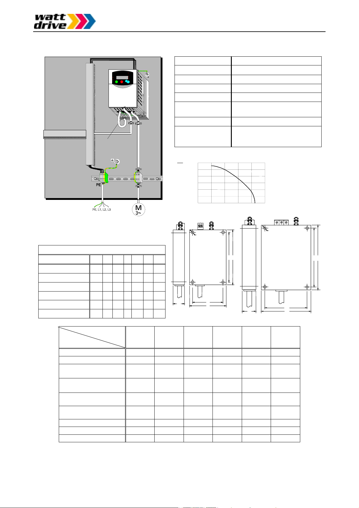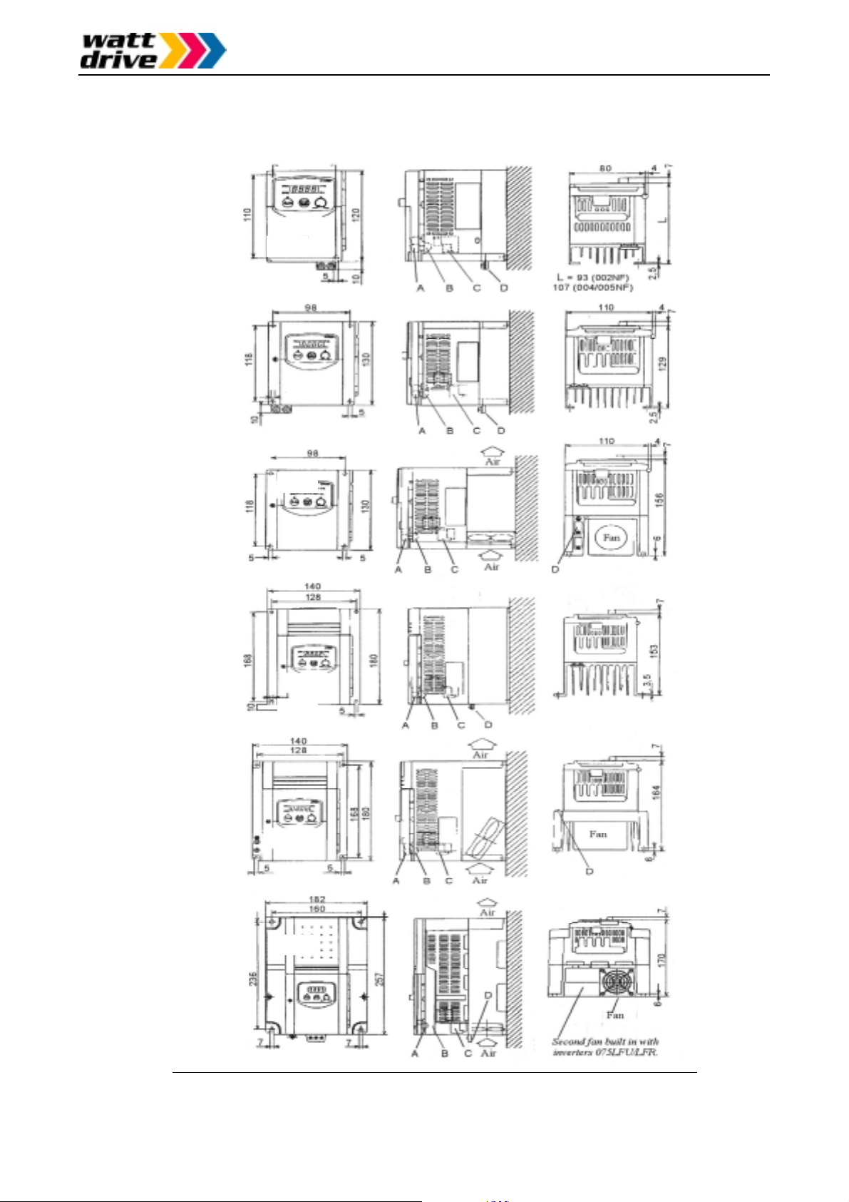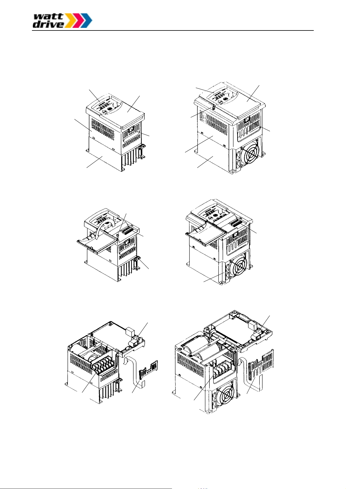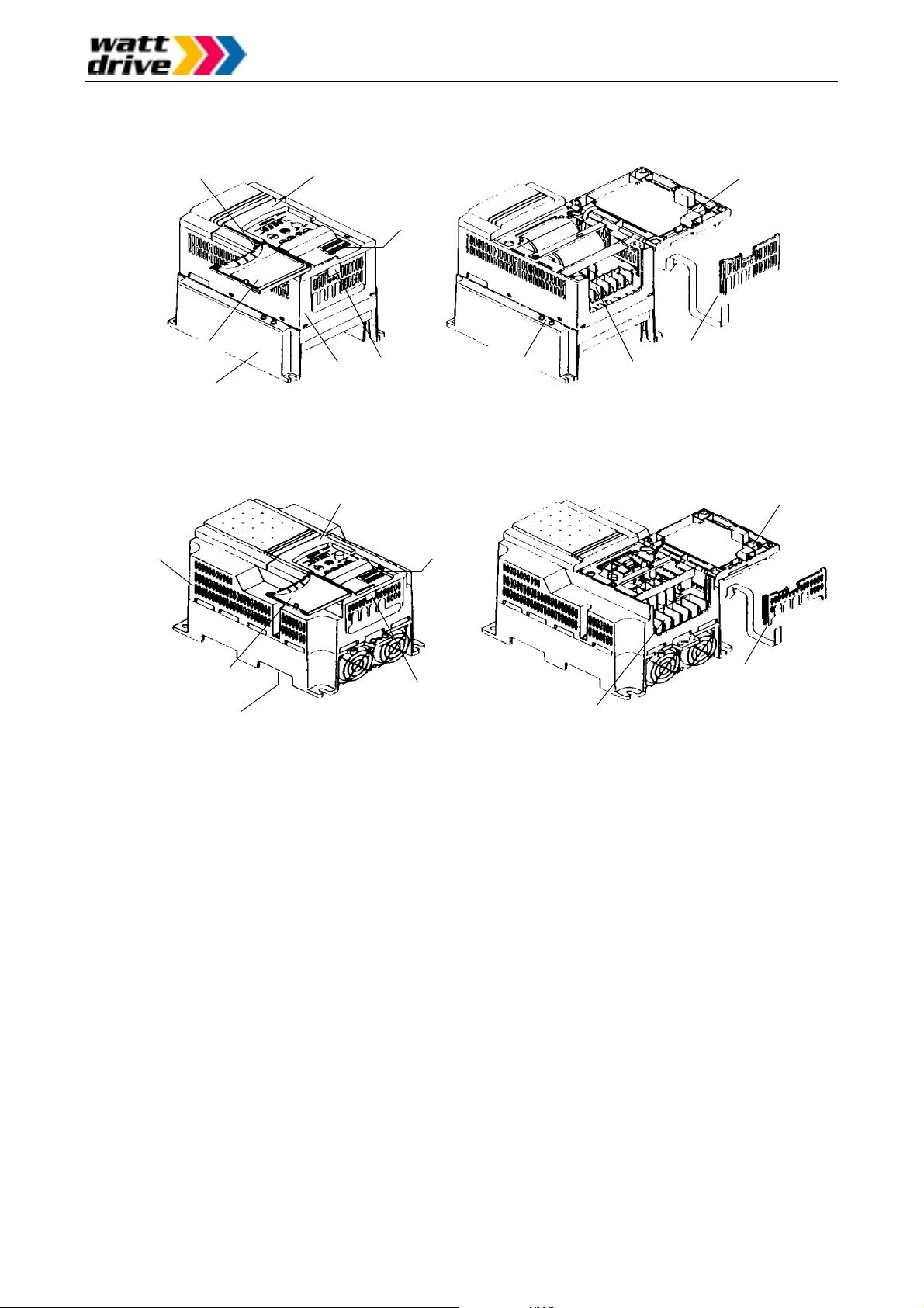
Appearance and names of parts
Page 15 / 52
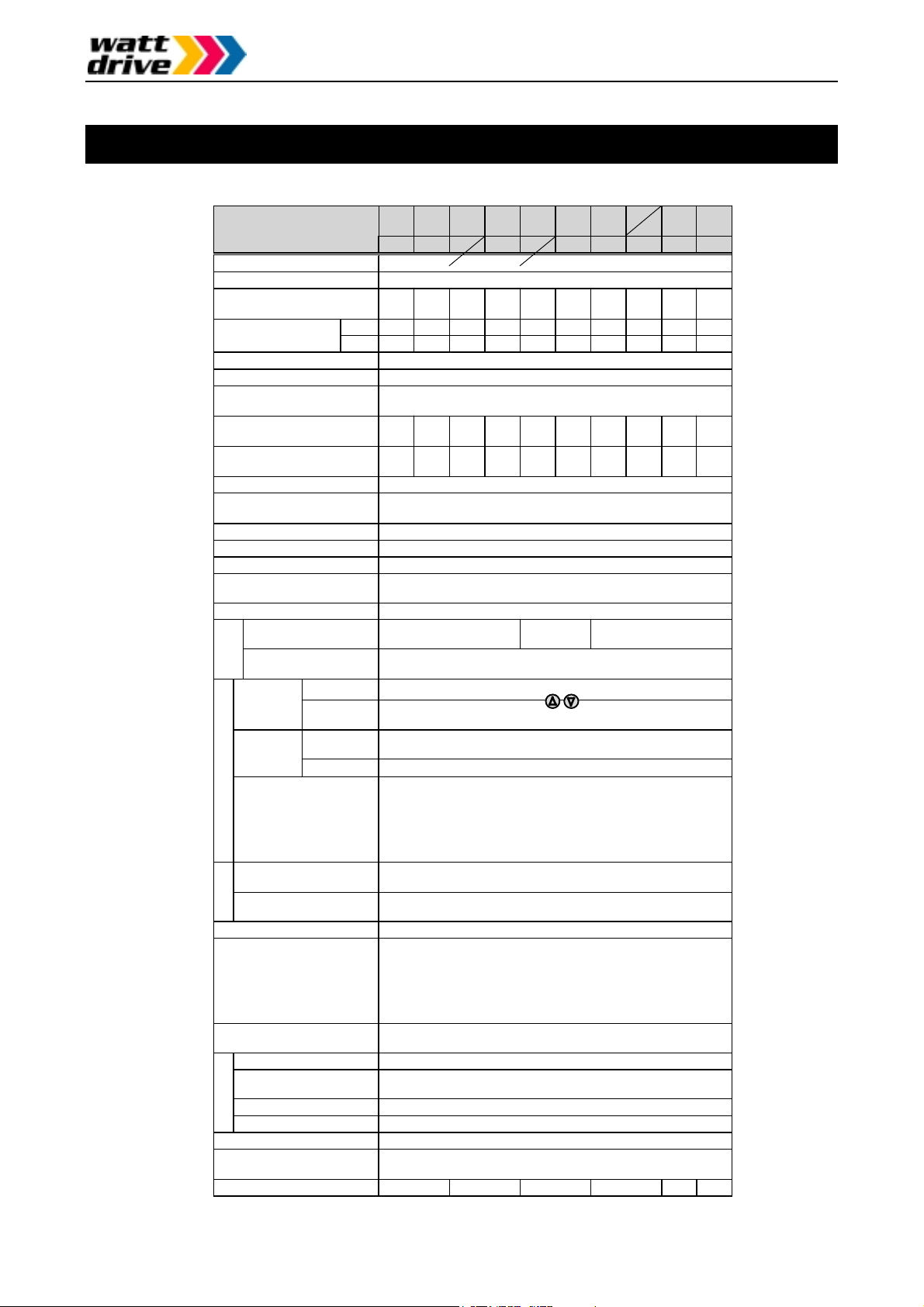
3. Technical specifications
NFE
NFE
NFE
NFE
NFE
NFE
NFE
Inverter L 200 0-
(200V series)
Protective structure (Note 1)IP20
Overvoltage category III
Maximum motor size (4P)
in kW (Note 2)0.2 0.4 0.55 0.75 1.1 1.5 2.2 3.7 5.5 7.5
230V 0.5 1.0 1.1 1.5 1.9 2.8 3.9 6.3 9.5 12.7
Maximum capacity
in kVA 240V 0.5 1.0 1.2 1.6 2.0 2.9 4.1 6.6 9.9 13.3
Input supply phase 002 ~ 022NFE/U: Single phase / 3 phase 037 ~ 075LFU: 3 phase
Rated input voltage 200VAC –10% ~ 240VAC +5% 50/60Hz +/-5%
Rated output voltage
(Note 3)
Three phase 200 ~ 240VAC
(Corresponds to input voltage)
Rated input current in A
Single phase (Three phase)
1.8
3.4
3.9
5.2
6.5
9.3
13.0
-
20.0
-
30.0
-
40.0
Rated output current in A
(Note 4a)1.4 2.6 3.0 4.0 5.0 7.1 10.0 15.9 24.0 32.0
Output frequency range 0.5 ~ 360 Hz (Note 5)
Frequency accuracy
(at 25°C +/-10°C)
Digital command: +/-0.01% of maximum frequency
Analog command: +/-0.2% of maximum frequency
Frequency setting resolution Digital setting: 0.1Hz Analog setting: maximum frequency /1000
Voltage/frequency characterist. Constant or reduced torque with any variable voltage/frequency
Overload current capacity 150% during 60 seconds (once per 10 minutes)
Acceleration/deceleration time 0.1 ~ 3000 s in selectable linear and non-linear mode
(second acceleration/deceleration usable)
Starting torque 100% or more (when torque boost has been set)
Dynam. braking, feedback
to capacitor (Note 6)ca. 100% ca. 70% ca. 20%
DC injection braking Braking is on at the minimum frequency or less (minimum
frequency, braking time and braking force can be set)
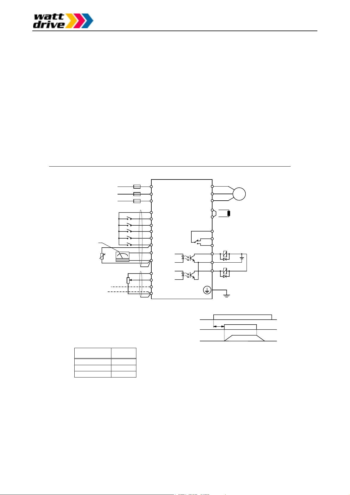
Dig. operator Settings using keys or potentiometer
setting External
signals
0-10VDC (input impedance 10k Ohm); 4-20mA (input
impedance 250 Ohm); Potentiometer 1k-2k Ohm, 1W
Di
. o
erator Via keys RUN (for start) and STOP/RESET (for stop)
(Default setting: forward run)
Forward /
Reverse run
Start/Sto
Ext. signals Intelligent input terminals configurable as FW and RV
Intelligent input terminals
programmable as
FW: Forward run start/stop RV: Reverse run start/stop
CF1–CF4: Multistage speed JG: Jogging command
AT: Analog current input selection 2CH: 2.Accel./decel. time
FRS: Free run stop EXT: External trip
USP: USP function RS: Reset
SFT: Software lock PTC: Thermal protection
Intelligent output terminals
programmable as
FA1/FA2: Frequ. arrival signal RUN: Motor running signal
OL: Overload signal OD: PID deviation signal AL: Alarm signal
Frequency and current
monitoring
Connection of external analog meter (0-10VDC, max. 1mA) for
fre
uenc
or current
connection of external di
ital fre
uenc
meter
Fault alarm contact On when the inverter trips (1c contact)
Other functions
Automatic voltage regulation, retry;
analog gain/vias adjustment, frequency jump,
upper/lower limiter, output frequency display,
trip history monitoring, carrier frequency setting,
PID control, automatic torque boost,
and many more
Protection functions Overcurrent, overvoltage, undervoltage, electronic thermal,
temperature abnormality, ground fault upon starting, overload limit
Ambient temp. (Note 7)-10 ~ 50°C
Storage temperature and
humidity
-25 ~ 70°C (during short term transportation period only)
20 ~ 90% RH (no dew condensation)
Vibration Max. 5.9m/s2(=0.6g) at 10-55Hz
Installation location 1000m or less altitude indoors (IP54 or equivalent)
External color Blue
Options Remote operator, copy unit, cable for digital operator,
reactor for improving power factor, noise filter
Overall weight (approx.) 0.85 1.3 2.2 2.8 5.5 5.7
Bra
ng
torque
Inputs
OutputsEnvironmental.