Elk Products ELK-120 User manual

PO Box 100 • Hildebran, NC 28637 USA • 828-397-4200 Voice • 828-397-4415 Fax
http://www.elkproducts.com • email: info@elkproducts.com
07/11
APPLICATION:
The ELK-120 v.3 features 4 channels that can be
congured as 2 channels of siren and 2 channels of
voice, or all 4 channels can be used for voice. Either
way the voice channels are fully recordable and are
stored in non-volatile memory. Total time of recording
is 8 minutes. The Siren channels oer a choice of: Classic
Yelp Sound, Temporal Coded Horn, or Industrial Horn.
Multi-Channel Recordable Voice Module And Siren
FEATURES:
• Four Channels Congurable as: Two Siren and Two Recordable Voice OR Four Recordable Voice. Maximum
record time is 8 minutes divided between the number of voice channels
• Siren Sounds: Classic Yelp Siren, Temporal Coded Horn, and Pulsing Industrial Horn
• Temporal Coded Horn meets ANSI standard for Audible Emergency Evacuation Signaling
• Recordings stored in non-volatile memory
• Voice channels accept momentary triggers
• “One Shot” or Continuous voice playback settings
• Built-in condenser microphone for recording
• Adjustable speaker volume and current draw
• Powerful 24 watt audio amplier for Speakers
• Line Level Output for Paging Systems and Ampliers
• PC sound card interface connector
• Lifetime Limited Warranty
SPECIFICATIONS:
• Operating Voltage: 11 to 14 Volts D.C.
• Adjustable current draw: 1/4 to 1.8 Amps
• Low current triggers: 9 to 14 Volts DC @ 30 mA
• Maximum sound level: 122 dB @ 1 meter
• Maximum speaker loading: 4 Ohms
• Pulsing input: 1/2 to 1.5 Sec Pulse, 50% duty cycle
• Size: 3” x 5” x 1.25” (76 x 127 x 32 mm)
ELK-120 v3
Features or Specications subject to change without notice.

OPERATION
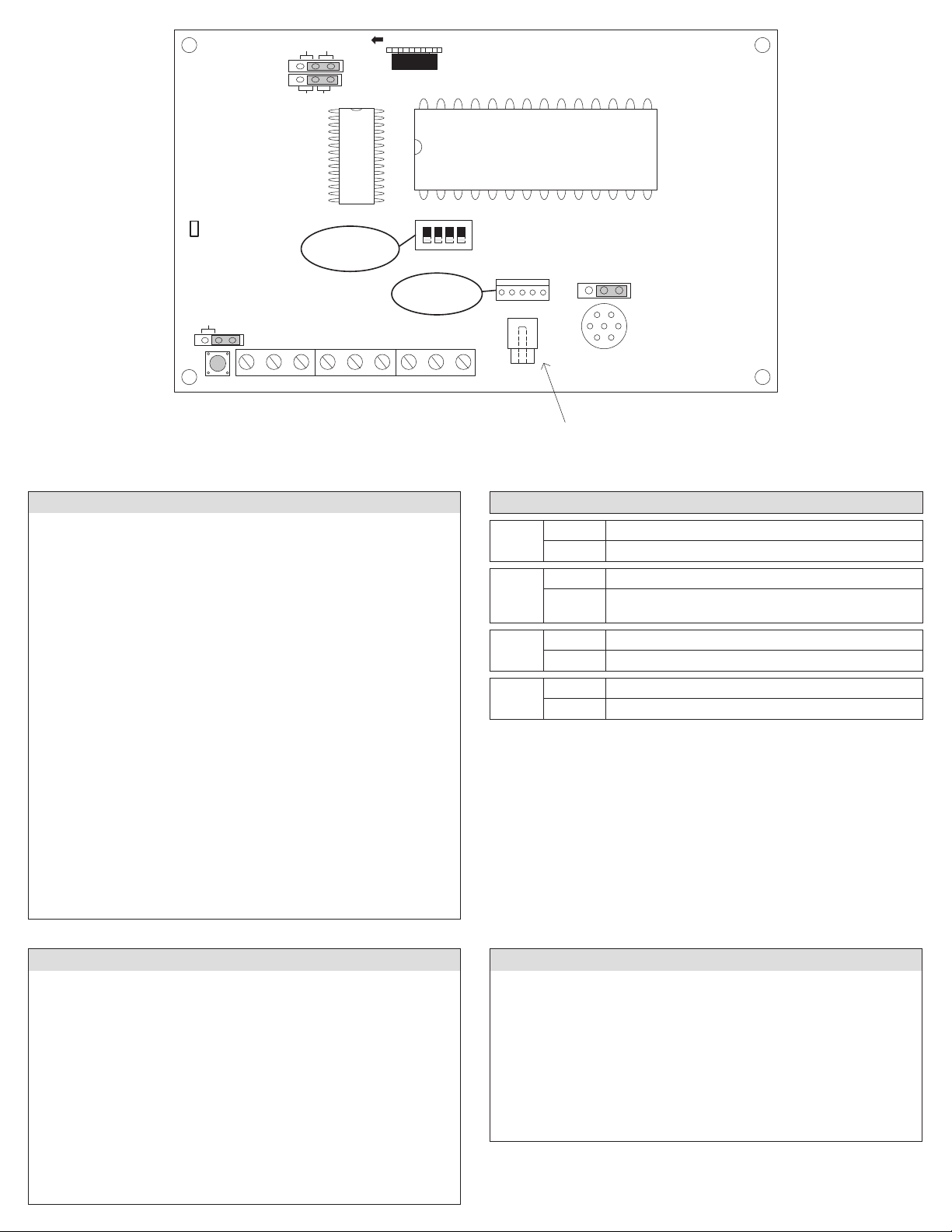
The 4 channels of the ELK-120 must be congured by Jumper JP4, located in the top left corner of the board. With JP4 in the Siren position the unit will be
congured as 2 recordable voice channels and 2 xed siren sounds. With JP4 in the Voice position, the unit will be congured as 4 recordable voice channels.
Voice messages are stored in non-volatile memory and may be re-recorded as needed. Simply congure Jumper JP4 according to your choice of operation
and connect according to one of the installation diagrams and the following instructions.
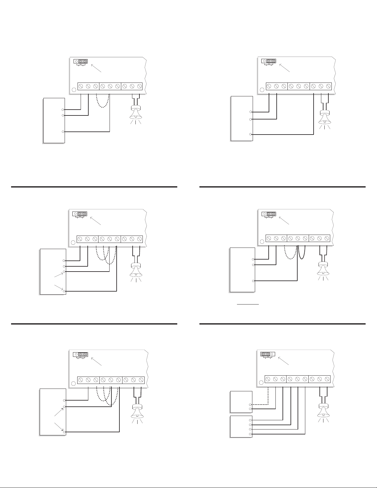
SIREN with VOICE mode
(Jumper JP4 in the SIREN position)
In this mode the 4 channels are split into 2 siren and 2 voice. The siren
channels are +S3 (Yelp) and +B4 (Temporal Coded Horn). The voice
channels are +V1 and +V2 and have 4 recordable minutes each or 8
minutes combined.
Positive (+) Voltage Activation Terminals
Each channel may be activated by applying 12 Volts DC between the
NEG terminal and the positive (+) input. Both a siren and voice channel
may be activated at the same time to achieve mixed siren and voice
output.
+V1 = Recordable Voice Channel 1 input.
+V2 = Recordable Voice Channel 2 input.
+S3 = Yelp Siren input.
+B4 = Temporal Coded Horn input.
Pulsing Voltage Activation
Terminals +S3 and +V1 can automatically detect a pulsed versus a steady
activation and play the alternate channel. For example: if channel +S3
(Yelp) is pulsed then channel +B4 (Horn) will be played. If channel +V1
(Voice 1) is pulsed then channel +V2 (Voice 2) will be played.
Negative (-) Activation Terminal
There is a single terminal marked -VS for controls (eg: DSC) that switch
the negative of the alarm output. This terminal automatically plays the
appropriate siren and voice combination based upon the input being
a steady or a pulse. If the input is a steady negative, the Yelp Siren and
Recordable Voice 1 will play. If the input is a pulsed negative, the Horn
and Recordable Voice 2 will play. Refer to the wiring diagram.
Mixing Siren Sounds and Voice Messages
To combine a siren sound with a voice message apply +12 Volts DC to
both a Siren input and a Voice input at the same time. EG: To obtain a
Yelp siren followed by a burglary voice message, +12 Volts DC voltage
to channel +S3 and +V1 at the same time. The two channels will
alternately play until the trigger is removed. Exception: Voice channels
can be set to play only once per activation cycle by placing jumper JP2
to the 1SHOT position. The siren sound(s) continue until the activation
input is removed.
VOICE Only mode
(Jumper JP4 in VOICE position)
In this mode the 4 channels are all voice recordable and can hold up to 2
minutes of messages each. Two or more channels can be combined into
longer messages up to the combined maximum of 8 minutes.
Positive (+) Voltage Activation
To activate a channel simply apply 12 Volts DC between the NEG terminal
and the positive (+) channel input. Multiple channels can be combined
(activated at the same time) to achieve mixed playback of voice sounds.
+V1 = Recordable Voice Channel 1 input.
+V2 = Recordable Voice Channel 2 input.
+S3 = Recordable Voice Channel 3 input.
+B4 = Recordable Voice Channel 4 input.
NOTE: Pulsing Voltage Activation is not available in Voice Only Mode.
Instructions Common To Both Modes
Volume and Current Adjust
Turning the Volume knob clockwise will increase the output volume.
The louder the volume, the higher the current draw. The volume and
current draw may be adjusted to match the current capability of the
power source.
Connecting A Constant Power Source
(To Allow Activation By Low Current Devices)
By connecting the +12V and NEG terminals to a constant power source
the current draw of the channel inputs can be reduced to approximately
30 milliamps since all the operating power will then be drawn from the
constant power source. A constant power source also allows a voice
channel to be activated by a momentary voltage and then nish playing
until the end.
Options for Playback of the Voice Channels
The switches marked "Activate Channels" are provided for programming
and for user convenience where manual activation of the channel(s)
may be desired. A constant power source must be connected to +12V
and NEG terminals in order to use these switches.
The 1SHOT position of Jumper JP2 restricts playback of a voice channel
to only once per activation cycle. The channel activation must be
removed and then re-applied before the message will be allowed to
play again. NOTE: 1SHOT does not work with a pulsing activation.
The REPEAT position of Jumper JP2 permits the voice channel to play
repeatedly for as long as the channel input is activated.
Recording Voice Messages
Messages may be recorded from the on-board microphone, or from a PC
with a sound card and an ELK-129 interface.
To record from the onboard microphone place Jumper JP1 in the
MIC position, JP2 in the REPEAT position, and JP3 in the RECORD
position. Activate the desired channel either by using the on-board DIP
switches(requires power to be applied to +12V and NEG terminals) or
by applying +12 Volts DC to the desired input (+V1, +V2, +S3, or +B4).
The current message (if any) will start to play. While it is playing, press
and hold the record switch SW1 and speak clearly into the on-board
microphone. Note that the REC/EOM LED should light before you begin
speaking. To minimize any noise, gently release SW1 after speaking.
The new message will immediately be played. To stop the playback turn
o the channel switch or remove the trigger voltage. To re-record the
message, or to record another channel, repeat the above procedure.
To record with the ELK-129 sound card interface place Jumper JP1 in the
PRG position, and JP2 in the REPEAT position. Plug the ELK-129 ve pin
ribbon cable into Programmer Connector J1. Power the ELK-129 and
move the SW1 slide switch to CH1(this will provide power to the ELK-
120). Select the channel to record with the on-board DIP switch. Follow
the instructions for the ELK-129, Play a "scripted" WAV.

INSTALLATION & HOOKUP EXAMPLES
Note: Dashed Lines Indicate Optional Connections.
Hookup to a Single (one) Alarm Output with a steady / pulse option.
Set JP4 to Siren. A Steady +12 Volts DC applied to +S3 activates the
Siren sound. A 1/2 to 1.5 second Pulse to +S3 activates the Horn sound.
Adding a wire jumper between +S3 and +V1 will combine the Siren
sound with Voice 1 Channel, or Pulsing +S3 combines the Horn sound
with Voice 2 Channel.
Hookup to a Switched Negative Single (one) Alarm Output with a
steady / pulse option.
Set JP4 to Siren. This method is great for Controls that switch their
negative alarm output (eg: DSC). A Steady Negative to terminal -VS
plays the Siren sound combined with Voice 1 Channel. A 1/2 to 1.5
Second Pulse to terminal -VS plays the Horn sound combined with Voice
2 Channel.
Momentary or Low Current Trigger Method: One or two positive
alarm outputs capable of 30 mA.
Set JP4 to Siren. The operating current is drawn from the constant +12
Volts DC power source. The +V1 and +B3 channel trigger terminals draw
only 30 mA each from the control alarm outputs.
Industrial Horn Siren Sound
Set JP4 to Siren. Industrial horn will play if +S3 and +B4 are connected
and activated together. Adding a wire jumper between +S3 and +V1
will combine the Horn with Voice 1 Channel.
Standard Method: Control panel with two alarm outputs capable of
2 Amps max. each.
Set JP4 to Siren. All current must be supplied from the Burg and Fire
Outputs on the Control. Average current draw with 8 Ohm speaker load
is 1.2 Amps, or 1.8 Amps with 4 Ohm load.
Voice Mode
Set JP4 to Voice. A recordable voice channel may be played by
connecting 12 Volts DC between the NEG terminal and the positive
(+) channel input. For low current triggering of a channel, or to have
messages play through to the end when activated by a momentary
trigger, connect terminal +12V to a constant +12 Volt DC source.
8 Ohm
Speaker
Control
Switched
Positive + Alarm
Output
Negative
+12vdc Power
+V1+12V NEG +B4+V2 +S3 SPEAKER-VS
ELK-120
SIREN VOICE
JP4
Set JP4 to Siren
+V1+12V NEG +B4+V2 +S3 SPEAKER-VS
ELK-120
SIREN VOICE
JP4
Set JP4 to Siren
8 Ohm
Speaker
DSC Control
Switched
Negative -
Alarm Output
Negative
+12vdc Alarm
Output
+V1+12V NEG +B4+V2 +S3 SPEAKER-VS
ELK-120
SIREN VOICE
JP4
Set JP4 to Siren
8 Ohm
Speaker
Control
+ Burglar Output
+ Fire Output
Negative
Low Current
Positive Outputs
+12vdc Power
+V1+12V NEG +B4+V2 +S3 SPEAKER-VS
ELK-120
SIREN VOICE
JP4
Set JP4 to Siren
8 Ohm
Speaker
Control
+ Burglar Output
Negative
+12vdc Power
+V1+12V NEG +B4+V2 +S3 SPEAKER-VS
ELK-120
SIREN VOICE
JP4
Set JP4 to Siren
8 Ohm
Speaker
Control
+ Burglar Output
+ Fire Output
Negative
High Current
Positive Outputs
+V1+12V NEG +B4+V2 +S3 SPEAKER-VS
ELK-120
SIREN VOICE
JP4
Set JP4 to Voice
8 Ohm
Speaker
Power
Source
+12V Output
Negative
+12vdc Power
+12V Output
+12V Output
+12V Output

+V1 ELK-120 REC/PLAY MODULE
SW1
+12V NEG
R21
INCREASE VOLUME
JP1
MICPRG
ELK-120 v3
PROGRAMMER
REC
/EOM
MICROPHONE
RECORD +B4+V2 +S3 SPEAKER-VS
SIREN VOICE
JP4
LINE OUT
ACTIVATE
CHANNELS
REPEAT1SHOT
JP2
DISABLE
RECORD
LED
Line Level Output (RCA Jack)
for connecting to the input of a
paging system or audio amplifier
Connects to
optional ELK-129
Selects Channel to
Play/Record
ELK PRODUCTS, INC.
HILDEBRAN, NC 28637
JP3
1234
Figure 1
Summary of Connection Terminals & Switches
[+12V] If using a constant 12 Volt DC power source, connect the positive side here. Nominal
operating range of the ELK-120 is 11 to 14 Volts DC. This input is only required if: A. The -VS
negative trigger terminal is used. B. Momentary activation of the channels is desired. C. The
activating source equipment is current limited to 30 mA or less.
[NEG] Connect to the negative side of the 12 Volt DC power source. Also connect the nega-
tive from external trigger inputs here if they are from another power source.
[+V1] Positive trigger input for Voice channel 1
[+V2] Positive trigger input for Voice channel 2
[+S3] Positive trigger input for Yelp Siren or Voice channel 3
[+B4] Positive trigger input for Temporal Coded Horn or Voice channel 4
[-VS] Negative trigger input for controls with a switched negative output
[SPEAKER] Connect to 8 ohm speaker. (Max 4 Ohm load)
[Volume Control (R21)] Adjusts volume of the speaker output.
[Activate Channels] Selects channel to be recorded. Power must be applied to the +12V
and NEG terminals to use this switch.
[Record Switch (SW1)] To record a message, set JP1 to MIC, activate desired channel, press
SW1, then speak your message into the on-board microphone.
[Programmer (J1)] The optional ELK-129 Computer Sound Card Interface module connects
to this 5 pin connector to allow computer WAV sound les to be downloaded into the ELK-
120.
[Line Out (J2)] This RCA type connector provides line level sound output for connection to
Public Address ampliers
NOTE: Channels may be combined to mix the output
Siren with Voice Mode (JP4 = Siren)(for Alarm Applications)
+V1 = 0 to 8 Minute Recordable Message, see note
+V2 = 0 to 4 Minute Recordable Message
+S3 = Yelp Siren
+B4 = Temporal Coded Horn
+S3 and +B4 together = Industrial Horn
-VS = Alternately plays Yelp Siren and Voice 1 message
Pulsing the +V1 input will play Voice 2 message
Pulsing the +S3 input will play the Temporal Coded Horn
Pulsing the -VS input will alternately play the Horn and Voice 2 message
Note: If Voice 1 (+V1) message recording exceeds 4 minutes, it will overwrite Voice 2 (+V2)
message space, thus +V2 becomes unusable
Voice Only Mode (JP4 = Voice)
+V1 = 0 to 8 Minute Recordable Voice 1 Message, see note
+V2 = 0 to 6 Minute Recordable Voice 2 Message
+S3 = 0 to 4 Minute Recordable Voice 3 Message
+B4 = 0 to 2 Minute Recordable Voice 4 Message
-VS = Alternately plays Voice 1 and Voice 3 messages
Pulsing Mode is not available in Voice Mode
Note: If message recordings exceed 2 minutes they will overwrite the next adjacent message,
thus adjacent message becomes unusable
Jumper Settings
JP1
MIC Record using the on-board microphone
PRG Record using the optional ELK-129 sound interface
JP2
REPEAT Continuously replays a channel while triggered
1SHOT Plays a triggered channel only once.
NOTE: 1Shot is not available for pulsing input mode.
JP3
RECORD Enables the on-board record switch SW1
DISABLE Disables record switch, prevents accidental recordings
JP4
SIREN Sets +S3 & +B4 to be Yelp Siren & Horn channels
VOICE Sets +S3 & +B4 to be Recordable Voice channels 3 & 4
Other Elk Products Control Unit manuals
Popular Control Unit manuals by other brands

Wenglor
Wenglor SR4D3B01S operating instructions

VAT
VAT 111 Series Installation, operating, & maintenance instructions

CST
CST Crydom HDC Series Installation sheet

Cycle Stop Valves
Cycle Stop Valves CSV1A installation instructions

NOVA Swiss
NOVA Swiss NV Series Repair instructions

Spirax Sarco
Spirax Sarco 25E Installation and maintenance instructions

GEA
GEA VARIVENT K operating instructions

Xylem
Xylem SI Analytics TITRATOR TitroLine 7500 KF operating instructions

Rockwell Automation
Rockwell Automation Allen-Bradley Guard I/O DeviceNet 1732DS-IB8 user manual

Bosch
Bosch Rexroth IM24V manual

Paradox
Paradox ZX82 installation manual

Ublox
Ublox NINA-B112 System integration manual