Watts HIU 2 Series User manual
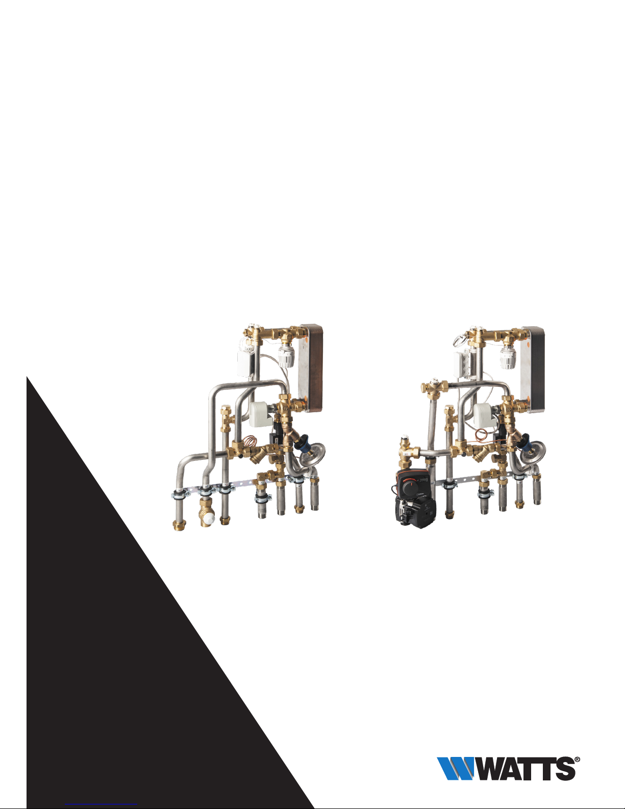
HIU 2 series
Heat Interface Unit for hygienic domestic hot water
generation and heat distribution
Installation and Operating Manual (translated
from the original operating manual)
Issued 08/2018 Revision 1
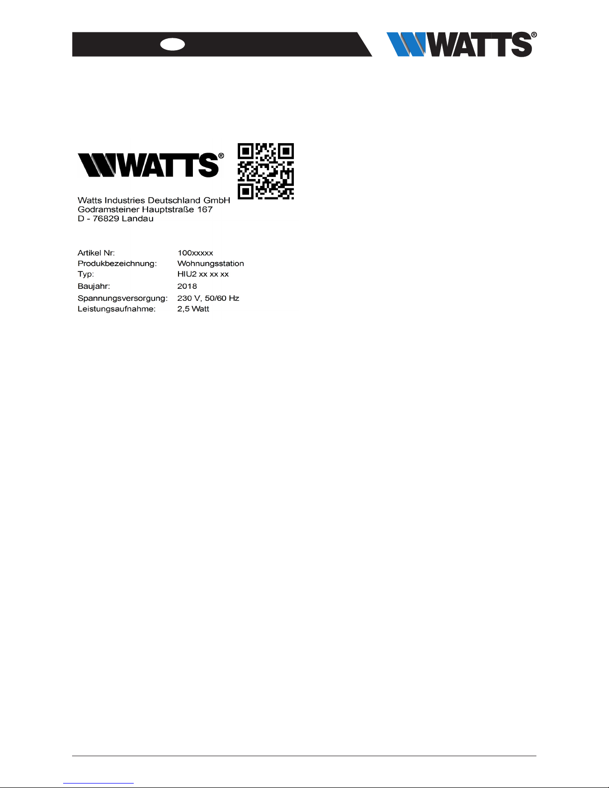
Watts Industries Deutschland GmbH
Godramsteiner Hauptstr. 167
76829 Landau
Tel.: +49 (0) 6341 96560
wide@wattswater.com
WattsWater.de

2HIU2-IM-DE-W-DE-08-2018-Rev1_DE-enUS|Art.No.10078860
EN ENGLISH
Contents
1 General information ...................................... 2
1.1 Important information about this installation and operating
manual ...........................................................................2
1.2 Product conformity .........................................................2
1.3 Product features..............................................................2
1.4 Product label...................................................................3
2 Technical data ............................................... 4
3 Safety.............................................................. 5
3.1 Depiction of safety information........................................5
3.2 Important safety information ...........................................5
3.3 Intended use ...................................................................5
3.4 Foreseeable misuse ........................................................5
3.5 Responsibilities of the operator.......................................5
3.6 Personnel groups............................................................6
3.7 Information on the operating environment.......................6
4 Structure ........................................................ 7
4.1 Hydraulic diagram ...........................................................8
4.2 HIU 2 HK.........................................................................9
4.3 HIU 2 HKM.................................................................... 10
5 Installation and commissioning .................11
5.1 Installation ..................................................................... 11
6 Power curves and diagrams ...................... 13
6.1 Power curves ................................................................ 13
6.2 Pressure loss diagrams................................................. 14
7 Maintenance ................................................ 16
7.1 Annual maintenance intervals ........................................ 16
7.2 Replacement of wear parts ........................................... 16
7.3 Cleaning the dirt trap..................................................... 17
7.4 Replacing the plate heat exchanger .............................. 17
8 Spare parts list ............................................ 18
9 Disposal........................................................ 19
9.1 Return shipment to the manufacturer............................ 19
9.2 Reporting to administrative bodies and the
manufacturer................................................................. 19
1 General information
1.1 Important information about the installa-
tion and operating manual
The operator is responsible for ensuring
adherence tothelocal lawsandregulations
(e.g. accident prevention regulations,
etc.).
Incorrect operation or operating the HIU 2
contrary to the specifications shall void all
rights to any warranty claim.
This installation and operating manual
• is a component of the HIU 2
• contains instructions and information on safe and correct
installation and commissioning of the HIU 2
• must be available to all users throughout the entire service
life of the HIU 2
• is intended for trained personnel who are familiar with the
applicable standards and provisions and, in particular, with
the relevant safety concepts and the operation and mainte-
nance of the HIU 2
• is protected by copyright and may not be altered without
the manufacturer’s permission
• may not be made accessible to unauthorized personnel,
either in original form or as a copy.
1.2 Product conformity
A Declaration of Conformity according to the Machinery
Directive 2006/42/EC has been issued for this HIU 2 product.
1.3 Product features
• Stable bracket
• Intended for installation in a surface-mounted cabinet,
flush-mounted cabinet or EPP insulation.
• All connections to the system with 1” male thread and 3/4”
male thread, and flat sealing
• Tapping temperature adjustable
• Max. draw-off capacity of DHW 12 l/min and 17 l/min
at DHW heated from 10 to 45 °C, at a primary supply
temperature of 65 °C and 200 mbar delta p.
• Very convenient controls, compact, space-saving design.
• Modular structure and suitable for connection to manifolds.
HIU2-IM-DE-W-DE-08-2018-Rev1_DE-enUS | Art. No. 10078860 3
EN
ENGLISH
1.4 Product marking
4HIU2-IM-DE-W-DE-08-2018-Rev1_DE-enUS| Art.No.10078860
EN ENGLISH
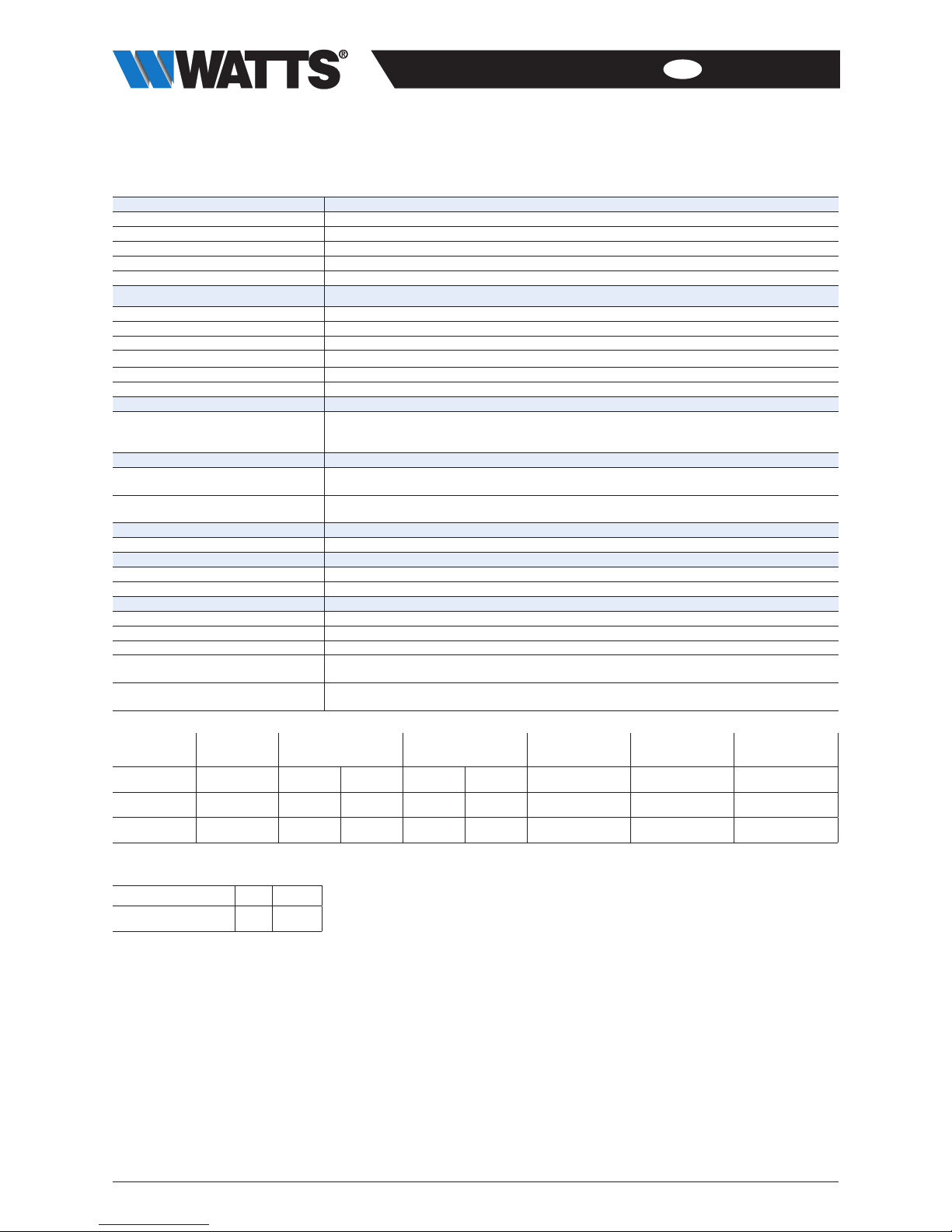
2 Technical data
Hydraulic performance data
HIU 2 HK / HIU 2 HKM
Max. operating pressure
10 bar (PN 10)
Max. ambient temperature
60 °C
Max. operating temperature
90 °C
Differential pressure
200 mbar preset. Adjustable: 100 to 300 mbar
Media
Water/water-glycol mixture as per VDI 2035/ÖNORM (Austrian standard) 5195
Actuating drive
Voltage
230 V; +10…-20 %; 50/60 Hz
Power consumption, operating
2.5 W
Power consumption, end position
<1 W
Actuating power
100 N
Protection class
IP 54
Ambient temperature
0 to 60°C
Dimensions
Width x height x depth
HK
HKM
490 X 705 X 130 mm
500 x 705 x 140 mm
Weight
Total weight excluding packaging
HK12 / HK17 / HKM12 / HKM17
approx. 13 kg / 14 kg / 16 kg / 17 kg
Total weight including packaging
HK12 / HK17 / HKM12 / HKM17
approx. 15 kg / 16 Kg / 18 Kg / 19 kg
Connections to pipe network
Heat interface unit
1” male thread and ¾” male thread, flat sealing
Meter connections
Adapter for heat meter
110 mm G ¾
Adapter for cold water meter
110 mm G ¾
Materials
Pipes
Stainless steel Ø22 & Ø27 mm
Fittings
Brass
Seals
AFM34/2 and EPDM
Plate heat exchanger
stainless steel EN 1.4404/copper (solder) | optional stainless steel/stainless steel (solder)
Refer to the corresponding data sheets for more detailed information on the media used
Circulation pump, actuator and other
components
Technical data can be found in the enclosed technical documentation.
DHW per-
formance
Primary
temperature
Secondary
temperature
Pressure loss Flow rate Flow rate
Supply Return DCW DHW Primary Primary Secondary
26 plates 33 kW 65 °C 19 °C 9 °C 48 °C 19 kPa 11.2 l/min 12.0 l/min
36 plates 40 kW 65 °C 18 °C 11 °C 45 °C 19 kPa 13.4 l/min 17.1 l / m i n
HIU 2 performance
Heat output (10K) Q= 13 kW
Heat output (20K) Q= 26 kW

HIU2-IM-DE-W-DE-08-2018-Rev1_DE-enUS | Art. No. 10078860 5
EN
ENGLISH
3 Safety
3.1 Depiction of safety information
DANGER indicates an imminent danger
that may cause serious physical injury or
death if the appropriate safety precau-
tions are not in place.
WARNING indicates a danger arising
through incorrect behavior (e.g. misuse,
disregarding notices, etc.) that may cause
serious physical injury or death.
CAUTION indicates a potentially danger-
ous situation that may cause minor or
slight injuries if the appropriate safety
precautions are not in place.
NOTICE indicates a situation that may
cause material damage if the correspond-
ing precautions are not taken.
3.2 Important safety information
• Before using the device, read this operating manual
through carefully.
• Only connect the HIU 2 to a power source that corre-
sponds to the mains voltage specified on the rating plate of
the HIU2.
• The power supply to the HIU2 must be disconnected prior
to maintenance, cleaning and repair work.
• Maintenance, cleaning and repair work may be carried out
by trained specialist personnel only.
• The HIU2 must not be used if it is damaged or if the HIU2
is no longer operating correctly. In this case, contact your
specialist dealer immediately.
• Observe the maintenance instructions and intervals.
• Protect the HIU2 from the influences of weather.
• Never use the HIU2 outdoors.
• The unit may be used only in accordance with its intend-
ed use.
3.3 Intended use
Ready-to-install compact, decentralized heat interface unit for
hygienic domestic hot water generation and heat distribution
in single-family houses and townhouse systems as well as for
use in multi-story apartment blocks.
The HIU2 is not intended to be operated by people (includ-
ing children) with physical, sensory or mental disabilities, nor
by people with insufficient experience or previous knowledge.
3.4 Foreseeable misuse
The following is considered to be foreseeable misuse:
• Operating the HIU 2 contrary to the specifications
• Improper use of the HIU2
• Modifications to the HIU2 that were not agreed with the
manufacturer
• Use of replacement or wear parts that were not approved
by the manufacturer
• Operating the HIU2 outdoors (parts and components are
not UV resistant)
• Use of prohibited media
3.5 Responsibilities of the operator
The operator must ensure that:
• the HIU2 is only used for its intended purpose
• the HIU2 is installed, operated and maintained accord-
ing to the specifications in the Installation and Operating
Manual
• the HIU2 is only operated according to local regulations
and occupational health and safety regulations
• all precautionary measures have been carried out to avoid
dangers originating from the HIU2
• all precautions for first aid and fire suppression are carried
out
• only authorized and trained users have access to the HIU2
and operate it
• users have access to this installation and operating manual
at all times

6HIU2-IM-DE-W-DE-08-2018-Rev1_DE-enUS| Art.No.10078860
EN ENGLISH
3.6 Personnel groups
Only qualified persons may install and operate the HIU 2 or
perform maintenance work.
Operator
An operator is deemed to be qualified if they have read these
operating instructions and understood the potential hazards
associated with improper behavior.
Fitter/commissioning engineer
A plumber or commissioning engineer is in a position, taking
into consideration the applicable standards, provisions, regu-
lations and laws and his/her technical training and technical
knowledge, to carry out work on the HIU 2 and to detect and
prevent potential hazards.
3.7 Information on the operating environment
Limescale deposits (from hard water) and corrosion, as well
as chemical and physical reactions, can cause damage to the
home station.
The selection of material for the plate heat exchanger (copper
or stainless steel) must be checked with reference to the water
quality (corrosion resistance).
The system planner is responsible for evaluating these
parameters and taking appropriate precautions.

HIU2-IM-DE-W-DE-08-2018-Rev1_DE-enUS | Art. No. 10078860 7
EN
ENGLISH
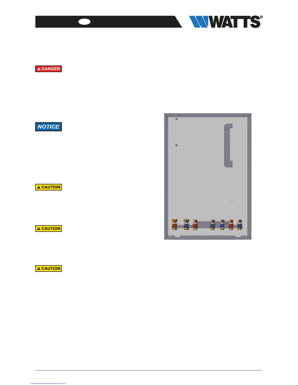
4 Structure
HIU 2 HK
10079852 HIU 2 HK 12 CU
10079891 HIU 2 HK 12 STS
10078464 HIU 2 HK 17 CU
10079893 HIU 2 HK 17 STS
• For heating and drinking water heating
• Hot water priority circuit
• Differential pressure control
• Pre-installed adapters for heat meters and cold water
meters
• Optional:
- Water hammer arrestor (Art. No. 10079166)
- Circulation set (Art. No. 10080335)
- Thermostatic circulation bridge (Art. No. 10079903)
HIU 2 HKM
10079851 HIU 2 HKM 12 CU
10079892 HIU 2 HKM 12 STS
10078463 HIU 2 HKM 17 CU
10079894 HIU 2 HKM 17 STS
• For heating and drinking water heating
• Hot water priority circuit
• Differential pressure control
• Pre-installed adapters for heat meters and cold water
meters
• Mixer module
• Optional:
- Water hammer arrestor (Art. No. 10079166)
- Circulation set (Art. No. 10080335)
- Thermostatic circulation bridge (Art. No. 10079903)

8HIU2-IM-DE-W-DE-08-2018-Rev1_DE-enUS| Art.No.10078860
EN ENGLISH
4.1 Hydraulic diagram
HIU 2 HK
Optional
:
Optional
:490mm 130mm
705mm
Optional:500mm 140mm
705mm
HIU 2 HKM

HIU2-IM-DE-W-DE-08-2018-Rev1_DE-enUS | Art. No. 10078860 9
EN
ENGLISH
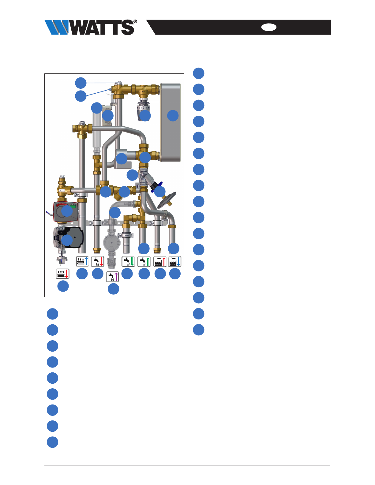
4.2 HIU 2 HK
1
2
5 6
15
4
11
18
16
14
17
10
3
19
20
7
12
21
13
22 23 24
8
9
1Vent
2Temperature sensor
3Water hammer arrestor (optional)
4Junction box
5Thermal valve
6Plate heat exchanger
7Switch valve, heating circuit/hot water
8Actuating drive
9Flow switch
10 Connection for supply temperature sensor of the
heat meter
11 Dirt trap
12 Membrane regulator/differential pressure regulator
13 Circulation set (optional)
14 Zone valve (heating circuit)
15 Adapter for cold water meter
16 Adapter for heat meter connector
17 Supply heating circuit
18 Return heating circuit
19 Domestic hot water outlet
20 Domestic water circulation inlet
21 Domestic cold water outlet
22 Domestic cold water inlet
23 Primary supply
24 Primary return
10 HIU2-IM-DE-W-DE-08-2018-Rev1_DE-enUS| Art.No.10078860
EN ENGLISH
4.3 HIU 2 HKM
1
2
5 6
15
4
11
18
16
26
17
10
3
19
20
7
12
21
13
22 23 24
25
8
9
1Vent
2Temperature sensor
3Water hammer arrestor (optional)
4Junction box
5Thermal valve
6Plate heat exchanger
7Switch valve, heating circuit/hot water
8Actuating drive
9Flow switch
10 Connection for supply temperature sensor of the
heat meter
11 Dirt trap
12 Membrane regulator/differential pressure regulator
13 Circulation set (optional)
14 -
15 Adapter for cold water meter
16 Adapter for heat meter connector
17 Supply heating circuit
18 Return heating circuit
19 Domestic hot water outlet
20 Domestic water circulation inlet
21 Domestic cold water outlet
22 Domestic cold water inlet
23 Primary supply
24 Primary return
25 Actuator including regulator
26 Heating circuit pump
HIU2-IM-DE-W-DE-08-2018-Rev1_DE-enUS | Art. No. 10078860 11
EN
ENGLISH
5 Installation and commissioning
Electricity!
Risk of death from electric shock.
• Work on parts carrying live voltage must
only be carried out by trained electricians.
• Disconnect the power supply of the sys-
tem and secure it against being switched
back on before carrying out any installa-
tion, maintenance, cleaning or repair work.
The installation and commissioning of the
HIU 2 must only be carried out by trained
personnel who have been authorized by
the manufacturer.
When installing and operating a circula-
tion system, the recognized rules of engi-
neering as well as the hygiene regulations
according to “DVGW Arbeitsblatt W551”
(German association for gas and water,
worksheet W551) must be observed.
The HIU 2 may only be installed in an
upright position.
When repairing the unit or replacing parts,
be sure to observe the specified installa-
tion positions and flow directions of the
parts being replaced.
Material damage!
Pressure shocks may occur if the stop
valve is opened quickly.
• Always open the stop valve slowly and in
a controlled way.
Bad water quality!
Hard water causes limescale deposits in
the HIU 2 and diminishes the quality of
the water.
• Measure the water hardness in the supply
system.
• Install a water softening unit from a degree
of hardness of 17° dH.
5.1 Installation
All screw fittings must be checked and tightened if nec-
essary prior to installation and commissioning.
Torque:
• ¾” screw fittings 35 Nm
• 1” screw fittings 55 Nm
Requirements
• The HIU 2 cabinet (surface-mounted or flush mounted) is
installed.
• A safety valve that cannot be shut off must be installed in
the cold water inlet to the HIU 2. In so doing, the acknowl-
edged rules of technology must be taken into account.
• The installation sequence must be observed to prevent
electrochemical corrosion of galvanized lines and fittings.
• The valves are pre-installed at the factory but must be
checked for leaks during commissioning (hydraulic pressure
test).
Recommendation: Install water filter into the cold
water inlet.
12 HIU2-IM-DE-W-DE-08-2018-Rev1_DE-enUS| Art.No.10078860
EN ENGLISH
Hot water!
Severe scalding possible.
Do not reach into the hot water when
emptying the HIU2.
Ensure that the HIU 2 has cooled down
before carrying out maintenance, clean-
ing and repair work.
Install a suitable scalding protection
device at every tapping point (for exam-
ple, safety shut-off valve or thermostat
mixer tap).
More detailed information on scalding
protection can be found in DIN 1988,
sheet 2, clause 4.2.
Danger of scalding!
To avoid scalding when tapping hot water,
appropriate scalding protection must be
provided.
Observe the recognized rules of technology
when doing so.
1. Insert the HIU 2 and connect to the connection rail.
Optional:
2. Install the water hammer arrestor, circulation set and
circulation manifold.
3. Connection to power mains (230V).
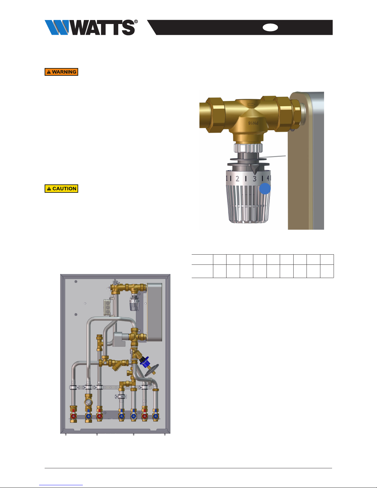
4. Set the desired tapping temperature on the thermostatic
head (X).
X
Setting, at max. flow rate with a supply temperature of
65 °C:
Scale 1I2I3I4I5
approx.
°C 34 37 41 44 48 51 55 58 63
5. Vent the primary (heating) circuit.
• Slowly open the stop valves on the heat network connec-
tors (see Chapter 4).
• Open and hold open the vent valve (see Chapter 4) until air
no longer escapes.
6. Vent the secondary circuit (domestic water).
• Slowly open all of the tapping points, one after the other,
and draw water until all lines fill up and all air has been
vented from the system.
HIU2-IM-DE-W-DE-08-2018-Rev1_DE-enUS | Art. No. 10078860 13
EN
ENGLISH
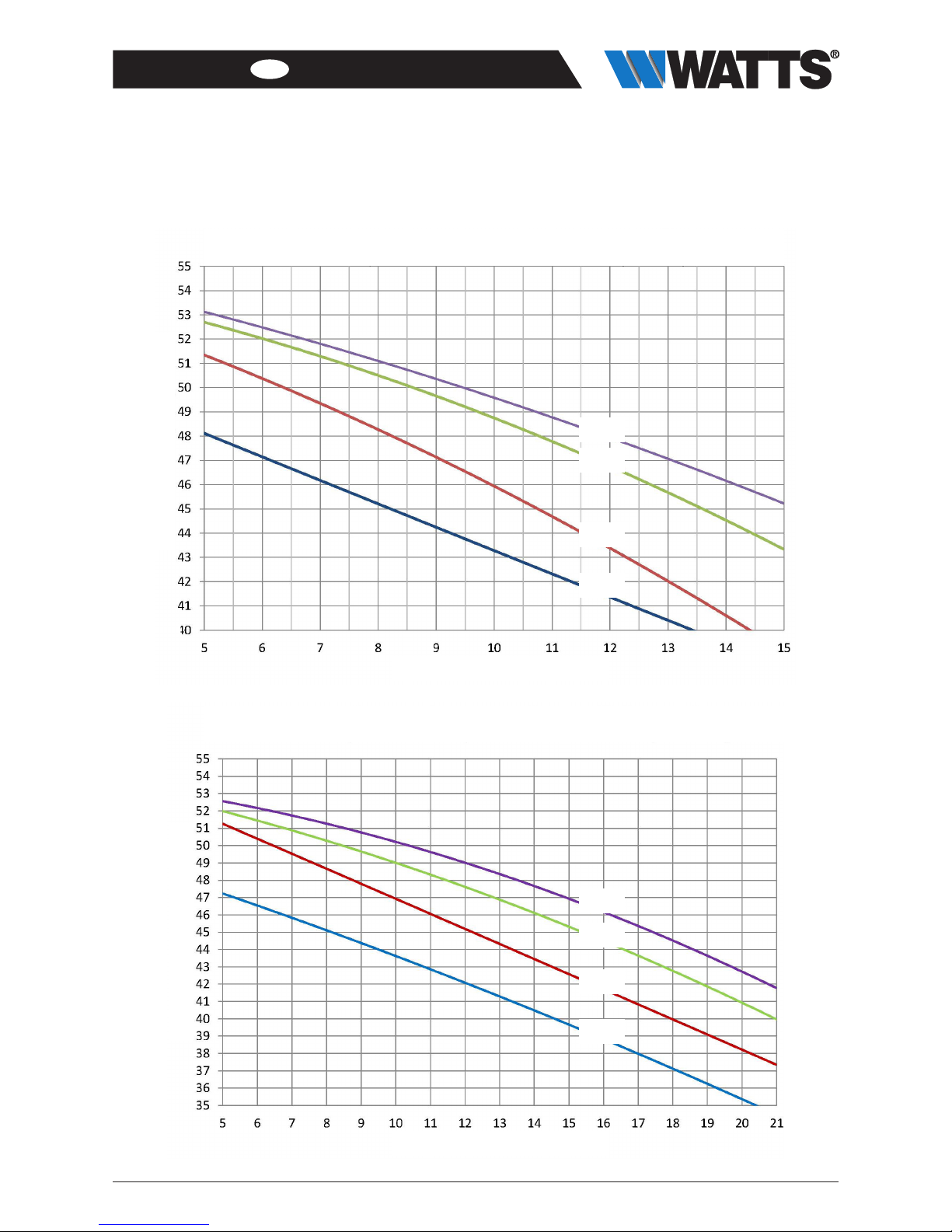
6 Power curves and diagrams
6.1 Power curves
65 °C
55 °C
60 °C
50 °C
65 °C
55 °C
60 °C
50 °C
Heat interface unit HIU 2, 26 plates, 12 l/min., 200 mbar
DHW temperature, secondary circuit, with various primary supply temperatures
Heat interface unit HIU 2, 36 plates, 17 l/min., 200 mbar
DHW temperature, secondary circuit, with various primary supply temperatures
DHW temp. [°C]
DHW temp. [°C]
tapping rate [l/min]
tapping rate [l/min]

14 HIU2-IM-DE-W-DE-08-2018-Rev1_DE-enUS| Art.No.10078860
EN ENGLISH
6.2 Pressure loss diagrams
1
10
100
1.000
10 100 1.000 10.000
Druckabfall (mbar)
Durchfluss (L/h)
Primäre Seite, Trinkwassererwärmung über Wärmetauscher
26 Platten, 12 l/min., Kvs-Wert: 1,35 m³/h (gestrichelte Linie)
36 Platten, 17 l/min., Kvs-Wert: 1,42 m³/h (durchgehende Linie)
1
10
100
1.000
10 100 1.000 10.000
Druckabfall (mbar)
Durchfluss (L/h)
Sekundäre Seite, Trinkwasser warm
26 Platten, 12 l/min. Kvs-Wert: 2,2 m³/h (gestrichelte Linie)
36 Platten, 17 l/min. Kvs-Wert: 2,5 m³/h (durchgehende Linie)
Pressure drop (mbar)
Pressure drop (mbar)
26 plates, 12 l/min., Kvs value: 1.35 m³/h (dotted line)
36 plates, 17 l/min., Kvs value: 1.42 m³/h (solid line)
Secondary circuit, domestic hot water
26 plates, 12 l/min. Kvs value: 2.2 m³/h (dotted line)
36 plates, 17 l/min. Kvs value: 2.5 m³/h (solid line)
Primary circuit, domestic hot water generated by the heat exchanger
Flow rate (l/h)
Flow rate (l/h)

HIU2-IM-DE-W-DE-08-2018-Rev1_DE-enUS | Art. No. 10078860 15
EN
ENGLISH
1
10
100
1.000
10 100 1.000 10.000
Druckabfall (mbar)
Durchfluss (L/h)
Primäre Seite, Heizungsbedarf, Wohnungsstation
HIU 2 HKM, Kvs-Wert: 1,6 m³/h (gestrichelte Linie)
HIU 2 HK, Kvs-Wert: 1,7 m³/h (durchgehende Linie)
1
10
100
1.000
10 100 1.000 10.000
Druckabfall (mbar)
Durchfluss (L/h)
Sekundäre Seite, Trinkwasser kalt
Kvs-Wert: 6,5 m³/h
Pressure drop (mbar) Pressure drop (mbar)
Primary circuit, demand heating, heat interface unit
HIU 2 HKM, Kvs value: 1.6 m³/h (dotted line)
HIU 2 HK, Kvs value: 1.7 m³/h (solid line)
Secondary circuit, domestic cold water
Kvs value: 6.5 m³/h
Flow rate (l/h)
Flow rate (l/h)

16 HIU2-IM-DE-W-DE-08-2018-Rev1_DE-enUS| Art.No.10078860
EN ENGLISH
7 Maintenance
Electricity!
Only perform maintenance work on the
HIU 2 if the voltage supply has been
disconnected.
Hot water!
Severe scalding possible.
Do not reach into the hot water when
emptying the HIU2.
Ensure that the HIU 2 has cooled down
before carrying out maintenance, clean-
ing and repair work.
Hot surfaces!
Serious burns possible.
Do not touch the tubings/pipings or com-
ponents during operation.
Ensure that the HIU 2 has cooled down
before carrying out maintenance, clean-
ing and repair work.
Wear heat-resistant safety gloves if it
is necessary to carry out work on hot
components.
The maintenance of the HIU 2 must only be
carried out by trained personnel who have
been authorized by the manufacturer.
7.1 Annual maintenance intervals
1. General visual inspection
• Check the station for leaks, annual maintenance intervals,
if necessary
1. General visual inspections
• Check the station for leaks and retighten sealing connec-
tions or replace seals, as required.
2. Functional checks
• Check that settings and operating and performance
parameters are set correctly.
• Check flow noise during operation.
• Ask users if there are any noticeable problems.
3. Ball valves
• Check that stop valves and ball valves can move freely.
4. Dirt trap
• Check and clean the dirt trap.
5. Plate heat exchanger
• Check the plate heat exchanger for limescale deposits and
clean if necessary.
6. Actions following maintenance work
• Check that all screw fittings that were unscrewed have
been retightened and retighten if necessary.
• Remove all tools, materials and other equipment used from
the working area.
• Restore the power supply.
• Slowly pressurize the HIU2 and vent it.
• Readjust the system settings if required.
7.2 Replacement of wear parts
Please note that the HIU 2 contains parts that, for technical
reasons, are subject to wear depending on the intensity of
use, even if the specified care and maintenance have been
observed.
This especially applies to mechanical parts and parts that
come into contact with water and steam, such as hoses,
seals, valves, etc.
By their nature, defects caused by wear do not constitute a
fault and are therefore not covered by the warranty or any
guarantee. Nevertheless, these defects and malfunctions
must be remedied only by trained specialist personnel.
Contact your specialist dealer for this.

HIU2-IM-DE-W-DE-08-2018-Rev1_DE-enUS | Art. No. 10078860 17
EN
ENGLISH
7.3 Cleaning the dirt trap
1. Depressurize the HIU2 (e.g. by opening the vent valve).
2. Unscrew and remove the dirt trap and clean it.
3. Replace the filter into the dirt trap after cleaning.
4. Slowly open the stop valves and vent the system.
7.4 Replacing the plate heat exchanger
1. Close all stop valves.
2. Depressurize the HIU2 (e.g. by opening the vent valve).
3. Loosen the nuts (pos. A) and remove the plate heat
exchanger.
A
A
4. Replace all seals.
5. Insert the new plate heat exchanger and tighten the nuts
(pos. A). (Refer to the “Technical data” chapter for the
torque).
6. Slowly open the stop valves.
7. Slowly pressurize the HIU2, fill and vent it.

18 HIU2-IM-DE-W-DE-08-2018-Rev1_DE-enUS| Art.No.10078860
EN ENGLISH
8 Spare parts list
Spare part Art. No:
Vent valve
1/2”
10001506
3-way valve
DN25
10001552
Dirt trap 3/4” 10017599
Balancing valve
for membrane regulator
10080350
Combination membrane
regulator
0.1-0.3 bar
10080351
2-way zone valves DN25 10046053
Actuating drive
230V 50Hz
10080349
Flow switch FS-01
3/4” female thread x 3/4”
male thread
10080352
Plate heat exchanger
XB06H-1-26, 4x3/4“, copper
brazed
10080356
Plate heat exchanger
XB06H-1-26, 4x3/4“, stain-
less-steel brazed
10080358
Plate heat exchanger
XB06H-1-36, 4x3/4“, copper
brazed
10080355
Plate heat exchanger
XB06H-1-36, 4x3/4“, stain-
less-steel brazed
10080357
Ball valve 1” red 10080359
Ball valve 1” blue 10080360
Ball valve 3/4” red 10080361
Ball valve 3/4” blue 10080362
Adapter
3/4”; 110 mm
10080363
Thermostatic head K [1-5]
incl. spiral immersion sensor
10080354
Actuator
230 V
10080348
3-way mixer
Kvs 4.0
10080053
Pump, UPM3 Auto L15-70
1”; 130 mm
10080353

HIU2-IM-DE-W-DE-08-2018-Rev1_DE-enUS | Art. No. 10078860 19
EN
ENGLISH
9 Disposal
Potential for contamination of the envi-
ronment and groundwater from improp-
er disposal!
The regulations and guidelines of the leg-
islature in the country of operation must
be complied with when disposing of com-
ponents and operating materials.
1. Ensure that all subassemblies and components are
de-energized.
2. Professionally disassemble the HIU 2 or commission a
specialist company with this task.
3. Sort the sub-assemblies and component parts into recy-
clable materials, hazardous substances and operating
materials.
4. Dispose of the sub-assemblies and components in accor-
dance with local laws and regulations or take them to be
recycled.
9.1 Return shipment to the manufacturer
Get in contact with the manufacturer if you would like to return
the HIU2 or parts of it.
9.2 Reporting to administrative bodies and
the manufacturer
Inform the manufacturer about decommissioning and disposal
of the HIU2 for statistical purposes.
10 Warranty
WATTS products are tested extensively. WATTS therefore
guarantees only the replacement or, at the sole discretion
of WATTS, the free-of-charge repair of components of the
supplied products where these, in the opinion of WATTS,
exhibit verifiable manufacturing faults. Warranty claims due
to defects or defects of title may be asserted within one (1)
year of delivery/transfer of risk. Excluded from the warran-
ty are damages attributable to normal product wear or fric-
tion and damages resulting from modifications or non-au-
thorized repairs on the products, for which WATTS rejects
all claims for compensation (direct or indirect). (For more
detailed information, please refer to our website.) In all cases,
supply is subject to the General Terms and Conditions,
which can be found at www.wattswater.de.
This manual suits for next models
2
Table of contents
Other Watts Recording Equipment manuals


