SolarEdge SMI-180 User manual

Version 1.0
SolarEdge
Safety & Monitoring
Interface (SMI-180)
Installation Guide
Disclaimers
Important Notice
Copyright © SolarEdge Inc. All rights reserved.
No part of this document may be reproduced, stored in a retrieval system or transmitted, in any form or
by any means, electronic, mechanical, photographic, magnetic or otherwise, without the prior written
permission of SolarEdge Inc.
The material furnished in this document is believed to be accurate and reliable. However, SolarEdge
assumes no responsibility for the use of this material. SolarEdge reserves the right to make changes to the
material at any time and without notice. You may refer to the SolarEdge web site (www.solaredge.com)
for the most updated version.
All company and brand products and service names are trademarks or registered trademarks of their
respective holders.
The general terms and conditions of delivery of SolarEdge shall apply.
The content of these documents is continually reviewed and amended, where necessary. However,
discrepancies cannot be excluded. No guarantee is made for the completeness of these documents.
Emission Compliance
This equipment has been tested and found to comply with the limits applied by the local regulations.
These limits are designed to provide reasonable protection against harmful interference in a residential
installation. This equipment generates, uses and can radiate radio frequency energy and, if not installed
and used in accordance with the instructions, may cause harmful interference to radio communications.
However, there is no guarantee that interference will not occur in a particular installation. If this
equipment does cause harmful interference to radio or television reception, which can be determined by
turning the equipment off and on, you are encouraged to try to correct the interference by one or more
of the following measures:
l Reorient or relocate the receiving antenna.
l Increase the separation between the equipment and the receiver.
l Connect the equipment into an outlet on a circuit different from that to which the receiver is
connected.
l Consult the dealer or an experienced radio/TV technician for help.
Changes or modifications not expressly approved by the party responsible for compliance may void the
user’s authority to operate the equipment.
SMI-Installation Guide MAN-01-00157-1.0
1
Disclaimers
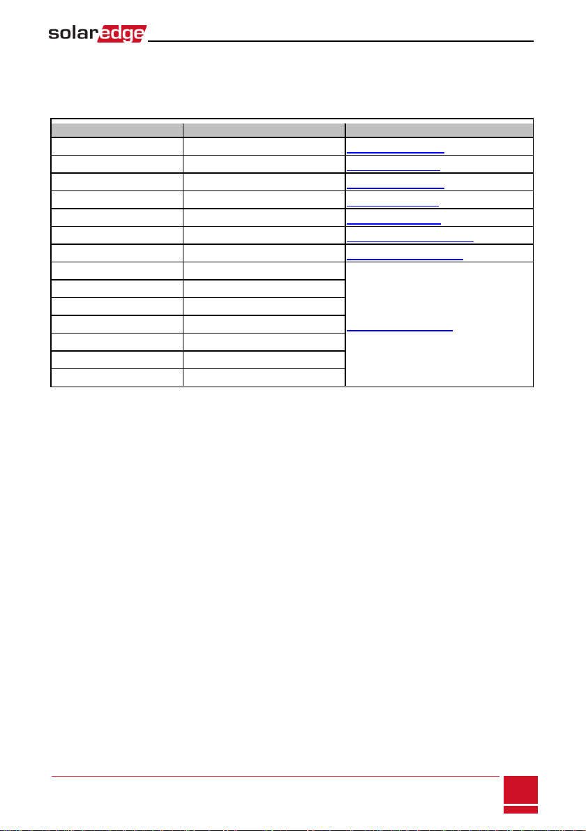
Support and Contact Information
If you have technical problems concerning our products, please contact us:
Country Phone e-Mail
Belgium 080073041 support@solaredge.be
France 0800917410 support@solaredge.fr
Germany +49 89-45459730 support@solaredge.de
Italy 800 784 824 support@solaredge.it
Japan +81.3.5530.9360 support@solaredge.jp
APAC (Asia Pacific) support-asia@solaredge.com
US & Canada 1 877 360 5292 ussupport@solaredge.com
Australia 1800149229
support@solaredge.com
Greece 00800125574
Israel +972 73 240-3118
Netherlands 08000221089
United Kingdom 0800 028 1183
Worldwide +972 73 240-3118
Fax +972 73 240-3117
Before contact, make sure to have the following information at hand:
l Inverter and power optimizer model.
l Serial number of the product in question.
l The error indicated on the inverter screen or on the SolarEdge Monitoring Portal, if there is such
an indication.
l System configuration information, including the type and number of modules connected and the
number and length of strings.
l The communication method to the SolarEdge server, if the site is connected.
Support and Contact Information
SMI-Installation Guide MAN-01-00157-1.0
2
Contents
Disclaimers 1
Important Notice 1
Emission Compliance 1
Support and Contact Information 2
Contents 3
HANDLING AND SAFETY INSTRUCTIONS 5
SAFETY SYMBOLS 5
Safety Instructions 5
Chapter 1: Introducing the Safety and Monitoring Interface (SMI) for Large Scale Installations 7
The SMI External Interfaces 8
The SMI Internal Interfaces 9
Opening and Closing the SMI Cover 9
Accessing the Internal Compartments 10
Chapter 2: SMI Installation 11
Identifying the SMI 11
Installation Workflow 11
Mounting the SMI 11
Connecting PV Strings to the SMI 15
Connecting to a DC Power Supply 18
Chapter 3: Commissioning the Safety and Monitoring Interface 20
Activating the System 20
Pairing power optimizers to the SMI 21
Verifying Proper Operation 22
Reporting and Monitoring Installation Data 23
The SolarEdge Monitoring System 23
Providing Installation Information 24
Paper Template 24
Creating a Site in the SolarEdge Monitoring Portal 24
Chapter 4: Connecting the SMI to an Inverter 25
Connecting the DC Out Cables to the SMI 25
Connecting the Inverter to the SMI 26
Verifying Proper Operation 27
Chapter 5: User Interface 28
LCD User Buttons 28
SMI Configuration – Setup Mode 29
Configuring the SMI Using the Internal LCD User Buttons 29
Configuring the SMI Using the External LCD Light Button 31
Configuration Menu Options 33
Language 33
SMI-Installation Guide MAN-01-00157-1.0
3
Contents

Communication 33
Display 35
Maintenance 35
Information 36
Status Screens - Operational Mode 36
Initial SMI Status 36
Telemetry Status 37
ID Status 37
Server Communication Status 37
IP Status 38
ZigBee Status 38
Communication Ports Status 38
Chapter 6: Setting Up Communication 40
Communication Types 40
Communication Connectors 41
Creating an Ethernet (LAN) Connection 42
Creating an RS485 Bus Connection 44
Additional Connection Options 48
Creating a Wireless ZigBee Connection 48
Creating an RS232 (UART) Connection 48
Connecting a Laptop to the SMI 48
Verifying the Connection 49
Chapter 7: Errors and Troubleshooting 50
Troubleshooting Communication - S_OK is Not Displayed 50
Error Codes 52
Chapter 8: SMI Specifications 54
Mechanical Specifications 54
Technical Specifications 56
Contents
SMI-Installation Guide MAN-01-00157-1.0
4

HANDLING AND SAFETY INSTRUCTIONS
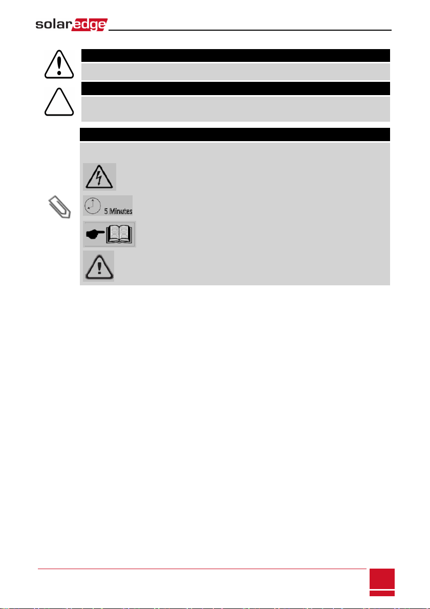
SAFETYSYMBOLS
During installation, testing and inspection adherence to all the handling and safety instructions is
mandatory.
WARNING!
Denotes a hazard. It calls attention to a procedure that, if not correctly performed or adhered to,
could result in injury or loss of life. Do not proceed beyond a warning note until the indicated
conditions are fully understood and met.
CAUTION!
Denotes a hazard. It calls attention to a procedure that, if not correctly performed or adhered to,
could result in damage or destruction of the product. Do not proceed beyond a caution sign
until the indicated conditions are fully understood and met.
NOTE!
Denotes additional information about the current subject.
IMPORTANT SAFETY FEATURE
Denotes information about safety issues.
Safety Instructions
WARNING!
Do not remove the SMI cover before five minutes have elapsed after disconnecting all sources of
power.
WARNING!
Before operating the SMI, ensure that the has been grounded properly.
WARNING!
Opening the SMI and repairing or testing under power must be performed only by qualified service
personnel familiar with the SMI.
WARNING!
The SMI is designed to work in conjunction with non-SolarEdge inverters and with SolarEdge power
optimizers equipped with the IndOp™ technology. It will NOT work with the SolarEdge fixed string
voltage mode. Therefore, string lengths and system design must comply with the inverter design
guidelines. SolarEdge extended string lengths are not applicable. Designing outside of the inverter
design rules may result in permanent damage to the SMI.
SMI-Installation Guide MAN-01-00157-1.0
5
HANDLING AND SAFETY INSTRUCTIONS
WARNING!
If the photovoltaic array is exposed to light, it supplies DC voltage to the power optimizers.
CAUTION!
This unit must be operated under the specified operating conditions as described in the
Specifications chapter.
NOTE
The following warning symbols appear on the SMI warning label:
Risk of electric shock
Risk of electric shock from energy stored in the capacitor. Do not remove
cover until 5 minutes after disconnecting all sources of supply.
Refer to the product documentation
General hazard
HANDLING AND SAFETY INSTRUCTIONS
SMI-Installation Guide MAN-01-00157-1.0
6
Chapter 1: Introducing the Safety and
Monitoring Interface (SMI) for Large Scale
Installations
When connecting SolarEdge power optimizers to a non-SolarEdge inverter, the SolarEdge safety and
monitoring interface for large scale installations (SMI) enables the following features:
1. Safety functions of the power optimizers
2. Communication of the module-level data sent from the power optimizers to the SolarEdge
monitoring portal.
SolarEdge offers also the monitoring interface (MI) , which includes only the second feature above.
The SMI supports the SolarEdge optimizer SafeDC™ feature. The SafeDC™ mechanism automatically shuts
down module voltage whenever the grid power is shut down, thus providing greater safety during
installation, maintenance and firefighting.
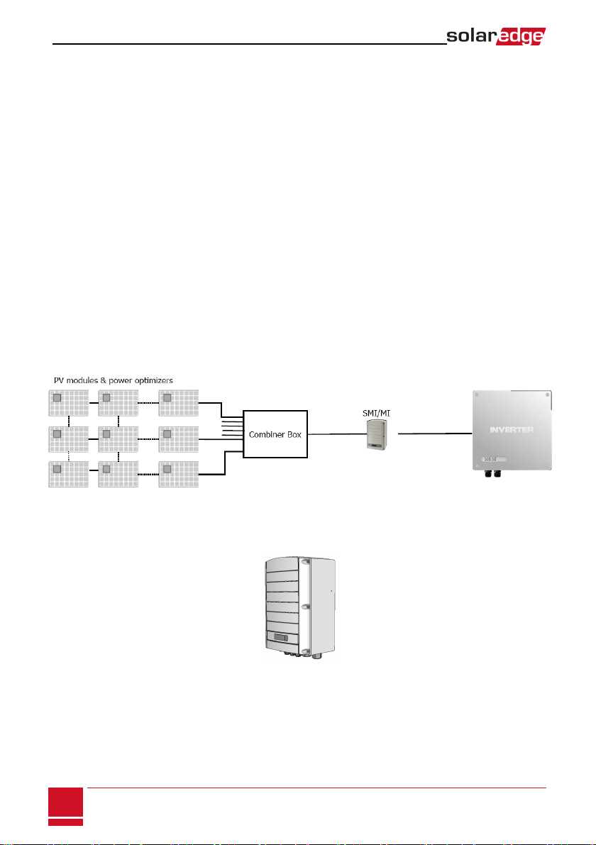
The SMI is installed between the SolarEdge power optimizers and a non-SolarEdge inverter, and is
compatible with any on-grid inverter.
Figure 1: The SolarEdge safety and monitoring interface for large scale installations
(SMI) connected in a PV system
Figure 2: The SolarEdge safety and monitoring interface (SMI) for large scale
installations
SMI-Installation Guide MAN-01-00157-1.0
7
Chapter 1: Introducing the Safety and Monitoring Interface (SMI) for Large Scale
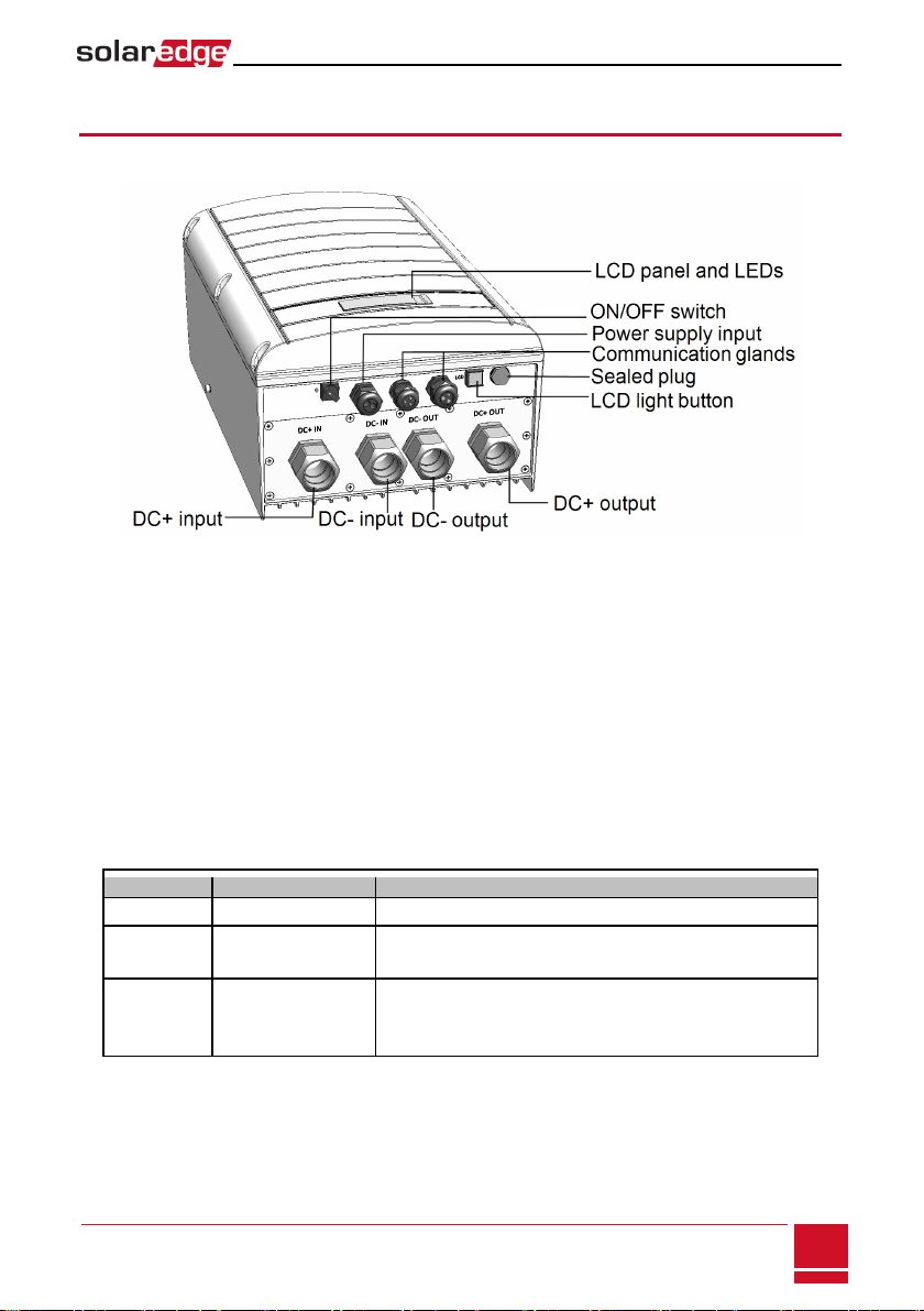
The SMI External Interfaces
The following shows the SMI connectors and interfaces:
Figure 3: SMI interfaces
l ON/OFF Switch: Turning this switch ON (1) starts the operation of the power optimizers. Turning
it OFF (0) reduces the power optimizer voltage to a low and safe value. In the MI this functionality
is disabled.
l LCD Light Button: Pressing this button lights up the LCD for 30 seconds. In addition, you can
press this button to access configuration menu options, as described in Configuring the SMI Using
the External LCD Light Button on page 31.
l Two Communication Glands, for connection of communication options. Refer to Setting Up
Communication on page 40.
l Power supply input: Used to connect the SMI to an auxiliary power supply unit.
l LCD panel: displays SMI information and configuration parameters
l LCD LEDs: Three LEDs indicate the following SMI statuses:
Color Description Functionality
Green Power OK Indicates whether the SMI is connected to power.
Yellow Module
Communication
Blinking when monitoring information is received from a power
optimizer.
Red Fault
Indicates that there is an error. Refer to Errors and
Troubleshooting on page 50 for more information. In addition, this
LED blinks while the SMI is being shut down.
All LEDs are on while the SMI is being configured.
Chapter 1: Introducing the Safety and Monitoring Interface (SMI) for Large Scale
SMI-Installation Guide MAN-01-00157-1.0
8
The SMI Internal Interfaces
As part of the installation and configuration process, accessing the internal components of the SMI may
be required. This involves removing the cover of the SMI.
Opening and Closing the SMI Cover
To remove the SMI cover:
1. Turn the ON/OFF switch to OFF.
2. Disconnect the power to the SMI:
a. Turn OFF the inverter
b. Turn OFF the PSU. Wait 5 minutes for the inverter and SMI capacitors to discharge.
3. Open the cover’s six Allen screws and carefully remove the cover.
CAUTION!
When removing the cover, make sure not to damage internal components. SolarEdge will not be
held responsible for any components damaged as a result of incautious cover removal.
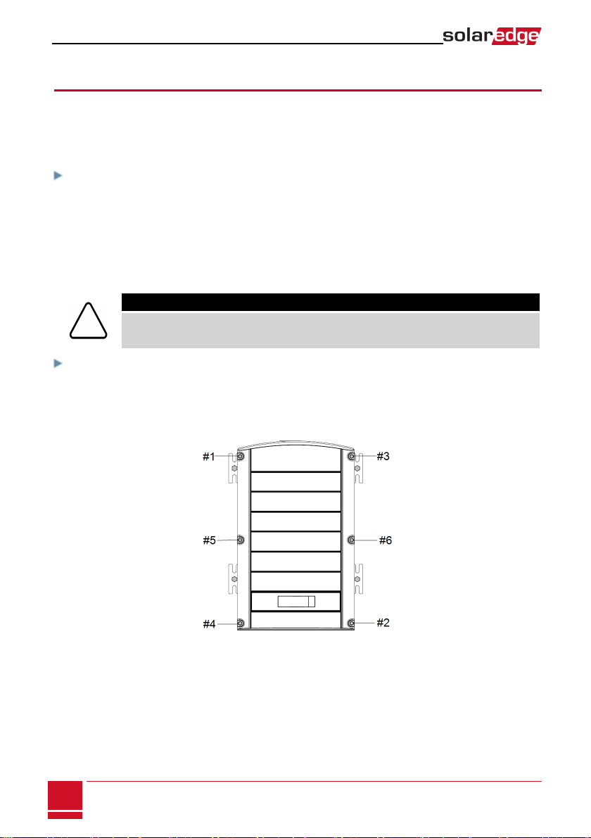
To close the SMI cover:
Attach the cover and secure it by tightening the screws with a torque of 4.0 N*m/ 2.9 lb*ft. For proper
sealing, first tighten the corner screws and then the two central screws. The following figure illustrates the
recommended order:
Figure 4: Tightening order of the screws
SMI-Installation Guide MAN-01-00157-1.0
9
The SMI Internal Interfaces
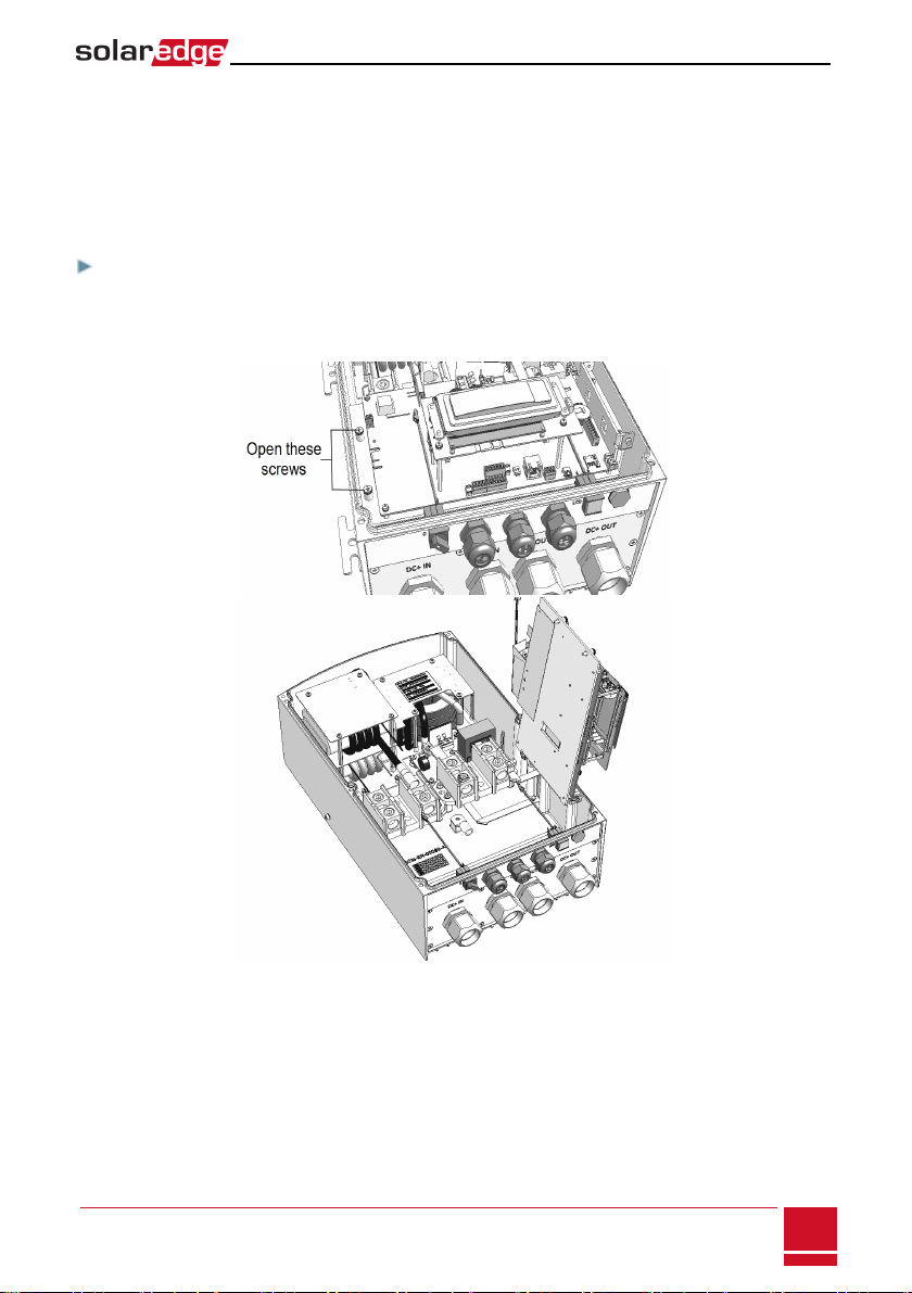
Accessing the Internal Compartments
The SMI is divided into two compartments by a plate. The top compartment on the plate includes the
communication board, the LCD screen and user buttons, the power supply connector and
communication connectors. The lower compartment includes the DC input and output connections.
The lower compartment is accessed by lifting the plate which is hinged to the SMI enclosure.
To access the lower compartment:
1. Loosen the two screws on the left side of the internal plate.
2. Carefully lift the internal plate.
Figure 5: Accessing the SMI lower compartment
Chapter 1: Introducing the Safety and Monitoring Interface (SMI) for Large Scale
SMI-Installation Guide MAN-01-00157-1.0
10
Chapter 2: SMI Installation
CAUTION!
Do not rest the connectors at the bottom of the SMI on the ground, as it may damage them. To rest
the SMI on the ground, lay it on its back, front or side.
Identifying the SMI
Refer to the sticker on the SMI that specifies its Serial Number and its Electrical Ratings. Provide the serial
number when contacting SolarEdge support. The serial number is also required when opening a new site
in the SolarEdge monitoring portal.
Installation Workflow
1. Mounting the SMI on page 11
2. Accessing the Internal Compartments on page 10
3. Connecting PV Strings to the SMI on page 15
4. Connecting to a DC Power Supply on page 18
5. Pairing power optimizers to the SMI on page 21
6. Connecting the SMI to an Inverter on page 25
7. Setting Up Communication on page 40
Mounting the SMI
This chapter describes how to mount the SMI. At this stage, power optimizers are already installed and
connected in strings. For more information on power optimizer installation, refer to the IndOP™ power
optimizers installation guide available on the SolarEdge website at
http://www.solaredge.com/files/pdfs/products/power-optimizers/se_power_optimizers_installation_
guide_indop.pdf.
The SMI can be mounted either vertically or horizontally. Each of these installation options is described
below. The SMI is supplied with two brackets pre-assembled for vertical mounting. When choosing the
horizontal mounting option, remove these brackets and use the four floor anchoring brackets supplied in
the package.
To Mount the SMI vertically:
1. Determine the SMI mounting location, on a wall or pole, as follows:
l To allow proper heat dissipation, maintain 2'' / 5 cm minimum clearance areas between the SMI
and other objects.
l Make sure the mounting surface or structure can support the weight of the SMI.
SMI-Installation Guide MAN-01-00157-1.0
11
Chapter 2: SMI Installation
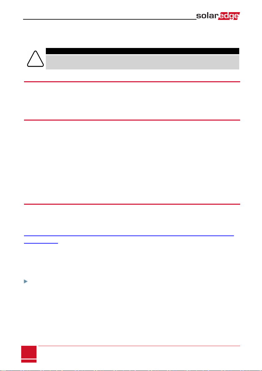
2. Position the mounting bracket against the wall and mark the drilling hole locations. Ensure that the
flat side of the bracket is at the bottom.
Figure 6: Wall mounting bracket
3. Use at least two bracket holes. Additional holes can be used to fix the bracket.Determine which and
how many holes to use according to mounting surface type and material.
4. Drill the holes and mount the bracket. Verify that the bracket is firmly attached to the mounting
surface.
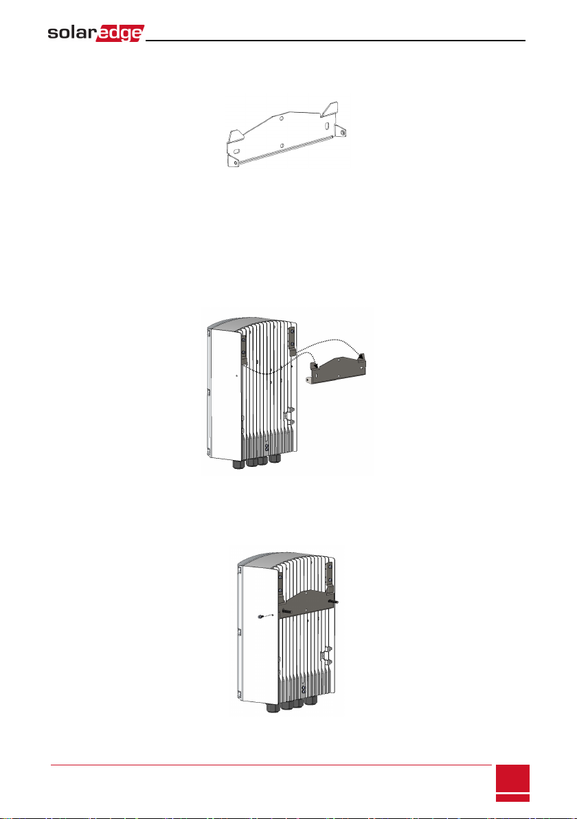
5. Hang the SMI on the bracket: Align the two assembled brackets on the SMI enclosure with the two
triangular protrusions of the mounting bracket, and lower the SMI until it rests on the bracket.
Figure 7: Hanging the SMI on the bracket
6. Insert the two supplied screws through the outer heat sink fin on both sides of the and into the
bracket. Tighten the screws with a torque of 4.0 N*m / 2.9 lb.*ft.
Figure 8: Inserting the bracket screw
Chapter 2: SMI Installation
SMI-Installation Guide MAN-01-00157-1.0
12
To mount the SMI horizontally:
1. Determine the SMI mounting location, on a rail or on the floor, as follows:
l To allow proper heat dissipation, maintain 2'' / 5 cm minimum clearance areas between the
SMI and other objects.
l Make sure the mounting surface or structure can support the weight of the SMI.
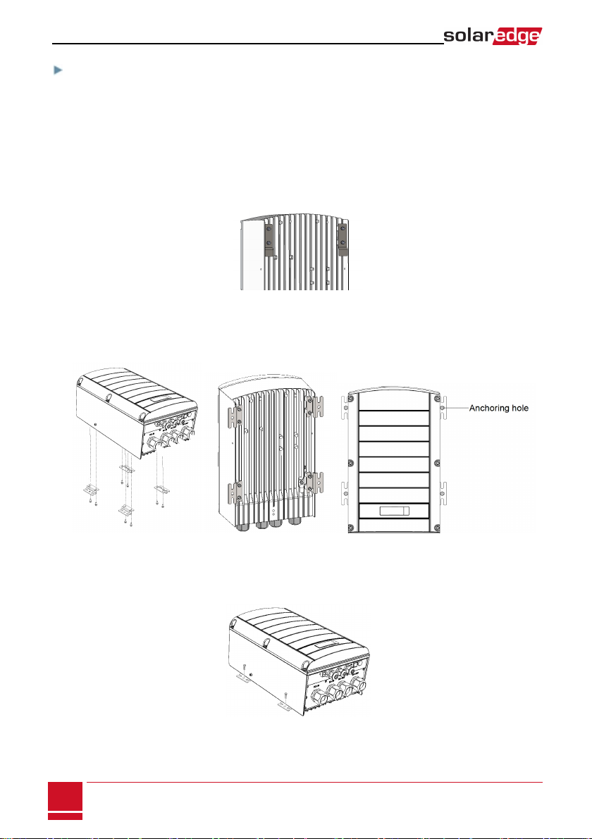
2. Remove the two vertical mounting brackets that are attached to the unit and used for vertical
mounting.
Figure 9: Vertical mounting brackets
3. Assemble the four horizontal mounting brackets (supplied in the package) to the SMI rear side. Make
sure the floor anchoring holes are facing out.
Figure 10: Horizontal mounting brackets
4. Mount the unit on the rail or structure: Use 5/16" screws or bolts (8.0 mm diameter) for anchoring to
the surface.
Figure 11: Horizontal anchoring screws
SMI-Installation Guide MAN-01-00157-1.0
13
Mounting the SMI
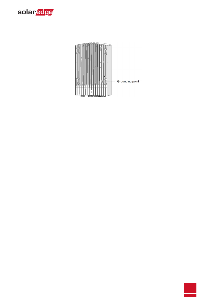
Functional earthling is required to enable the over-voltage protection. To earth the SMI, connect a
grounding cable to the grounding location at the rear of the SMI. The grounding cable must be at least
1.5mm2. You may use a cable of up to 50mm2.
Figure 12: Grounding point
Chapter 2: SMI Installation
SMI-Installation Guide MAN-01-00157-1.0
14
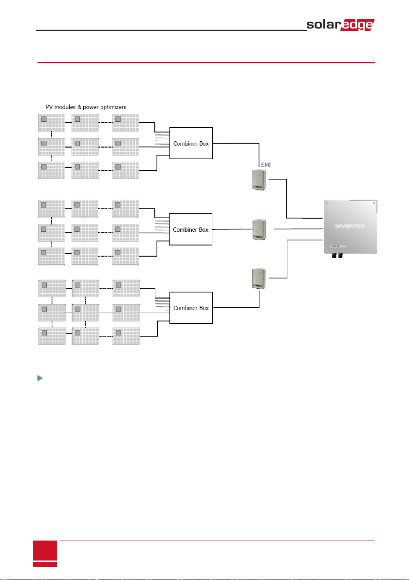
Connecting PV Strings to the SMI
The following procedure describes how to connect the DC cables from the power optimizer strings to the
SMI. A typical installation has up to 18 strings connected to an SMI through a combiner box.
Figure 13: String connection
To determine how many strings can be connected to the SMI:
Verify that the cumulative short circuit current (Isc) of all parallel-connected strings is below:
l The rated maximum input current of the inverter
l The rated maximum input current of the SMI
SMI-Installation Guide MAN-01-00157-1.0
15
Connecting PV Strings to the SMI

To connect DC strings to the SMI:
1. Open the lower compartment of the SMI as described in Accessing the Internal Compartments on page 10.
Figure 14: Connection area
2. Use an Allen key to loosen the 5/16” screws of the SMI DC power distribution blocks.
3. Remove the seal from the glands labeled DC+IN/DC-IN.
Figure 15: SMI - bottom view
4. If the cables from the combiner box are 18-25 mm in diameter, insert the wires through the opening.
If the cables are less than 18 mm in diameter, replace the rubber seals in the gland with the rubber
seals supplied in the SMI package, and insert the wires through the opening.
5. Connect the cables to the DC+ and DC- input connectors.
Chapter 2: SMI Installation
SMI-Installation Guide MAN-01-00157-1.0
16
6. Fasten the Allen screws of the power distribution blocks. Apply a torque of 30 N*m / 22 lb.*ft
Figure 16: DC IN cables connected
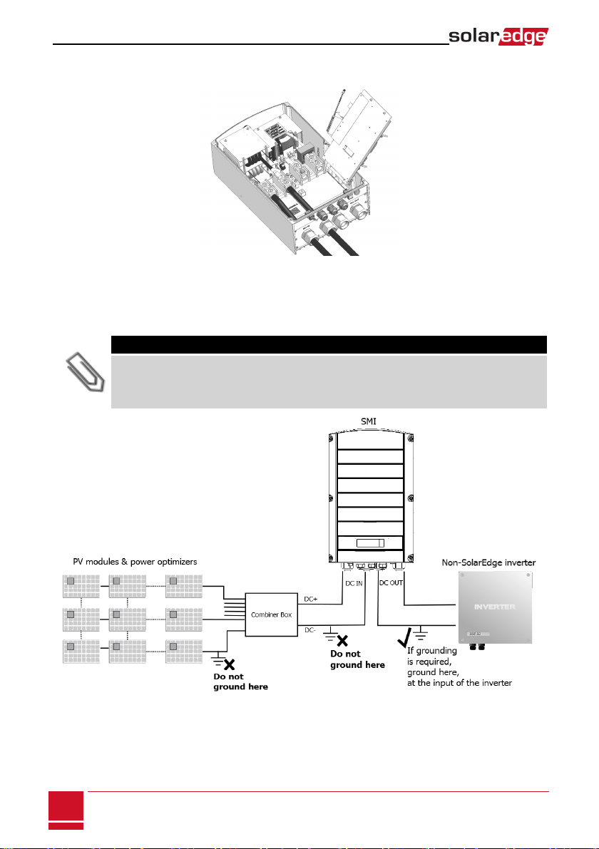
If grounding of the DC wires is required, refer to the following figure that demonstrates proper and
improper grounding locations (marked 3and ×).
NOTE
When connecting the SMI to a grounded array, the grounding must not be between the SMI and the
power optimizers. All grounding should be at the inverter or between the SMI output and the inverter.
The SMI allows both positive and negative grounding.
Figure 17: Example - Grounding locations
SMI-Installation Guide MAN-01-00157-1.0
17
Connecting PV Strings to the SMI

Connecting to a DC Power Supply
The SMI is powered from a separate DC power supply unit (PSU, not provided by SolarEdge). Use a PSU
with 48V nominal voltage. The input of the SMI can be connected to voltages 30-55 VDC, and each SMI will
consume 12W.
CAUTION!
The PSU must be limited or fused to 50A .
Up to 10 SMIs can connect to a single PSU.
Refer to the following table for selecting the PSU wiring and the DC wiring, depending on the number of
SMIs connected to the same PSU:
No. of SMIs AWG/mm2Cable length between PSU and the
farthest SMI (m/ft)
10 14 / 2.08 570 / 1870
18 / 0.82 220 / 722
20 / 0.52 140 / 459
8 14 / 2.08 720 / 2362
18 / 0.82 280 / 918
20 / 0.52 180 / 590
6 14 / 2.08 960 / 3150
18 / 0.82 380 / 1246
20 / 0.52 240 / 787
4 14 / 2.08 1440 / 4724
18 / 0.82 570 / 1870
20 / 0.52 360 / 1181
2 14 / 2.08 2890 / 9481
18 / 0.82 1140 / 3740
20 / 0.52 720 / 2362
Chapter 2: SMI Installation
SMI-Installation Guide MAN-01-00157-1.0
18

Figure 18: Power supply connection
To connect the power supply:
1. Strip 0.32''/ 8 mm of the power cable wire insulation.
2. Remove the seal from one of the openings in gland #3 and insert the wires through the opening. If the
cable is not thick enough to seal the opening, use a free opening in gland #1 or #2.
Figure 19: The upper connection panel of the SMI
3. Loosen the screws of the pins on the leftmost and rightmost of the 4-pin connector (supplied in the
SMI package). If connecting more than one SMI, loosen all four screws.
4. Connect the (-) wire(s) to the left side of the connector.
5. Connect the (+) wire(s) to the right side of the connector.
6. Push the connector into the 4-pin terminal block on the communication board.
Figure 20: 4-pin connector and power supply (Aux. power) terminal block
SMI-Installation Guide MAN-01-00157-1.0
19
Connecting to a DC Power Supply
Other manuals for SMI-180
1
Table of contents
Other SolarEdge Recording Equipment manuals


Popular Recording Equipment manuals by other brands


Waves
Waves Hear Back PRO SoundGrid Card user guide

360 Systems
360 Systems TSS-1080p Operation manual

PRESONUS
PRESONUS Firestudio Project user manual

Leviton
Leviton Plug-In Serial Interface Module RZCP installation instructions

Tascam
Tascam DR-40 Reference manual

Honeywell
Honeywell CENTRA LINE IF-LON Mounting instructions