manuals.online logo
Brands
  1. Home
  2. •
  3. Brands
  4. •
  5. Watts
  6. •
  7. Thermostat
  8. •
  9. Watts DualTemp P-3285 User manual

Watts DualTemp P-3285 User manual

Other Watts Thermostat manuals

Watts Vision BT-D03 RF User manual

Watts

Watts Vision BT-D03 RF User manual

Watts tekmar 518 User manual

Watts

Watts tekmar 518 User manual

Watts Radiant 519 User manual

Watts

Watts Radiant 519 User manual

Watts FloorStat 500650-120CS User manual

Watts

Watts FloorStat 500650-120CS User manual

Watts Vision BT-D03 RF User manual

Watts

Watts Vision BT-D03 RF User manual

Watts FloorStat 500650-120CS User manual

Watts

Watts FloorStat 500650-120CS User manual

Watts Tekmar WiFi Thermostat 561 User manual

Watts

Watts Tekmar WiFi Thermostat 561 User manual

Watts Tekmar 563 User manual

Watts

Watts Tekmar 563 User manual

Watts tekmar Invita Installation instructions

Watts

Watts tekmar Invita Installation instructions

Watts WFHT 041 User manual

Watts

Watts WFHT 041 User manual

Watts Milux Star User manual

Watts

Watts Milux Star User manual

Watts MILUX RF User manual

Watts

Watts MILUX RF User manual

Watts BT-DRF-02 User manual

Watts

Watts BT-DRF-02 User manual

Watts RCL-HC User manual

Watts

Watts RCL-HC User manual

Watts Wattstemp 740 User manual

Watts

Watts Wattstemp 740 User manual

Watts Tekmar WiFi Thermostat 561 User manual

Watts

Watts Tekmar WiFi Thermostat 561 User manual

Watts BT DPRF-01 User manual

Watts

Watts BT DPRF-01 User manual

Watts BT-TH02 RF User manual

Watts

Watts BT-TH02 RF User manual

Watts WFHT 041 User manual

Watts

Watts WFHT 041 User manual

Watts tekmar 562 User manual

Watts

Watts tekmar 562 User manual

Watts 148WM User manual

Watts

Watts 148WM User manual

Watts FloorStat 500650-120CS User manual

Watts

Watts FloorStat 500650-120CS User manual

Watts tekmar 560 User manual

Watts

Watts tekmar 560 User manual

Watts WTC-ES User manual

Watts

Watts WTC-ES User manual

Popular Thermostat manuals by other brands

Full Gauge TIC-17C product manual

Full Gauge

Full Gauge TIC-17C product manual

Imit Chronomix S manual

Imit

Imit Chronomix S manual

ChiliTec ST-35 ana instruction manual

ChiliTec

ChiliTec ST-35 ana instruction manual

Salus VS05 Installer's/user's manual

Salus

Salus VS05 Installer's/user's manual

Azel D-500 user guide

Azel

Azel D-500 user guide

Honeywell Chronotherm III owner's manual

Honeywell

Honeywell Chronotherm III owner's manual

Charmeg MP-R user manual

Charmeg

Charmeg MP-R user manual

dixell WING XW40LS Installing and operating instructions

dixell

dixell WING XW40LS Installing and operating instructions

Network Thermostat NetX X7C-WIFI Installation and programming manual

Network Thermostat

Network Thermostat NetX X7C-WIFI Installation and programming manual

Radio Thermostat CT80 Operation guide

Radio Thermostat

Radio Thermostat CT80 Operation guide

HAI Omnistat RC-120 installation manual

HAI

HAI Omnistat RC-120 installation manual

Lennox iComfort E30 Installation and setup guide

Lennox

Lennox iComfort E30 Installation and setup guide

Lux Products PSD011Ba Installation and operating instructions

Lux Products

Lux Products PSD011Ba Installation and operating instructions

Computherm Q20 operating instructions

Computherm

Computherm Q20 operating instructions

Heatmiser neoStat user manual

Heatmiser

Heatmiser neoStat user manual

Mars HEAT CONTROLLER IR Wireless Thermostat user manual

Mars

Mars HEAT CONTROLLER IR Wireless Thermostat user manual

LUX LP0511D user manual

LUX

LUX LP0511D user manual

Saswell SAS920XWHB-7-S-RF User manual and warranty card

Saswell

Saswell SAS920XWHB-7-S-RF User manual and warranty card

manuals.online logo
manuals.online logoBrands
  • About & Mission
  • Contact us
  • Privacy Policy
  • Terms and Conditions

Copyright 2025 Manuals.Online. All Rights Reserved.

Dimensions: 3-3/8" x 3-3/8"
The Watts Radiant DualTemp thermostat has the ability to sense
the temperature of the air, floor or a combination of air and floor.
Each DualTemp comes with an internal air sensor. An OPTIONAL
external 10k sensor which allows detection of floor temperatures may
be ordered separately. The external sensor does not have to be used if
the DualTemp is to detect air temperatures only.
For Residential and Commercial Applications
08-04
Job Name ––––––––––––––––––––––––––––––––––––––––––– Contractor
––––––––––––––––––––––––––––––––––––––––––––
Job Location ––––––––––––––––––––––––––––––––––––––––– Approval
–––––––––––––––––––––––––––––––––––––––––––––
Engineer ––––––––––––––––––––––––––––––––––––––––––––– Contractor’s P.O. No. –––––––––––––––––––––––––––––––––––
Approval ––––––––––––––––––––––––––––––––––––––––––––– Representative
––––––––––––––––––––––––––––––––––––––––
Watts product specifications in U.S. customary units and metric are approximate and are provided for reference only. For precise measurements,
please contact Watts Technical Service. Watts reserves the right to change or modify product design, construction, specifications, or materials
without prior notice and without incurring any obligation to make such changes and modifications on Watts products previously or subsequently sold.
4 4 2 2 6 7 NTC A/B
Wall Anchor Point
Power Connections
Electrical Access
Optional Sensor Connections
Optional Floor Sensor
Screw Cover
Cover Screw
+/- Adjustment and
Temperature Set Buttons
Mounting Screw
Base
Digital Display
Cover
DualTemp Digital Thermostat
DESCRIPTION PROPERTY
Operation Voltage 24V
Contact 10A, 230Vac Relay
Sensor NTC 10K Thermistor
Static Differential 1°F
Proportional 10 minutes for 3.5°F
Built-in manual setback 7°F
Air Temp Range 41- 99°F
Floor Temp Range 41- 99°F
°C °F
10 50.0
15 59.0
20 68.0
25 77.0
30 86.0
35 95.0
Installation & Operation
To mount the thermostat remove the thermostat cover by removing the
white Screw Cover (located in the center of the thermostat cover) and
the Cover Screw. Secure the Base Unit to the wall. Be sure to feed the
electrical wiring (18-3 or 18-4) through the provided slot in the Base Unit
and connect to appropriate terminal block(s). Replace the Cover, Cover
Screw and Screw Cover.
If floor sensing is desired, make sure the floor sensor is connected to
the corresponding floor sensor terminals (labeled NTC, the first two
terminals on the right terminal block). It may be necessary to adjust the
J6 setting. See wiring diagrams for details.
Changing Values
To enter the pa rameter menu, press and hold the OK button for 5 seconds.
Use the +/- keys to select the installation parameter to be adjusted. Press OK to
toggle the parameter setting or to edit its value. When the value begins to blink,
use the +/- keys to adjust its value. Press OK to select the adjusted value. Use the
+/- keys to select the next parameter and repeat.
Toggle to “End” and press OK to exit the installation parameter menu.
DualTemp Thermostat with opitonal floor sensor.
Product Options
Qty Description Model # Order #
DualTemp, 24V Digital, Air/Floor P-3285 81009395
Floor Sensor, 10K 500802 81000505
08-07 Effective Date 04/08 © Watts Radiant, 2008
USA: 4500 East Progress Place, Springfield, MO 65803; www.wattsradiant.com
Canada: 5435 North Service Rd., Burlington, ONT. L7L 5H7; www.wattscanada.ca
CONTROL SETTINGS AND PARAMETERS
J0: °C/°F Temperature display section.
J1: Hot/Cold regulation mode. Select Hot for Heating, Cold for cooling.
Hot: opens actuator when temperature rises above setpoint.
Cold: closes actuator when temperature closes below setpoint.
Cy: Proportional Integral regulation time cycle, value in minutes
(default: 15 minute cycle).
This setting adjusts how frequently the control monitors the sensor
readings. Lower mass systems (frame floor aplications) can loose
heat faster than high mass systems (slabs) and may require a faster
cycle time.
bp: Proportional Integral regulation band amplitude value in degrees °C/°F
(default: 2.0°C/3.6°F).
J4: NO/NC Normally Open or Normally Close actuator selection.
NC: If using an isolation relay and/or a relay box.
NO: if connecting to a Watts Zone Valve control.
J5: Select PMP (Pump Maintenance Program) to perform a 1 minute
exercise everyday.
Use this setting to allow the thermostat to cylce the circulator for
1 minute every day. This setting helps maintain lubircation during
no-heat periods.
J6: Air: Air (room) setpoint. Displays air temperature with floor low (FL) and
high (FH) limits.
Flr: Floor (external sensor) setpoint. Displays floor temperature without
floor low/high limits. Air temperature is not a control boundary.
J7: rEG (proportional Integral) or HYs (0.3°C Hysteresis) regulation
type selection.
rEG is prefered setting for use with radiant applications.
HYs is prefered setting for use with forced air or other
covection systems.
Cp: Proportional Integral regulation temperature compensation value in °C/°F
(default: 2.0°C/3.6°F).
Adjusts the calibration between the displayed temperature reading
and the calibrated temperature reading. Do not adjust this value
unless necessary.
Ao: Air Sensor offset adjustment (default: no offset), display measure air sensor
value.
Adjust the display reading to match the air sensor reading.
Fo: Floor sensor offset adjustment (default: no offset), display measure floor
sensor value.
Adjust the display reading to match the floor sensor reading.
FL: Floor temperature LOW limitation (default: 5°C/41°F), effective only if floor
sensor present and set J6 to Air.
This setting keeps the floor from dropping below the
designated temperature.
FH: Floor temperature HIGH limitation (default: 28°C/82°F), effective only if floor
sensor present and set J6 to Air.
This setting keeps the floor from rising above the
designated temperature.
CLr: Press OK to reset to factory defaults.
End: Press OK to exit installation parameters.
Comfort Operating Mode (Sun): Press +/- button(s) to adjust the
desired setpoint.
Night Setback Mode (Moon): Sets the operating temperature to a lower point.
Use the +/- button(s) to adjust the setback temperature.
Timer (Clock): Thermostat can be tied into an external timer to control system
operation.
Blinking sun indicates system is in Comfort Mode.
Blinking moon indicated system is in Setback Mode.
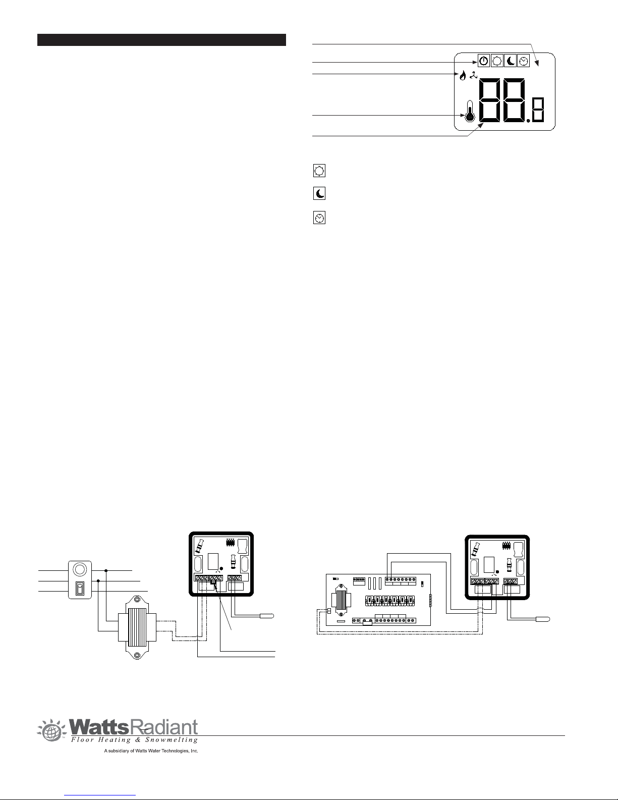
Optional
Floor
Sensor
Digital DualTemp with Transformer and Relay
Transformer
Black
Green
White
Green
White
Black
Fusetron
24Vac Hot
Neutral
To Relay Coil "A" Side
To Relay Coil "B" Side
4 4 2 2 6 7 NTC A/B
Requires jumper between 2 & 6
Optional
Floor
Sensor
Digital DualTemp with Third Party Relay Box
To "T1" Terminal
1 2 3
4
Transformer
24VAC
X
X
ZONE 3ZONE 1ZONE 2 ZONE
4
POWER
INPUT
ZONE 2
ZR
ZC
ZONE 1 ZONE 3 ZONE
4
To "T2" Terminal
4 4 2 2 6 7 NTC A/B
R
C
J1
°F
°C
Operating Mode Menu
(power, comfort, set-back, timer)
Heat/Cool Operation Indicator
Indicates Display is Showing
Current Temperature
Shows Measured or Set Temperature
Operation Parameter (see chart for details)
Note: Do not apply power to the relay ("dry" contact) terminals on the
DualTemp. Doing so will cause damage to the thermostat.
Do not apply line voltage (120 volt) power to thermostat. Applying anything other
than the recommended 24 volt power will damamge the thermostat.