wattstopper LMRH-101 User manual

User Guide
SPECIFICATIONS
Power Supply......3 AAA batteries, 1.5V alkaline or NiMH rechargeable
Environment:
Operating Temperature ....................32˚to 95°F (0˚to 35°C)
Storage Temperature .................... 23 to 176°F (-5° to 80°C)
Relative Humidity ......................5 to 95% (non condensing)
Other:
RoHS compliant, 5-year warranty
FCC part 15
This device complies with Part 15 of the FCC Rules. Operation is
subject to the following two conditions: (1) this device may not cause
harmful interference, and (2) this device must accept any interference
received, including interference that may cause undesired operation.
UNIT DESCRIPTION
The WattStopper LMRH-101 Digital IR Handheld Remote uses an
infrared (IR) transmitter to send commands to a Digital Lighting
Management (DLM) network. It allows the user to turn lights ON/OFF
and dim without going to a wall box device.
The LMRH-101 operates on three AAA batteries. It communicates
wirelessly with other DLM devices by sending an IR signal to a DLM IR
enabled device within its range and line of sight.
Battery Installation
The battery compartment holds three
standard 1.5V AAA Alkaline batteries
(supplied). Rechargeable NiMH batteries
can be used. Do not mix battery types. Do
not mix old batteries with new batteries.
LMRH-101
Digital Lighting Management
Digital IR Handheld Remote
Mounting
Holster
Handheld
Remote

OPERATION
The LMRH-101 uses IR technology to wirelessly send control signals to
the DLM system. Point the handheld remote at any IR enabled DLM device
within its range and press a button to send signals to the DLM network. To
identify an IR enabled device, look for a dark translucent lens on the face
of the device.
Transmitting range
40°
32’ (10m) max.
32’ (10m) max.
Default Functionality: Plug n’ Go™ (PnG)
As shipped from the factory, the rocker paddle controls all loads on the
DLM local network. To change the loads that are controlled by the LMRH-
101 see UNIT ADJUSTMENT.
Button Functions
Press the top of the rocker paddle
to turn load(s) ON. The blue LED on
the paddle also turns ON. Switched
loads turn ON. Dimmable loads turn
ON to the last light level set before
they turned OFF. Press the bottom
of the rocker paddle to turn load(s)
OFF.
Dimmable loads ramp down or up in response to pressing and holding the
top or bottom of the paddle. ON/OFF loads turn OFF when the ramp level
dims below 50% and turn ON when the ramp level rises above 50%.
Battery Life
To conserve battery life, the LMRH-101 shuts down 5 seconds after the
last key press unless the LMRH-101 and the DLM local network is in
configuration mode (Push n’ Learn, PnL).
IR Lens
• Single tap: Bound
loads turn ON to
last light level
• Press and hold:
Raise light level
• Single tap: Bound
loads OFF
• Press and hold:
Lower light level

UNIT ADJUSTMENT
A “configuration” button allows access to the
WattStopper Push n’ Learn™ technology to
change the operation of the LMRH-101.
Step 1: Enter Push n’ Learn (PnL)
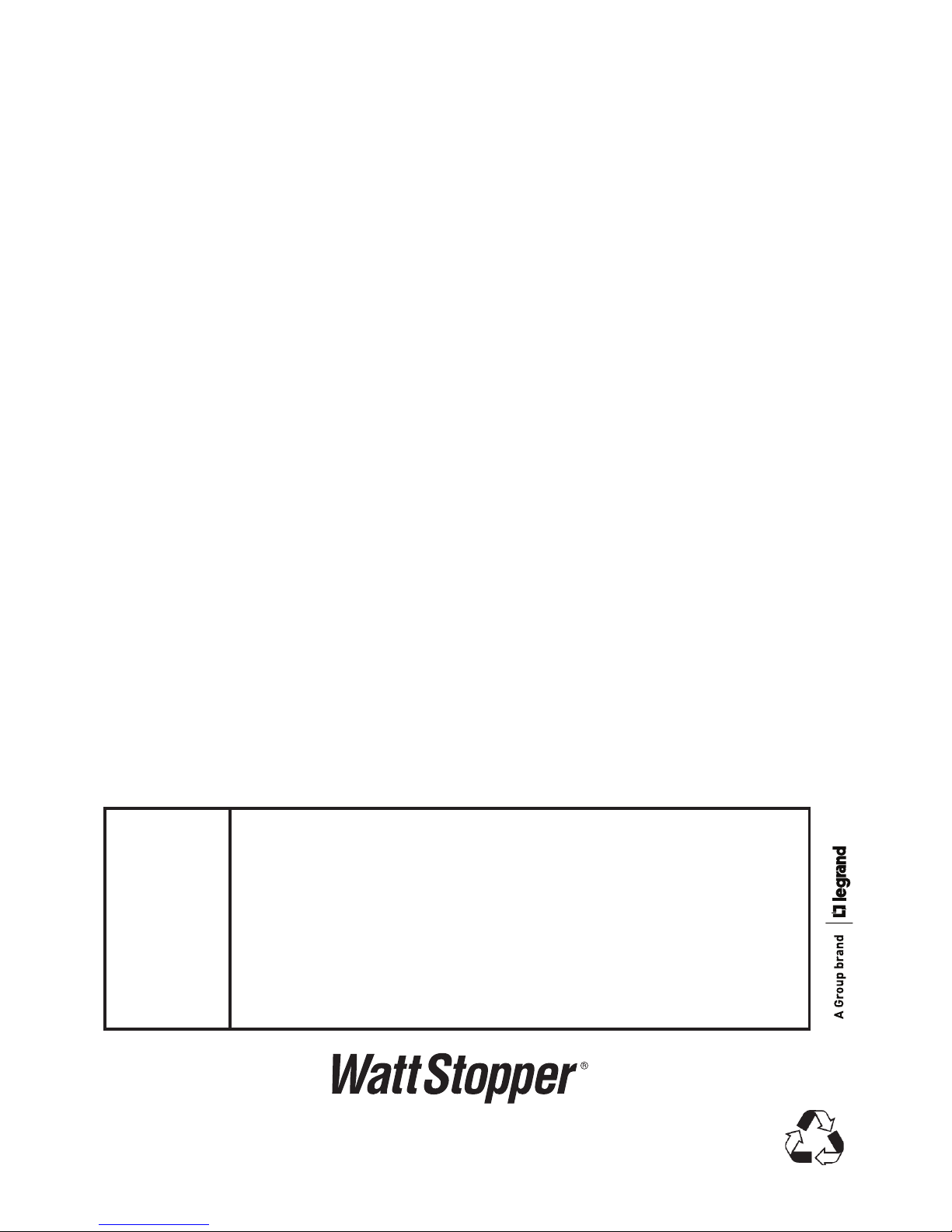
a. Locate the configuration button inside the
LMRH-101 battery compartment.
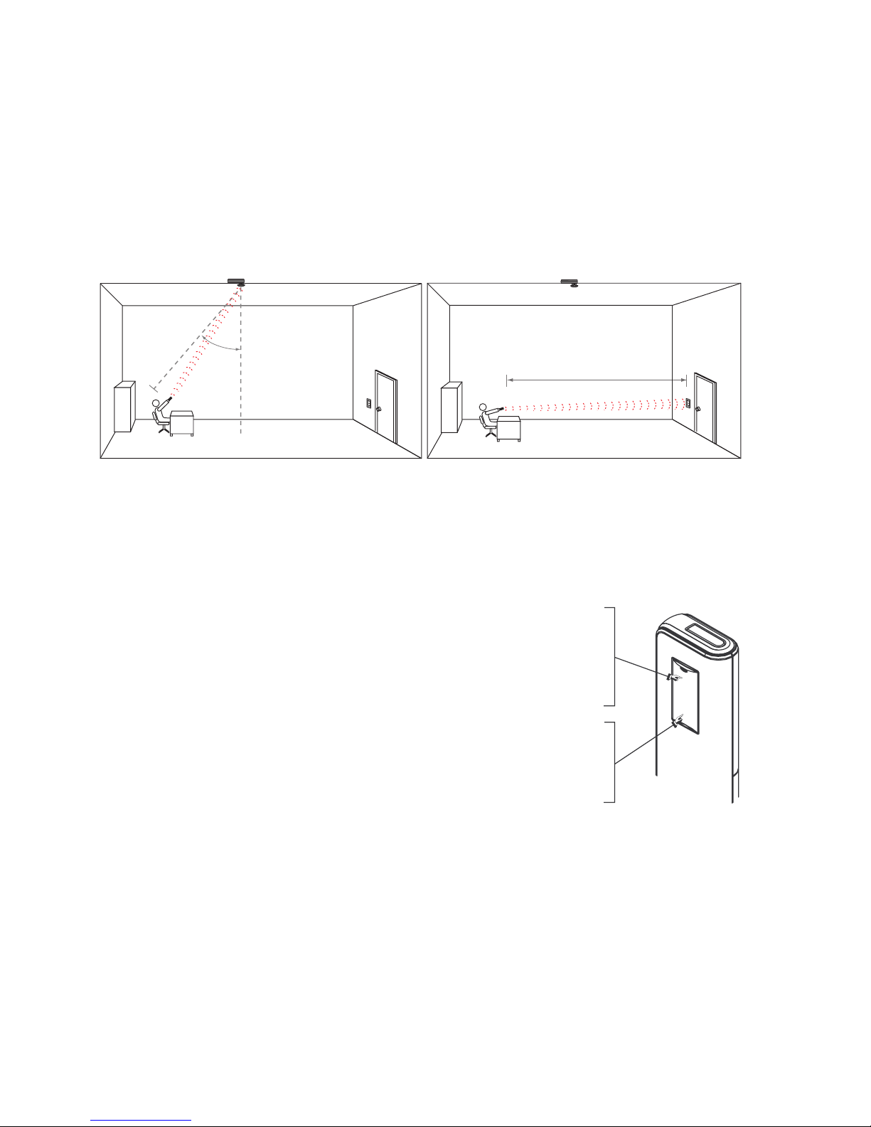
b. Point the LMRH-101 at a DLM IR device.
c. Press and hold the configuration button
until the red LED in the battery compartment begins blinking
(approximately 3 seconds), then release the button. Make sure the
LMRH-101’s red LED continues to blink, then observe the following:
- The Red LEDs on all other DLM devices on the network start blinking
rapidly (2x/second). The LEDs continue to blink until you exit PnL.
- All loads on the DLM local network turn OFF immediately after entering
PnL. After 1 second, load 1 turns ON.
Step 2: Load Selection
A quick press on the LMRH-101’s configuration button turns OFF load 1
then turns on the next load in sequence. Keep pressing the configuration
button to step through all the loads connected to the DLM local network.
When a load turns ON the blue LED is lit brightly on all switch buttons and
sensors bound to the load.
- To bind the load to the LMRH-101: While the load is ON press the
paddle making sure that the blue LED turns ON brightly.
- To unbind a load: While the load is ON and the blue LED is brightly
lit, press the paddle. The LED goes dim to indicate the paddle on the
handheld remote no longer controls this load.
- A quick press on the configuration button turns ON the next load.
- Repeat until the paddle is bound to all the loads you want it to control.
Note: more than one load can be assigned to the paddle and a load can
be assigned to multiple devices in the DLM network.
Step 3: Exit Push n’ Learn (PnL)
a. Point the LMRH-101 at a DLM IR device.
b. Press and hold the LMRH-101 configuration button until the red LED
in the battery compartment stops blinking (approximately 3 seconds),
then release the button.
Point at
DLM Device
Conguration
Button
Red LED

RESET PROCESS
Load binding reset - To clear the unit so that it is not bound to any load:
1. Do not point the LMRH-101 toward any DLM IR enabled device.
2. Press and hold the configuration button in the battery compartment until
the red LED goes solid ON (approximately 10 seconds).
Device reset - To get the unit back to its default Plug n’ Go state (bind to all
loads):
1. Do not point the LMRH-101 toward any DLM IR enabled device.
2. Press and hold the configuration button in the battery compartment for
20 seconds.
System Reset - This reset returns ALL DLM devices to their factory default
PnG settings. All system settings will be reset; all customized binding
relationships will be lost. All PnG functionality will be restored. To return
all devices on the DLM local network to PnG using the LMRH-101:
1. Point the LMRH-101 at an IR enabled DLM local network device.
2. Press and hold the configuration button in the battery compartment until
the red LED starts blinking to put the DLM local network into PnL (see
Step 1 in UNIT ADJUSTMENT for details). Release the button.
3. Press and hold the configuration button again for approximately 20 seconds,
until the red LED on the DLM devices resume blinking rapidly (approximately
2x/second).
TROUBLESHOOTING
LED on the
remote
doesn’t
light
Press the button. If the LED doesn’t light:
• ChecktoseeiftheLEDisactuallylit,butverydim.
This is normal. Press the top of the button to fully
turn ON the LED.
• Checkbatteries.Replaceifneeded.
• Remove the batteries for 5 minutes. After 5 minutes,
reinstall the batteries and try again.
Please
Recycle
2800 De La Cruz Boulevard, Santa Clara, CA 95050
Technical Support: 800.879.8585 • www.wattstopper.com
Please
Recycle
2800 De La Cruz Boulevard, Santa Clara, CA 95050
Technical Support: 800.879.8585 • www.wattstopper.com
12512r2 7/2010
Table of contents
Other wattstopper Remote Control manuals
Popular Remote Control manuals by other brands

HTW
HTW iControl user guide

Universal Remote Control
Universal Remote Control PHAZR-5 operating instructions

Miles Industries
Miles Industries GV60 Operation

Mitsubishi Electric
Mitsubishi Electric PAR-32MAA-J installation manual

Videofied
Videofied KF210 Installation sheet

Toshiba
Toshiba 2358 9721 Quick setup guide