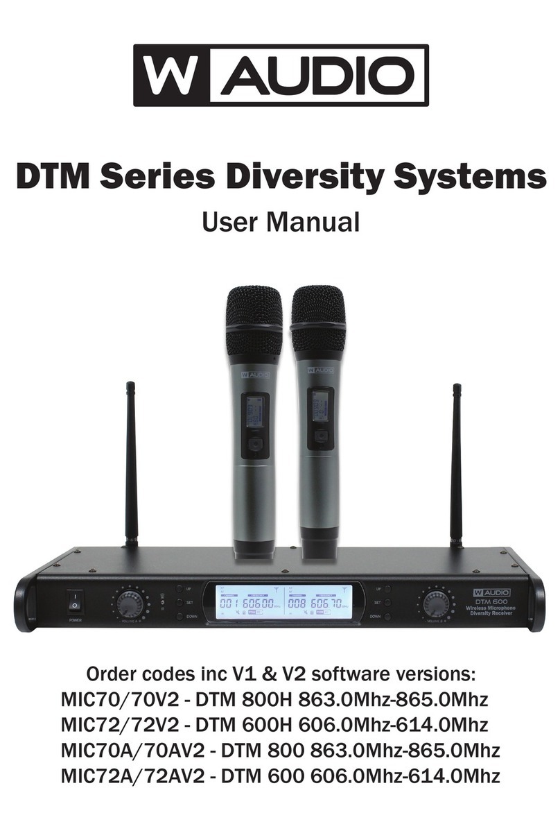
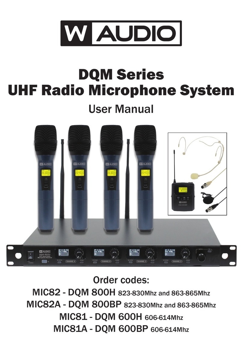
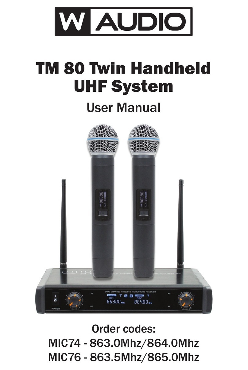
Waudio MIC70-DTM 800H User manual

Order codes:
MIC70 - DTM 800H 863.0Mhz-865.0Mhz
MIC72 - DTM 600H 606.0Mhz-614.0Mhz
MIC70A - DTM 800 863.0Mhz-865.0Mhz
MIC72A - DTM 600 606.0Mhz-614.0Mhz
DTM Series Diversity Systems
User Manual

www.prolight.co.uk DTM Series User Manual
2
Safety adviceSafety advice
WARNING
FOR YOUR OWN SAFETY, PLEASE READ THIS USER MANUAL
CAREFULLY BEFORE YOUR INITIAL START-UP!
• Beforeyourinitialstart-up,pleasemakesurethatthereisnodamagecausedduringtransportation.
• Shouldtherebeanydamage,consultyourdealeranddonotusetheequipment.
• Tomaintaintheequipmentingoodworkingconditionandtoensuresafeoperation,itisnecessary
fortheusertofollowthesafetyinstructionsandwarningnoteswritteninthismanual.
• Pleasenotethatdamagescausedbyusermodicationstothisequipmentarenotsubjecttowarranty.
IMPORTANT:
The manufacturer will not accept liability for any resulting damages caused by the non-observance
of this manual or any unauthorised modication to the equipment.
OPERATING DETERMINATIONS
Ifthisequipmentisoperatedinanyotherway,thanthosedescribedinthismanual,theproductmaysufferdamageand
thewarrantybecomesvoid.Incorrectoperationmayleadtodangere.g:short-circuit,burnsandelectricshocksetc.
Incaseofmalfunctionthisunitshouldbereturnedforserviceorinspection.
Donotendangeryourownsafetyandthesafetyofothers!
Incorrectinstallationorusecancauseseriousdamagetopeopleand/orproperty.
• Neverletthepowercablecomeintocontactwithother
cables.Handlethepowercableandallmainsvoltage
connectionswithparticularcaution!
• Neverremovewarningorinformativelabelsfromtheunit.
• Donotopentheequipmentanddonotmodifytheunit.
• Donotconnectthisequipmenttoadimmerpack.
• Donotswitchtheequipmentonandoffinshortintervals,
asthiswillreducethesystem’slife.
• Onlyusetheequipmentindoors.
• Donotexposetoammablesources,liquidsorgases.
• Alwaysdisconnectthepowerfromthemainswhen
equipmentisnotinuseorbeforecleaning!Onlyhandle
thepower-cablebytheplug.Neverpullouttheplugby
pullingthepower-cable.
• Makesurethattheavailablevoltage9VDC,1500mA.
(240VAC~50Hzpowersupplyincluded)
• Makesurethatthepowercableisnevercrimpedor
damaged.Checktheequipmentandthepowercable
periodically.
• Iftheequipmentisdroppedordamaged,disconnectthe
mainspowersupplyimmediatelyandhaveaqualied
engineerinspecttheequipmentbeforeoperatingagain.
• Iftheequipmenthasbeenexposedtodrastic
temperatureuctuation(e.g.aftertransportation),
donotconnectpowerorswitchitonimmediately.
Thearisingcondensationmightdamagetheequipment.
Leavetheequipmentswitchedoffuntilithasreached
roomtemperature.
• Ifyourproductfailstofunctioncorrectly,stopuse
immediately.Packtheunitsecurely(preferablyinthe
originalpackingmaterial),andreturnittoyourProLight
dealerforservice.
• Onlyusefusesofsametypeandrating.
• Repairs,servicingandpowerconnectionmustonlybe
carriedoutbyaqualiedtechnician.THISUNITCONTAINS
NOUSERSERVICEABLEPARTS.
• Thisxtureisforprofessionaluseonly-itisnotdesigned
fororsuitableforhouseholduse.Theproductmustbe
installedbyaqualiedtechnicianinaccordancewithlocal
territoryregulations.Thesafetyoftheinstallationisthe
responsibilityoftheinstaller.Thexturepresentsrisksof
severeinjuryordeathduetorehazards,electricshock
andfalls.
• WARRANTY:Oneyearfromdateofpurchase.
CAUTION!
KEEP THIS EQUIPMENT
AWAY FROM MOISTURE,
RAIN AND LIQUIDS, AND
OUT OF DAMP/HUMID
ENVIRONMENTS
CAUTION!
TAKE CARE USING
THIS EQUIPMENT!
HIGH VOLTAGE-RISK
OF ELECTRIC SHOCK!!

www.prolight.co.uk DTM Series User Manual
3
Product overview & technical specications
DTMserieswirelessmicrophonesfeaturetwinUHFbeltpackorhandheldsystemswith20(863-865Mhz)or80
(606-614Mhz)selectablefrequencies.AvailableineitherChannel38(606-614Mhz)fortheDTM600orChannel70
(863-865Mhz)fortheDTM800;bothsystemsutiliseatruediversity,fullbandwidthreceiverfortheultimateinRFstability.
Outstandingvocalreproductionandstablewirelessconnectivityallowfreedomofmovementonstage.Thesesystemsoffer
crystalclearsoundreproductionandrocksolidreliability.Metalbodiedtransmittersfeatureergonomicdesignwitharugged
housingtostanduptotherigoursoftheroad.Suppliedwithafoamlinedcarrycaseforprotectionduringtransit.Theexibility
ofthehandheldsystemsmaybeincreasedbypurchasingtheadditionalDTM600BP.
DTM Series Diversity Systems
Inthehandheldsystembox:
1 x receiver, 2 x wireless microphones,
1 x PSU, 1 x audio lead & 1 x user manual
Inthebeltpackbox:
1 x receiver, 2 x beltpacks, 1 x headset
microphone, 1 x lavalier microphone, 1 x PSU,
1 x audio lead & 1 x user manual
Specications DTM 800H Twin Handheld
Diversity System
DTM 600H Twin Handheld
Diversity System
DTM 800 Twin Beltpack
Diversity System
DTM 600 Twin Beltpack
Diversity System
Operatingfrequency 863.0Mhz-865.0Mhz 606.0Mhz-614.0Mhz 863.0Mhz-865.0Mhz 606.0Mhz-614.0Mhz
Powersupply DC9V,1500mA(adaptorsupplied) DC9V,1500mA(adaptorsupplied)
Ordercode MIC70 MIC72 MIC70A MIC72A
•PhaseLockLoop(PLL)
•IRsyncfacilityforsimplesetup
•Truediversityreceiver
•863-865Mhz-20frequencies
or606-614Mhz-80frequencies
•LargeLCDreceiverdisplay
includingRFlevel,AFlevel,
channelandfrequency
•LCDtransmitterdisplay
•Autofrequencyscanning
•BalancedXLRoutputfor
eachchannelplusunbalanced
mixedoutput
•Frequencyresponse(handheld):
40Hz-15kHz
•Transmitterbatteryconguration:
2x1.5VAA(notsupplied)
•Audiooutputlevel:400mV
•Dynamicrange:96dB
•Receiverpowersupply:9VDC
(mainsadaptorsupplied)
•1Ufullwidthrackmountreceiver

www.prolight.co.uk DTM Series User Manual
4
Receiver front
panel identication:
1.PowerSwitch
On/Offcontrolforthesystemreceiver
2.VolumeControl–ChannelA
Thereceiversoutputvolumeis
adjustable.Turnthelevelcontrolanti
clockwisetothelowestsetting,or
turnclockwisetoadjusttothehighest
setting.Eachchannelfeaturesan
independentvolumecontrol.
3.IRTransceiver
TheIRtransceiverisusedto
communicatewiththesystems
transmittersduringsetup.
4.UpButton–ChannelA
5.SetButton–ChannelA
6.DownButton–ChannelA
7.Display
Thereceiverfeaturesabacklitdisplay
allowingtheusertoseeinformation
aboutthereceiverincludingfrequency,
channels,mutestatus,audio,
RFstatusandbatterylevel.
8.DownButton–ChannelB
9.SetButton–ChannelB
10.UpButton–ChannelB
11.VolumeControl–ChannelB
Thereceiver’soutputvolumeis
adjustable.Turnthelevelcontrolanti
clockwisetothelowestsetting,or
turnclockwisetoadjusttothehighest
setting.Eachchannelfeaturesan
independentvolumecontrol.
Receiver rear panel
identication:
12.Antenna–ChannelA
TheantennareceivestheRFradio
signalfromthetransmitterunit.For
optimumreception,orientatevertically.
Receptionmaybeimpairedbyobstacles
betweenthetransmitterandreceiver.
Highpowerelectricalequipmentcan
causeunwantedinterference.
13.BalancedAudioOutputB
Individual,balancedaudiooutputs
via3pinXLRforaudiochannelB.
14.BalancedAudioOutputA
Individual,balancedaudiooutputs
via3pinXLRforaudiochannelA.
15.Audio(MIX)Output
6.35mm(1/4”)jacksocketoutputting
anunbalanced,linelevelaudiooutput
featuringbothaudiochannels.
16.DCPowerInput
Thereceiverispoweredbyastandard
DCpowerinput9VDC,1500mA
regulatedvoltagesupply.
17.Antenna–ChannelB
TheantennareceivestheRFradio
signalfromthetransmitterunit.For
optimumreception,orientatevertically.
Receptionmaybeimpairedbyobstacles
betweenthetransmitterandreceiver.
Highpowerelectricalequipmentcan
causeunwantedinterference.
1 2
12 13 14 15 16 17
3 84 95 106 117
Operating instructions

www.prolight.co.uk DTM Series User Manual
5
Display Identication:
1.RFLevel
TheRFlevelindicatorisavisualrepresentationoftheradiofrequencysignalstrengthutilisinga10segmentbargraph.
Astheradiosignalreceivedisreduced,thebargraphwillreduce.
2.AFLevel
TheAFlevelindicatorisavisualrepresentationoftheaudiosignalstrengthutilisinga10segmentbargraph.
Astheaudiosignaluctuatesbargraphwillindicatethis.
3.Channelindicator
DisplaysthecurrentRFchannelinusebythetransmitter/receiver.
4.Frequency
DisplaysthecurrentRFfrequencyinusebythetransmitter/receiver.
5.BatteryLevel
Thereceiverdisplaysthecurrentbatterylevelinthetransmittersallowingremotemonitoringofthetransmittersbatterylevel.
6.IRSync
Duringsynchronisation,theIRSyncwillasharadiatingsymbol.
7.Lock
Thereceiverfeaturesalockfunctiontopreventaccidentalchangestothesettings.PressandholdLOCKtounlockthemenu
system.Afterashortperiodofinactivity,thedisplaywillautomaticallylock.
8.Hi/Lotransmitpower
TheusermayselecttheRFtransmissionpowerfromthemenusystem.Whenusedincloseproximity,thetransmittersshould
besettoLoorovergreaterdistances,settoHi.
Operating instructions
Operation:
• Carefully,lifttheantennaeintotheverticalposition.
• Connecttheincludedpowersupplytoasuitable240VAC~50HzmainsvoltageoutletandplugtheDCconnector
intotheDC.PowerInputontherearpanelofthereceiver(9VDC,1500mAminimum).
• Usingthesuppliedaudiocable,connecttheMIXOUTontherearpanelofthereceiverforbothaudiochannels
tothemixer’saudiolineinput.ThereceiveralsofeaturesbalancedXLRoutputs,oneforeachchannel.
• Switchonthepowertothereceiver,checkingthedisplaybacklightilluminates.
• Openthebatterycompartmentonthetransmitter(Beltpack–slidedownwardsawayfromthebeltclip.Handheld-unscrew
thelowerportion).Installtheappropriatebatteriesintothetransmitter,takingcaretoobservetheorientationandpolarity.
Onlyusehighquality,alkalinetypebatteries.Retthebatterycompartmentcovercarefully.
• Switchonthetransmitter,whenswitchedonthedisplayonthetransmitterwillilluminate.
Ifthedisplaydoesilluminateorglowsdimly,thebatterywillrequirereplacement.
• Adjustthevolumeonthefrontpanelofthereceiverforeachofthechannels.
• FollowtheIRSyncOperationfullytoensurethetransmittersarelinkedcorrectlytothereceiverunit.
Failuretofollowthisfullywillpreventthemicrophonesystemfromoperatingcorrectly.
• Channel(Frequency)Setup:
PressandholdtheSETbuttontounlockthemenufunction.
TheCHANNELmodewillash,usetheUP/DOWNbuttonstoselect
thedesiredchannel,thefrequencywillautomaticallychange.TheDTM
800has20availablechannelswithinthe863-865Mhzrange,where
astheDTM600has80availablewithinthe606-614Mhzrange.
Afterchangingthechannel,theIRsyncmustbecarriedouttoensure
thetransmitterismatchedforcorrectoperation.
ashes changes

www.prolight.co.uk DTM Series User Manual
6
Operation continued:
• FrequencyScanMode:
Toallowtheusertoselectafrequencyfreefrominterference,thereceiver
featuresafrequencyscanmode.Firstly,switchonanytransmittersfromother
systemsinthevicinity.PressandholdtheSETbuttontounlockthemenu
functionandthenpressSETuntilthedisplayshowsarectangleunderneath
thefrequencyheader.UsetheUporDownkeystocommencescanning.The
receiverwillstopscanningwhenitreachestherstavailablefrequency.Further
scanningcanbetriggeredbypressingtheup/downbuttonagain.Afterchang-
ingthefrequency,theIRsyncmustbecarriedouttoensurethetransmitteris
matchedforcorrectoperation.
• TransmitterPowerMode:
TheusermayselecttheRFtransmissionpowerfromthemenusystem.When
usedincloseproximity,thetransmittersshouldbesettoLoorovergreater
distances,settoHi.PressandholdtheSETbuttontounlockthemenufunction,
thenpresstheSETbuttontwicemoreuntilthePOWselectionashes.Pressthe
SETbuttontoconrmselection.Afterchangingthepowersetting,theIRsync
mustbecarriedouttoensurethetransmitterismatchedforcorrectoperation.
• IRSyncOperation:
Aftermakingchangestothesettingsonthereceiver,theIRSyncoperation
shouldbecarriedouttoensurethesettingsarereplicatedintothetransmitter
toensurecorrectoperation.
Poweronboththetransmitterandreceiver,cyclethruthemenusystemonthe
receiveruntilallsettingsarecorrect.PressandholdtheSETbuttontotrigger
theIRSyncoperation.TheIRSyncindicatorwillshowtheradiatingsymbol,
whiletheradiatingsymbolisashing,directthedisplayontherelevanttrans-
mittertowardstheIRTransceiver,thetransmitterwillthenchangetomatch
thesettingsonthereceiver.Themicrophoneisnowreadyforuse.Note:The
beltpacktransmitterIRTransceiverislocatedinsidethebatterycompartment.
Operating instructions
Handheld transmitter
identication:
1.Grille
2.LCDDisplay
3.IRTransceiver
4.PowerSwitch
5.Batterycompartment
1
2
3
4
5
WhenthePOWisashing,
theHIcanbeadjustedtoLO
ashes changes
IRSYNC

www.prolight.co.uk DTM Series User Manual
7
Operating instructions & troubleshooting
Beltpack transmitter
identication:
1.MicrophoneInput
2.VolumeControl
3.On/OffSwitch
4.PowerIndictor(illuminateswhen
batteryislowandrequireschanging)
5.Antenna
6.LCDDisplay
7.IRTransceiver
8.Batterycompartment(careshould
betakentoobservebatterypolarity)
9.Batterycover
1 2 3 4 5
6
8
9
7
Troubleshooting:
Problem Possible cause Solution
Receiver–nosound PowerbuttonisintheOFFposition.DCpoweradapter
isnotpluggedin Turnonthepowerbuttonpluginthepoweradapter
Receiver–noLED
Microphone-nosound
butLEDindicatorsarelit
Mictransmitterisoutofrange.Micisswitchedoff.Mic
volumeitturneddown.Batteriesinmicarenotinstalled
properly.Receiverisnotconnectedtoanampormixer.
Ensurethatthemiciswithinrange.Turnonthemicswitch.
Turnupthemicvolumeonthereceiver.Reinstallorusenew
batteries.Connectanoutputcabletoanampormixer
Distortedsoundorfeedback
The4micsmaybetooclosetogether.Batteriesarerunning
outofcharge.Micvolumemaybetoohigh.Possible
interferencefromanothersource.
Increasethedistancebetweenmics.Replacethebatteries.
Reducethevolume.Movethesystemawayfromother
electricsources.
Beltpacktransmitterplusheadsetandlavaliermicrophones
tobeusedinplaceofthehandheldtransmitter.
Optional DTM Series
Add On Beltpack Kits Specications DTM 800BP DTM 600BP
Operatingfrequency 863.0Mhz-865.0Mhz 606.0Mhz-614.0Mhz
Batterytype 2x1.5VAA(notsupplied)
Ordercode MIC71 MIC73
NOTE:
TheDTM600/800systemisshippedwithtwohandheldtransmitters.Thereceiverinthissystemfeaturesadual
channelreceiverallowingbothhandheldmicrophonestobeusedsimultaneously,anadditionalbeltpackkitmaybe
purchasedifrequiredtobeusedinplaceofthehandheldtransmitters.Eachreceiverchannelinthissystemmayonlybe
usedwithonetransmitteratanyonetime.Iftheuserattemptstopoweron,andusetwotransmitterswithonereceiver
thesystemwillmalfunctionandnotoperatecorrectlyasonetransmitterwillcutouttheRFRadiosignaltothesecond
transmitter.
Availableintwofrequencyranges,theDTM800seriesisforuseinthe863-865MhzCH70bandlicensefreewhilethe
DTM600seriesisforuseinthe606-614MhzCH38band.Tooperatemicrophonesinthe606-614MhzCH38bandthe
usermustobtainalicensefromtherelevantauthoritiesbeforeusingtheproduct.

www.prolight.co.uk DTM Series User Manual
8
WEEE notice
Correct Disposal of this Product
(Waste Electrical & Electronic Equipment)
(Applicable in the European Union and other European countries
with separate collection systems)
Thismarkingshownontheproductoritsliterature,indicatesthatitshouldnotbedisposedof
withotherhouseholdwastesattheendofitsworkinglife.Topreventpossibleharmtothe
environmentorhumanhealthfromuncontrolledwastedisposal,pleaseseparatethisfromother
typesofwastesandrecycleitresponsiblytopromotethesustainablereuseofmaterialresources.
Householdusersshouldcontacteithertheretailerwheretheypurchasedthisproduct,ortheir
localgovernmentofce,fordetailsofwhereandhowtheycantakethisitemforenvironmentally
saferecycling.
Businessusersshouldcontacttheirsupplierandcheckthetermsandconditionsofthe
purchasecontract.Thisproductshouldnotbemixedwithothercommercialwastesfordisposal.
This manual suits for next models
3
Table of contents
Other Waudio Microphone System manuals