Wavelength Electronics WTC3293 User manual

ORDERING INFORMATION
PART NO DESCRIPTION
WTC3243 ±2.2 A Temperature Controller
WTC3243HB ±2.2 A Li-Ion Battery-Compatible
Temperature Controller
WTC3293 Evaluation Board for WTC3243
Temperature Controller
WEV300 Thermal Management Kit, no fan
WEV301 Thermal Management Kit, 5 V fan
WEV302 Thermal Management Kit, 12 V fan
PRECISION, STABILITY & VERSATILITY
The WTC3243 is a compact, analog PI (Proportional,
Integral) control loop circuit optimized for use in ultrastable
thermoelectric temperature control applications. It easily
handles variable operating conditions with a stability of better
than 0.0009ºC. The temperature setpoint is set by a remote
voltage signal. It is capable of controlling both thermoelectric
The WTC3293 Evaluation Board is available to quickly
integrate the WTC3243 into your system and can be
optimized for sensor type. Use the adjustable trimpots to
integrator time constant.
BUILT-IN SAFETY
To protect the device, heat and cool limits can be set
independently. This safety feature guarantees that your
thermoelectric cooler will never be driven beyond your
LEADING EDGE APPLICATIONS
The robust and reliable WTC3243 has been designed
into electro-optical systems, airborne instrumentation,
spectroscopic monitors, and medical diagnostic
equipment. It is particularly well-suited to applications
where temperature is scanned across ambient.
FEATURES AND BENEFITS
• Linear PI Control Stability of 0.0009°C
• Heat and Cool Current Limits
• Adjustable Sensor Bias Current
• Drive ±2.2 A of TEC or Resistive Heater Current
• Small Size of 1.3” X 1.28” X 0.313”
• Supports Thermistors, RTDs, and IC Sensors
• Single Supply Operation: +5 V to +30 V
• 14-pin DIP PCB Mount
• Monitor Actual Temperature
• Quickly and easily integrated with WTC3293
Evaluation Board
CONTENTS
QUICK CONNECT GUIDE 2
WTC3293 EVALUATION BOARD SCHEMATIC 4
PIN DESCRIPTIONS — WTC3243 5
PIN DESCRIPTIONS — WTC3293 EVAL BOARD 6
ELECTRICAL SPECIFICATIONS — WTC3243 8
SAFETY & THERMAL DESIGN CONSIDERATIONS 11
OPERATING INSTRUCTIONS — WTC3243 + EVAL 12
DESIGN GUIDE — WTC3243 20
ADDITIONAL TECHNICAL NOTES 28
TROUBLESHOOTING 32
MECHANICAL SPECIFICATIONS 34
CERTIFICATION AND WARRANTY 36
e
PAGE
Pb
RoHS
Compliant
Applies to WTC3243 Revisions A - C
WTC3243HB Revisions A - C
WTC3293 Revision B
© February 2022
The prior revision of the evaluation board was black. Click
www.teamwavelength.com/download/Datasheets/wtc3293a.pdf
for the datasheet for the WTC3293 revision A.
406-587-4910
www.teamWavelength.com
WTC3243 & WTC3293
Ultrastable TEC Controller & Evaluation Board
DATASHEET AND OPERATING GUIDE
NOT RECOMMENDED FOR NEW DESIGNS - SEE THE WTC32ND
WTC3243
WTC3293

© 2022 www.teamWavelength.com 2
WTC3243 TEMPERATURE CONTROLLER
14
13
12
11
10
9
8
1
2
3
4
5
6
7
VS
VSET
LIMA
LIMB
P
+1V
I
VDD
GND
OUTB
OUTA
BIAS
S+
SG
Power Drive Supply Input
Voltage Setpoint
Limit A
Limit B
Proportional Gain Resistor Connection
+1 Volt Reference
Integrator Time Constant Resistor Connection
Control Electronics Supply Input
Ground
Thermoelectric Output B
Thermoelectric Output A
Sensor Bias Current Resistor Connection
Sensor Connection & Act T Monitor
Sensor Gain Resistor Connection
QUICK CONNECT GUIDE
WTC3243 Temperature Controller Pin Layout page 2
WTC3293 Evaluation Board Top view page 2
WTC3243 Controller Quick Connect Diagram page 3
WTC3243 Test Loads page 3
WTC3293 Eval Board Electrical Schematic page 4
!
Visit the Wavelength Electronics website for the most
accurate, up-to-date, and easy to use SOA calculator:
www.teamwavelength.com/support/design-tools/soa-tc-calculator/
Figure 1. WTC3243 Pin Layout -- Top View
Figure 2. WTC3293 Evaluation Board Top View
Figure 1 shows the pin layout and descriptions for the
WTC3243.
IF YOU ARE UPGRADING FROM THE WHY5640: The
position of Pin 1 on the WHY5640 is reversed (or mirrored)
relative to the position of Pin 1 on the WTC3243.
Figure 2 is the top view of the WTC3293, illustrating the
onboard switches, trimpots, and connectors.
Figure 3 is the Quick Connect schematic for the WTC3243
using a thermistor temperature sensor.
WTC3243
Sockets
Output Terminal Block
Optional Supply Input
Switchcraft RAPC712X
2.50 mm ID, 5.50 mm OD
USE
WITH
WTC3243
Temperature
Controller
ONLY
WAVELENGTH
ELECTRONICS
Input Power
Terminal Block
Output Current
Enable/Disable
Switch
Auxiliary
Terminal
Block
Monitors
Terminal
Block

© 2022 www.teamWavelength.com 3
WTC3243 TEMPERATURE CONTROLLER
R1
R1 = 10 kΩ, ¼ W resistor
SENSOR-
SENSOR+
Simulated Thermistor
R
LOAD
OUTB
OUTA
R
LOAD
= 1 Ω, Rated >25 W
Thermal Test Load
QUICK CONNECT GUIDE, cont’d
V
S
V
DD
TIE GROUND CONNECTIONS DIRECTLY TO PIN 13
1
WTC3243
Temperature
Controller
1
2
3
4
5
6
7
14
13
12
11
10
9
8
Actual
Temperature
Monitor voltage
VDD
RT
RBIAS
RI
RP
RLIMA
RLIMB
Adjusting PI
Control Loop
Adjusting Limit
Currents
VSET
VSET = Sensor Resistance X Sensor Bias Current
1
1
-+
TOP VIEW
NC
OR
D/A
VDD
Bandgap
Voltage
Reference
W
CCW
OR
Figure 3. WTC3243 Quick Connect for TEC with Thermistor
Figure 4. Recommended Test Loads
QUICK CONNECT LEGEND
FUNCTION WTC3243 & EVAL BOARD WTC3243 ALONE
Limits Adjust LIMA & LIMB Table 6 on page 17
Equation 5 RLIMA & RLIMB Table 9 on page 25
Control Parameters
PGAIN Table 5 on page 14
Equation 1 RPTable 11 on page 27
I TERM Table 5 on page 14
Equation 3 RITable 12 on page 27
Bias Current
Sensor Bias Switch Table 4 on page 13
Figure 8 RBIAS
Table 10 on page 26
Equation 6 & Equation 7
Gain Jumper Table 10 on page 26
Figure 9 RG
Table 10 on page 26
Equation 8
Thermistor (RT)See Thermistor datasheet
The same values can more simply be determined using the Circuit Design Calculator, available online at:
www.teamwavelength.com/support/design-tools/wtc-calculator/. Wavelength recommends using this utility.
RECOMMENDED TEST LOAD
load in place of the TEC or resistive heater, connected
directly to Pin 11 and Pin 12 on the controller, as shown in
Figure 4.
Recommended test load:
• MP9100-1.00-1%. This resistor may need to be attached
to a heatsink.
thermistor. Figure 4 shows a simple adjustment test circuit.

© 2022 www.teamWavelength.com 4
WTC3243 TEMPERATURE CONTROLLER
WTC3293 EVALUATION BOARD SCHEMATIC
VDD
1
VSET
2
LIMA
3
LIMB
4
P
5
+1V
6
I
7SG 8
S+ 9
BIAS 10
OUTA 11
OUTB 12
GND 13
VS 14
U1
WTC3243
Q1
3904
Q2
3904
U2
2.5V
VDD
VDD
VDD
VDD
VDD
LED
GREEN
VDD
OUTA
OUTB
S+
+1V
P
I
VSET
LIMA
LIMB
BIAS
S-
VDD
VS
PGND
OUT A
OUT B
SENSOR+
SENSOR-
LIM A LIM B
P GAIN
I TERM
SET T
SGND
0.00
2.5V
SET T
COM
GND 1
PWR 2
P1
Power Jack
VDD
1mA
100uA
10uA
EXT VSET
VDD
1
2
3
TB1
Input Connections
REN
ACT T
1
2
3
4
TB4
Output Connection
2
3
1
84
U4A
LM393AD
6
5
7
84
U4B
LM393AD
1
23
Q3
PMBT3906
VS
D2
LM4040 2.5V
CU4
0.1uF
CU3
0.1UF
VDD
C4
0.1UF
VDD
D1
1N4148
+C3
4.7 uF
+C1
4.7 uF
+C2
4.7 uF
VS
VDD
VS
VDD
VDD
CU5
0.1UF
VDD
R52
N/L
R53
N/L
R54
N/L R55
N/L
Limit B:
To set a Fixed Limit
Remove R19 and load R53
Limit A:
To set a Fixed Limit
Remove R18 and load R52
P Gain:
To set a Fixed P Gain
Remove R8 and load R54
I TERM:
To set a Fixed I Term
Remove R13 and load R55
TP7
TP4
TP3
TP5
CW
W
CCW R5
200K
TP6
C5
0.1UF
C6
0.1UF
R50
N/L
R51
N/L
Set T:
To set a Fixed Set point Voltage
Remove R47 & R48 and load R50 & R51
Refer to Datasheet for Equations
TP2
TP1
1
2
3
JP2
T X
2
1
3
S1
ENABLE
CW
W
CCW
R4
200K
C7
0.1UF
9
10
8
411
U5C
OP747ARU
5
6
7
411
U5B
OP747ARU
13
12
14
411
U3D
OP747ARU
2
3
1
411
U3A
OP747ARU
5
6
7
411
U3B
OP747ARU
9
10
8
411
U3C
OP747ARU VSET JUMPER
VDD
VDD
R47
0.00
R48
0.00
ST3
ST4
ON S2
SW DIP-3 SMT
1
2
3JP3
Gain
1
2
3
JP1
VS+VDD Jumper
Bias Selection
FAN+
FAN-
R23
100K R26
100K
R28
1.0K
R16
10.0K
R27
1.0K
R31
1.0K
R33
10.0K
R32 10.2K
R34
1.0K
R35
10.2K
R7
10.0K
R36
10.0K
R15
90.9K
R25
9.76K
R24
10.0K
3.3V
R29
287
R14
287
LIMB
LIMA
R13
0.00
R8
0.00
R10
10.0K
R17
10.0K
R9
10.0K
R19
1.50K
R18
1.50K
VDD
R21
20K
R22
2K
R20
200K
R30
20K
R11
10.0K
R6
10.0K
1
2
3
4
5
6
TB2
TB6
1
2
3
4
5
6
TB3
TB6
COM
HVSET
CW
CCW
R1
5k
CW
CCW
R2
5k CW
CCW R3
5k
ST1
ST2
I2
I1
P2
P1
LB2
LB1
LA1
LA2
RSET
x10
x1
2
1
DAQ
FAILSAFE
PROTECTION
CIRCUIT

© 2022 www.teamWavelength.com 5
WTC3243 TEMPERATURE CONTROLLER
PIN DESCRIPTIONS — WTC3243
Table 1. WTC3243 Temperature Controller Pin Descriptions
PIN NAME PIN DESCRIPTION
1 VDD Control Electronics Power Supply Input. Connect a +4.5 V to +30 V power supply to VDD (Pin 1)
and GND (Pin 13). NOTE: can be connected to VS (Pin 14).
2 VSET Voltage Setpoint [Setpoint voltage equations are sensor dependent & noted on operating diagrams].
Connect a voltage source between VSET (Pin 2) and GND (Pin 13) to control the temperature setting.
3 LIMA Limit A. A resistor connected between LIMA (Pin 3) and GND (Pin 13) limits the output current drawn
4 LIMB Limit B. A resistor connected between LIMB (Pin 4) and GND (Pin 13) limits the output current drawn
5 P Proportional Gain Resistor Connection. Connect a resistor between P (Pin 5) and +1V (Pin 6) to
6 +1V +1 Volt Reference.
7 I Integrator Time Constant Resistor Connection. Connect a resistor between I (Pin 7) and +1V
8 SG Sensor Gain Resistor Connection. Connect a resistor between SG (Pin 8) and GND (Pin 13) to
adjust the Sensor Gain setting.
9 S+
Sensor Connection. Connect resistive and LM335 type temperature sensors across S+ (Pin 9) and
type temperature sensors. The negative terminal of the AD590 sensor connects to S+ (Pin 9) and the
positive terminal to VDD (Pin 1). AD590 operation requires that VDD be +8 V or greater.
10 BIAS Sensor Bias Current Resistor Connection. Connect a resistor between BIAS (Pin 10) and VDD
11 OUTA
Thermoelectric Output A. Connect OUTA (Pin 11) to the negative terminal on your thermoelectric
With NTC
Connect OUTA (Pin 11) to the positive thermoelectric terminal when using
12 OUTB
Thermoelectric Output B. Connect OUTB (Pin 12) to the positive terminal on your thermoelectric
With NTC
Connect OUTB (Pin 12) to the negative thermoelectric terminal when using
13 GND Ground. Connect the power supply ground connections to GND (Pin 13). All ground connections to
this pin should be wired separately.
14 VS
Power Drive Supply Input. Provides power to the WTC3243 H-Bridge power stage. Supply range
CAUTION:
limits before applying power to the device. NOTE: can be connected to VDD (Pin 1).
IF YOU ARE UPGRADING FROM THE WHY5640: The position of Pin 1 on the WHY5640 is reversed (or mirrored) relative
to the position of Pin 1 on the WTC3243.

© 2022 www.teamWavelength.com 6
WTC3243 TEMPERATURE CONTROLLER
PIN DESCRIPTIONS — WTC3293 EVALUATION BOARD
Table 2. WTC3293 Evaluation Board Pin Descriptions
SILKSCREEN
LABEL NAME FUNCTION
P1 Power Optional Supply Input. 2.5 mm jack power connection to VDD.
NOTE: Use either Input Supply (P1) or VDD on TB1 but not both.
ENABLE
ON/OFF Output Current ON/OFF NOTE: Keep
this OFF until the evaluation board is set up entirely. LED lights when ON.
P GAIN Trimpot Proportional Gain
I TERM Trimpot Integrator Time Constant
SET T 12-turn Trimpot Setpoint for temperature
LIM A 12-turn Trimpot Current Limit A Adjustment
LIM B 12-turn Trimpot Current Limit B Adjustment
TP1 Test Point 1
Used when eliminating trimpots in setpoint and limit circuits
TP2 Test Point 2
TP3 Test Point 3
TP4 Test Point 4
TP5 Test Point 5 P GAIN (measure resistance across TP5 and TP6)
TP6 Test Point 6 Reference point for P GAIN and I TERM
TP7 Test Point 7 I TERM (measure resistance across TP6 and TP7)
VDD Voltage Supply Power supply input for control electronics. Directly connected to WTC3243 VDD (Pin 1).
NOTE: Use either Input Supply (P1) or VDD on TB1 but not both.
VSVoltage Supply Power supply input for output stage. Directly connected to WTC3243 VS(Pin 14)
PGND Power Ground Directly connected to WTC3243 GND (Pin13)
FAN + Fan Positive Red wire connection
FAN - Fan Ground Black wire connection
2.5 V +2.5 V Reference
REN Remote Enable
0 V = ENABLED
Floating or >3 V = DISABLED
HSET High Voltage Setpoint Remote setpoint voltage is not subject to the DAQ Failsafe Protection Circuit
COM Common Ground Low noise ground reference for control signals
ACTT Actual Temperature
(Sensor Voltage)
The actual temperature monitor voltage matches the voltage drop across the
temperature sensor. Transfer function is 1 V / V.
SETT Setpoint Voltage Monitor The setpoint temperature monitor voltage matches the setpoint voltage at Pin 2 on the
WTC3243. Transfer function 1 V / V.
RSET Remote setpoint Remote setpoint voltage is subject to DAQ Failsafe Protection Circuit
LIMA Limit A Voltage at Pin 3 on the WTC3243
LIMB Limit B Voltage at Pin 4 on the WTC3243
COM Common Ground Low noise ground reference for monitor signals
OUTB Output B Direct connection to WTC3243 OUTB (Pin 12)
SEN+ Sensor positive Direct connection to WTC3243 S+ (Pin 9)
SEN- Sensor negative Direct connection to WTC3243 GND (Pin 13)
OUTA Output A Direct connection to WTC3243 OUTA (Pin 11)

© 2022 www.teamWavelength.com 7
WTC3243 TEMPERATURE CONTROLLER
Table 3. Control and Monitor Transfer Functions
FUNCTION WTC3243 WTC3243HB WTC3293 DESCRIPTION
RSET to Sensor Voltage 1 V / V
The controller drives the TEC or heater to
make the voltage across the sensor match
the RSET voltage.
SET T Monitor to VSET 1 V / V The setpoint temperature monitor voltage
matches the setpoint voltage.
ACT T Monitor to
Sensor Voltage 1 V / V
The actual temperature monitor voltage
matches the voltage drop across the
temperature sensor.

© 2022 www.teamWavelength.com 8
WTC3243 TEMPERATURE CONTROLLER
ELECTRICAL SPECIFICATIONS — WTC3243
ABSOLUTE MAXIMUM RATINGS SYMBOL WTC3243 WTC3243HB UNIT NOTE
Supply Voltage 1 VDD +4.5 to +30 +3 to +5.5 Volts DC
Voltage on Pin 1
Can be connected to VS
Consult SOA Calculator
Supply Voltage 2 VS+3 to +30 +3 to +8 Volts DC
Voltage on Pin 14
Can be connected to VDD
Consult SOA Calculator
Power Dissipation PMAX 9 Watts
TAMBIENT = +25ºC
See SOA Chart -- with fan
and heatsink
Case Operating Temperature TOPR -40 to +85 ºC
Case Storage Temperature TSTG -65 to 150 ºC
PARAMETER SYMBOL WTC3243 WTC3243HB UNIT NOTE
OUTPUT CURRENT
IOUT ±2.0 to ±2.2 ±2.2 Amps
Compliance Voltage, OUTA to OUTB VS- 0.1 Volts Full temp. range,
IOUT = 100 mA
Compliance Voltage, OUTA to OUTB VS- 0.3 Volts Full temp. range,
IOUT = 1 A
Compliance Voltage, OUTA to OUTB VS- 0.6 Volts Full temp. range,
IOUT = 1.5 A
Compliance Voltage, OUTA to OUTB VS- 0.9 Volts Full temp. range,
IOUT = 2.0 A
Compliance Voltage, Resistive Heater VS- 1.0 Volts Full temp. range,
IOUT = 2.2 A
Short Term Stability (1 hour) 0.0009 ºC
OFF ambient temperature
thermistor (1)
Short Term Stability (1 hour) 0.002 ºC
ON ambient temperature
thermistor (1)
Long Term Stability (24 hours) 0.002 ºC
OFF ambient temperature
thermistor (1)
POWER SUPPLY
Power Supply Voltage VDD = +4.5 to +30
VS= +3 to +30
VDD = +3 to +5.5
VS= +3 to +8 Volts
Quiescent Current VDD-QUIESCENT = 8
VS-QUIESCENT = 2.5 mA
Minimum Current Rating VDD = 1.1 * VDD-QUIESCENT
VS= 1.1 *(ITEC + VS-QUIESCENT)Amps
TEMPERATURE SENSORS
Sensor Compatibility Thermistors, RTD, IC Sensors
Sensor Input Voltage Range GND to VDD - 2 Volts Limited by bias current
circuit (2)
Sensor Input Damage Threshold > VDD + 0.7 or < -0.7 Volts Without the bias current
circuit
(1)
(2) The bias source has a compliance up to VDD - 2 V. In normal operation this limits the sensor voltage range from 0 V to VDD - 2 V. While
voltages up to ±5 V outside this range on the VSET pin will not damage the unit, it will not provide proper control under these conditions.

© 2022 www.teamWavelength.com 9
WTC3243 TEMPERATURE CONTROLLER
PARAMETER SYMBOL WTC3243 WTC3243HB UNIT NOTE
VSET
Input Impedence VSET 1
VSET Damage Threshold VSET > VDD + 0.7 or < -0.7 Volts
Setpoint vs. Actual T Accuracy <2 %
Rev. B
thermistor
BIAS CURRENT
Bias Current Accuracy 1 % Include the tolerance of
the bias current resistor
THERMAL
Heatspreader Temperature Rise +28 to +33 ºC / W TAMBIENT = 25ºC
Heatspreader Temperature Rise +18 to +25 ºC / W With WHS302 Heatsink &
WTW002 Thermal Washer
Heatspreader Temperature Rise +3.1 to +3.9 ºC / W
With WHS302 Heatsink,
WTW002 Washer, and
3.5 CFM Fan
Pin Solderability Time(1) 10 sec Solder temperature 260°C
FEEDBACK LOOP
Proportional Gain PGAIN 1 - 100 A / V
Integrator Time Constant ITERM 0.53 - 4.5 Seconds
(1) Not compatible with aqueous cleaning processes

© 2022 www.teamWavelength.com 10
WTC3243 TEMPERATURE CONTROLLER
ELECTRICAL SPECIFICATIONS — WTC3293 + WTC3243
PARAMETER SYMBOL WTC3293 UNIT
POWER SUPPLY
Power Supply Voltage VDD = +4.5 to +30
VS= +3 to +30 Volts Enable LED will not turn on
when less than 3.5 V
Quiescent Current VDD-QUIESCENT = 8
VS-QUIESCENT = 10.5 mA
Fan Current Draw
mA
Minimum Current Rating VDD = 1.1 * (VDD-QUIESCENT + fan)
VS= 1.1 *(ITEC + VS-QUIESCENT)Amps
BIAS CURRENT
Bias Current Selection 10 µA, 100 µA, 1 mA, 10 mA
Bias Current Accuracy 1 %
EXTERNAL SETPOINT AND MONITORS
RSET Voltage Range 0 - 6.5 Volts
RSET Damage Threshold RSET < -0.7 or > min(VDD + 0.7, 6.5) Volts
DAQ Failsafe Protection circuit
HSET Voltage Range 0 - [VDD-2.5] Volts
HSET Damage Threshold HSET < -0.7 or > VDD + 0.7 Volts
SET T MON output voltage range 0 - 6.5 (VSET = X)
0 - 2.5 (VSET = T) Volts
T is the internal trimpot jumper
ACT T MON output voltage range 0 to VDD Volts Limited by bias current circuit (1)
Sensor Voltage to ACT T MON Accuracy 0.1 to 1 mV
SET T MON to ACT T MON Accuracy 0.1 to 3 (2 typical) mV
RSET T (or HSET T) vs. SET T MON
Accuracy 0.1 mV
Input Impedance RSET 200
HSET 1
FEEDBACK LOOP
Proportional Gain PGAIN 1 - 65 A / V
Proportional Gain range can be
increased to 100 A / V.
Integrator Time Constant ITERM 0.53 - 4.5 Seconds
Integrator trimpot turned fully
clockwise (CW) = longer time
constant, lower resistance.
Trimpot turned fully counter-
clockwise (CCW) = shorter time
constant, higher resistance.
(1) The bias source has a compliance up to VDD - 2 V. In normal operation this limits the sensor voltage range from 0 V to VDD - 2 V. While
voltages up to ±5 V outside this range on the VSET pin will not damage the unit, it will not provide proper control under these conditions.

© 2022 www.teamWavelength.com 11
WTC3243 TEMPERATURE CONTROLLER
SAFETY INFORMATION
& THERMAL DESIGN
CONSIDERATIONS
SAFE OPERATING AREA — DO NOT EXCEED
INTERNAL POWER DISSIPATION LIMITS
!
(SOA).
Visit the Wavelength Electronics website for the most
accurate, up-to-date, and easy to use SOA calculator:
www.teamwavelength.com/support/design-tools/soa-tc-calculator/
For more information on Safe Operating Area, see our
Application Note AN-LDTC01: The Principle of the Safe
Operating Area.
PREVENT DAMAGE FROM ELECTROSTATIC
DISCHARGE
Before proceeding, it is critical that you take precautions to
prevent electrostatic discharge (ESD) damage to the driver
and your laser. ESD damage can result from improper
handling of sensitive electronics, and is easily preventable
with simple precautions.
Enter the search phrase “ESD Precautions for Handling
on ESD-safe handling practices.
We recommend that you always observe ESD precautions
when handing the WTC controller.
THEORY OF OPERATION
The WTC3243 is a linear temperature controller that delivers
(TEC), or unidirectional current to resistive heaters.
The fundamental operating principle is that the controller
adjusts the TEC drive current in order to change the
temperature of the sensor that is connected to the thermal
load. The goal is to make the voltage across the sensor match
the setpoint voltage, and then keep them equal in spite of
changes to ambient conditions and variations in thermal load.
The controller measures the load temperature by driving a
current through the temperature sensor and measuring the
voltage drop across it. It may be useful to remember that you
do not directly adjust the setpoint temperature. Rather, you
adjust a voltage signal that represents the sensor voltage at
the desired temperature setpoint.
While the output is enabled the controller continuously
compares the setpoint voltage and the actual sensor voltage.
adjusts the output current—thereby driving the TEC or heater
Once the actual sensor voltage equals the setpoint voltage,
the controller makes minor adjustments to the output
the drive current accordingly.
The controller includes features that help protect the load
from damage, and also make it more versatile in a wide array
Operating Instructions — WTC3243 + EVAL BOARD on
page 12.
• Current limit: Independent heating and cooling current
limits avoid over-driving and damaging the TEC or heater.
• for
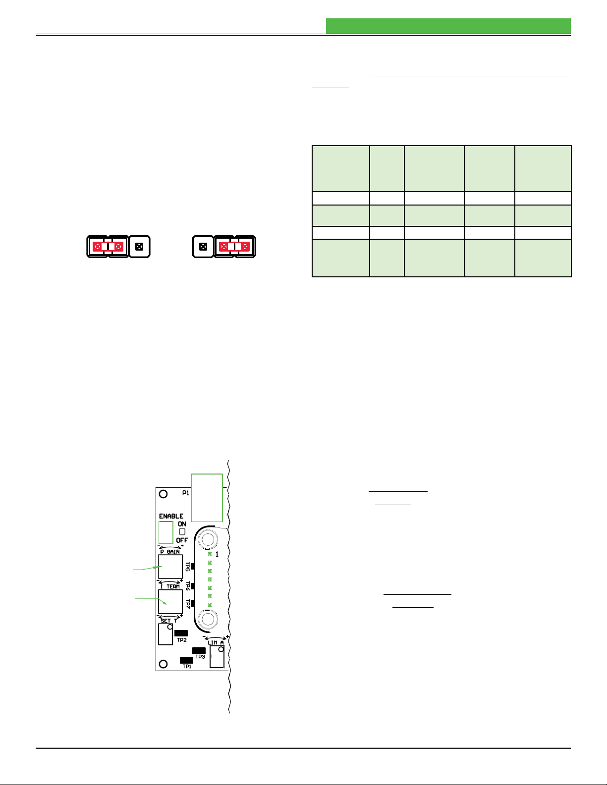
prototyping and benchtop applications the temperature
setpoint can be adjusted with the onboard trimpot on the
evaluation board. When the controller is integrated into an
automated control system, the temperature setpoint can
• Local Enable on WTC3293 Evaluation Board: the
on whenever power is applied to the unit.
• Control loop: the controller employs a smart Proportional-
Integrating control loop to adjust the drive current. The
proportional term is user-adjustable, and when properly
minimal overshoot and ringing.

© 2022 www.teamWavelength.com 12
WTC3243 TEMPERATURE CONTROLLER
CONFIGURE THE JUMPERS & SWITCH
On the underside of the WTC3293 Evaluation Board you
Figure 5 below to
locate them.
Figure 5. Bottom View, Jumper Locations -- Factory Default
SET THE POWER SELECT JUMPER
VSdrives the output stage while VDD powers the
control electronics. Figure 5 shows the jumper location and
Figure 6 shows the jumper position. The factory default is
to separate the VSand VDD power supply inputs.
• To use Single Supply Operation, place the jumper in the
VS+ VDD or “1” position. Note that when in this position,
VSon the input terminal block pin will be at the same
potential as the VDD pin.
• To use Dual (separate) Supply Operation, place the
jumper in the VDD or “2” position.
1
V
S+ VDD
2
Dual (separate) Supply Operation
Factory Default
1
V
S+ VDD
2
Single Supply Operation
Figure 6. Power Select Jumper Settings
OPERATING INSTRUCTIONS —
WTC3243 + EVAL BOARD
WTC3243 WITH WTC3293 EVAL BOARD
Operate the WTC3243 quickly using the WTC3293
Evaluation Board. For integrating the WTC3243 into
a custom printed circuit board, see Design Guide —
WTC3243 on page 20.
NECESSARY EQUIPMENT
The following equipment is the minimum necessary to
• WTC3243 Temperature Controller
• WTC3293 PCB evaluation board
• Digital multimeter, 4-½ digit resolution recommended
• Thermistor or other temperature sensor
• Peltier-type thermoelectric module or resistive heater
• Optional: test load
• Minimum 22 gauge wiring
• Power Supplies (see below)
• Thermal Solutions Kit, if operating above 5 V or 500 mA
•
SYSTEM DESIGN DECISIONS
several decisions must be made:
• What sensor is being used?
• What bias current is needed?
•
voltage?
• Will the power supply be a single or dual supply?
•
Operating Area (SOA)?
POWER SUPPLY REQUIREMENTS
The VDD power supply is used to power the WTC3243
internal control electronics and must be capable of sourcing
a minimum of 8 mA of current. If a fan is needed, the fan
draw current on VDD will also need to be added to the
minimum required current.
VS
to provide 1.1 times quiescent current and TEC current.
VS= 1.1 * (ITEC + VS_QUIESCENT)
For VS, when selecting a power supply, choose a voltage
as close to the operating voltage of the TEC as possible to
dissipation.
SENSOR BIAS SWITCH
(100 µA shown)
VSET SOURCE JUMPER
(use onboard trimpot shown)
POWER SELECT JUMPER
(separate supplies shown)
SENSOR GAIN JUMPER
(GAIN = 1 shown)

© 2022 www.teamWavelength.com 13
WTC3243 TEMPERATURE CONTROLLER
SET THE VSET SOURCE JUMPER
Figure 7 shows the jumper positions and Figure 8 shows
the jumper location.
• To use the onboard trimpot to generate the setpoint
voltage (VSET), move the jumper to the trimpot or “T”
position.
•
or “X” position.
• To use the high voltage setpoint (HSET) input, completely
remove the jumper. Using the HSET setting bypasses
the Data Acquisition Failsafe Protection circuit.
NOTE: When the VSET SOURCE jumper is in the “X”
position or removed, the voltage dialed in using the SET T
trimpot on the WTC3293 is ignored.
XX X TT T
RSET is Source HSET is Source
Trimpot is Source
(Factory Default)
Figure 7. VSET Source Jumper Settings
SET THE SENSOR BIAS SWITCH
Use Table 4
temperature sensor type. Sensor signal at SEN+ (TB4)
DD - 2 V). The minimum recommended
Figure 8 shows the switch location.
Figure 8. Sensor Bias Switch & VSET Jumper Location
Table 4.
SENSOR TYPE 1 mA 100 µA 10 µA
(with Sensor Gain = 10) OFF ON OFF
ON
1 2 3
Thermistor OFF ON OFF
ON
1 2 3
Thermistor OFF OFF ON
ON
1 2 3
ON OFF OFF
ON
1 2 3
LM335
(with Sensor Gain = 10) ON OFF OFF
ON
1 2 3
AD590
wiring diagram)
OFF OFF OFF
ON
1 2 3
Black indicates switch head position.
SENSOR BIAS SWITCH
(100 µA shown)
VSET SOURCE JUMPER
(use onboard trimpot shown)
SENSOR GAIN JUMPER
(GAIN = 1 shown)

© 2022 www.teamWavelength.com 14
WTC3243 TEMPERATURE CONTROLLER
SET THE SENSOR GAIN JUMPER
The Sensor Gain Jumper allows the user to amplify sensor
voltage. The minimum recommended signal is 250 mV in
Figure 8 shows the
jumper location and Figure 9 shows the jumper position.
• If the sensor voltage is in the acceptable range, use
the 1X position and the sensor signal will pass through
• If the sensor voltage is very low, such as when using
move the jumper to the 10X position to amplify the
sensor feedback signal by a factor of ten.
• DD - 2V.
1X 10X
GAIN GAIN
Factory Default
Figure 9. Sensor Gain Jumper Settings
SET THE PROPORTIONAL GAIN AND
INTEGRATOR TIME CONSTANT
NOTE: This step must be done without the WTC3243
installed to allow for accurate resistance readings. The
Proportional Gain (P GAIN) and Integrator Time Constant
(I TERM) can be adjusted during operation, but resistance
readings will not match the table if the WTC3243 is installed.
P GAIN
I TERM
Figure 10. Location of the P GAIN and I TERM Trimpots
Table 5 suggests starting points for P GAIN and I TERM
depending on your sensor type. To optimize control, refer
to Tech Note TN-TC01: Optimizing Thermoelectric Control
Systems.
Table 5. Proportional Gain and Integrator Time Constant
Starting Suggestions
SENSORTYPE P GAIN
P GAIN
TRIMPOT
RESISTANCE
P
TP5 & TP6
I TIME
CONSTANT
TC
I TERM
TRIMPOT
RESISTANCE
I
TP6 & TP7
Thermistor 10 3 seconds
RTD 50 1 second
LM335 25 2 seconds
AD590
resistor across
Sen+ and Sen-)
25 2 seconds
To adjust the P GAIN, use an ohmmeter to measure
resistance between Test Points 5 and 6 (TP5 & TP6).
Adjust the P GAIN trimpot to the desired resistance; see
Table 5 for suggested starting points. An online design
calculator is available to assist in determining resistance
values.
www.teamwavelength.com/support/design-tools/wtc-calculator/
Or use Equation 1 to calculate the P GAIN trimpot
resistance.
Equation 1. Calculating RPfrom P GAIN
R
P
=
(
100,000
)
[Ω]
100 - 1
PGAIN
Equation 2. Calculating P GAIN from RP
PGAIN =
(
100
)
[A / V]
100,000 + 1
R
P
Where:
RP
PGAIN is in Amps / Volts (A / V)

© 2022 www.teamWavelength.com 15
WTC3243 TEMPERATURE CONTROLLER
To adjust the I TERM, use an ohmmeter to measure resistance
between Test Points 6 & 7 (TP6 & TP7).
Adjust the I TERM trimpot to the desired resistance, see
Table 5 for suggested starting points. An online design
calculator is available to assist in determining resistance
values.
www.teamwavelength.com/support/design-tools/wtc-calculator/
Or use Equation 3 to calculate the I TERM trimpot resistance.
Equation 4 shows how to calculate the I TERM, given the
trimpot resistance.
Equation 3. Calculating RIfrom ITC
R
I
=
(
100,000
)
[Ω]
(1.89) I
TC
- 1
Equation 4. Calculating ITC from RI
I
TC
= (0.53)
(
100,000
+ 1
)
[Seconds]
R
I
Where:
RI
ITC is in seconds
INSTALL THE WTC3243 ON THE WTC3293
EVALUATION BOARD
USE
WITH
WTC3243
Temperature
Controller
ONLY
WAVELENGTH
ELECTRONICS
Figure 11. WTC3243 Installed on WTC3293 Eval Board
1. Match up the notch on the WTC3243 with the silkscreen
on the PCB.
2. Align the pins with the sockets, ensuring that all pins are
lined up in their respective sockets.
3. Make sure that
none of the pins were bent during insertion before
continuing.
4.
strength to secure the WTC to the circuit board. Install
the WTC3243 heat spreader. Choose opposite corners
that will not interfere with fan mounting.
5. Figure 12. WTC3293
.
.
!

© 2022 www.teamWavelength.com 16
WTC3243 TEMPERATURE CONTROLLER
4-40 x 0.625”
nylon standoffs
(four provided)
Figure 12.
ATTACH THE HEATSINK & FAN
The WTC3243 is designed to handle currents as high
as 2.2 A and installing a heatsink and fan is optional
when using less than +5 V or 500 mA during operation.
A heatsink and/or fan is mandatory when driving currents
higher than 500 mA or operating above +5 V.
Refer to the online SOA calculator to determine the Safe
Operating Area and proper thermal solution for your
application. Wavelength’s temperature controller SOA
calculator is found here:
www.teamwavelength.com/support/design-tools/wtc-calculator/
Follow Figure 13 to assemble the heatsink and fan to the
temperature controller.
Actual fan wire configuration may be different than
shown.
Fan can be rotated on the WTC so the location of the
wires matches your PCB.
Screw: 4-40 PHPH
(x 0.75” w/o FAN)
(x 1” with FAN)
30 mm FAN
WXC303 (+5 VDC) or
WXC304 (+12 VDC)
WHS302 Heatsink
WTW002
Thermal Washer
WTC3243 Heat Spreader
Air Flow
Figure 13. Attaching the WEV Thermal Components
Clean all of the mating surfaces on the WTC electronics
component and heatsink. It is important that no particulates or
foreign matter are on either surface.
Attach the adhesive side of the thermal washer to the bottom
of the heatsink, aligning the washer holes with the heatsink
holes.
If a fan is required, align the fan with the heatsink. The direction
Attach the heatsink and fan assembly to the temperature
controller heat spreader, using two screws.
Connect the fan leads to Terminal Block 2 (TB2), securing
FAN (+) and the black wire to FAN (-).
The fan connects to the VDD supply, not VS, so be sure that the
correct voltage fan is selected, either +5 VDC or +12 VDC.

© 2022 www.teamWavelength.com 17
WTC3243 TEMPERATURE CONTROLLER
ATTACH THE VDD AND VS POWER SUPPLIES
The VDD power supply is used to power the WTC3243
internal control electronics and must be capable of
sourcing a minimum of 8 mA of current. If a fan is needed,
the fan draw current on VDD will also need to be added
to the minimum required current. The VSpower supply is
used to power the WTC3243 output stage and must be
capable of supplying a current greater than the Limit A
(LIMA) and Limit B (LIMB) current limit settings.
For simple operation, set the Power Supply Jumper to “1”
or Single Supply Operation (see Figure 6) and then use
the power jack. The power jack is tied to VDD. To separate
the supplies, set the Power Jumper to “2” or Dual Supply
Operation and use either the terminal block (TB1) alone
or a combination of the power jack and VS on TB1.
Use PGND for the power return. The common (COM)
terminal on the WTC3293 is not intended to act as a
power connection, but as a low noise ground reference
for monitor signals.
A separate power supply allows the output stage to
operate at a voltage lower than the VDD supply or up to the
S
Output B (OUTB), which is also the voltage across the
thermoelectric controller, to reduce the power dissipation
on the WTC3243 component and minimize the heatsinking
requirements. When sizing the power supply, take the
temperature controller, load, and heatsink components
into consideration.
The 2.5 mm input power jack is attached to VDD. You can
use the Wavelength PWRPAK power supplies with this
jack. Use either the power jack or the power inputs on
TB1, not both.
CONFIGURE THE HEAT AND COOL LIMITS
The WTC3293 Limit A (LIMA) and Limit B (LIMB) trimpots
independently adjust the heat and cool current limits from
zero to a full 2.2 A.
Use Equation 5 to calculate the voltage at LIMA or LIMB
corresponding to the desired limit current (ILIM).
Equation 5. Calculating LIMA or LIMB from ILIM
LIM = (0.3 * ILIM) + 1
Where:
LIMA or LIMB is in Volts (V)
ILIM
Once the LIMA and LIMB values are determined, toggle
the ENABLE to ON to apply power to VDD and VS(no load
required). Rotate LIMA or LIMB trimpot and monitor the
respective voltage at LIMA and LIMB on TB3. Use COM as
ground reference. Turn the trimpots counter-clockwise to
reduce the limits or clockwise to increase them.
Use Table 6 to determine which limit trimpot sets the heating
and cooling limits based on the sensor and load type.
Table 6. LIMA and LIMB Current Limit Trimpot Function
SENSOR TYPE LOAD TYPE LIMA
TRIMPOT
LIMB
TRIMPOT
Thermistor Thermoelectric Cool Current
Limit
Heat Current
Limit
RTD, LM335,
AD590
Thermoelectric Heat Current
Limit
Cool Current
Limit
Thermistor Resistive Heater Turn Fully
CCW
Heat Current
Limit
RTD, LM335,
AD590
Resistive Heater Heat Current
Limit
Turn Fully
CCW
!
!

© 2022 www.teamWavelength.com 18
WTC3243 TEMPERATURE CONTROLLER
CONNECT THE TEMPERATURE SENSOR AND
THERMAL LOAD OR A TEST LOAD
With the ENABLE switch set to OFF (output is disabled),
connect the load (the thermoelectric cooler or resistive
heater) to the outputs (OUTA or OUTB). Use Table 7 to
determine the connections to the outputs.
Table 7.
SENSOR TYPE LOAD TYPE OUTPUT A
OUTPUT B
NTC Thermistor Thermoelectric Negative TEC
Terminal
Positive TEC
Terminal
RTD, LM335,
AD590
Thermoelectric Positive TEC
Terminal
Negative TEC
Terminal
NTC Thermistor Resistive Heater
Quick Connection: Connect
the resistive heater to OUTA
and OUTB. Adjust the cooling
current limit to zero by turning
the LIMA trimpot fully CCW.
Connection: Connect one side
of the heater to OUTB and the
other to the voltage source VS.
RTD, LM335,
AD590
Resistive Heater
Quick Connection: Connect
the resistive heater to OUTA
and OUTB. Adjust the cooling
current limit to zero by turning
the LIMB trimpot fully CCW.
Connection: Connect one side
of the heater to OUTA and the
other to the voltage source VS.
Resistive temperature sensors and LM335 type temperature
sensors should connect their negative termination directly
to Pin 13 (GND) to avoid parasitic resistances and voltages
Connect thermistors and RTD sensors, which are not
polarized, to SEN+ and SEN- on Terminal Block 4 (TB4).
Connect LM335 and AD590, which are polarized, as shown
below.
LM335
SEN+
SEN-
AD590
VDD
SEN+
SEN-
10 kΩ
Figure 14. Connecting IC Temperature Sensors
MONITOR THE SETPOINT TEMPERATURE AND
ACTUAL TEMPERATURE SENSOR VOLTAGE
monitoring the WTC3243 temperature setpoint voltage
(SET T) and the actual temperature sensor voltage levels
(ACT T). Both the SET T and ACT T voltages are measured
from the COMMON (COM) terminal.
Convert the monitor voltages to sensor resistance for
thermistors and RTDs, and to temperature for LM335s and
AD590s using the following equations.
Table 8. Converting the SET T and ACT T Monitor Voltages
SENSOR TYPE VOLTAGE CONVERSION
Thermistor
(where Sensor Gain is 10)
LM335 or AD590
* Voltage refers to the measurements made from the
ACT T or SET T points, in Volts (V). Sensor Bias Current
is in Amps (A).
Figure 15. WTC3293 Evaluation Board & Voltmeter
To read the ACT T, attach the voltmeter to the ACT T and
COM wires.
To read the SET T, attach the voltmeter to the SET T and
COM wires.
R =
(
Voltage*
)
[Ω]
Sensor Bias Current
R =
(
Voltage*
)
/ 10 [Ω]
Sensor Bias Current
T = (Voltage* - 2.7315) * 100 [ºC]
USE
WITH
WTC3243
Temperature
Controller
ONLY
WAVELENGTH
ELECTRONICS
DMM

© 2022 www.teamWavelength.com 19
WTC3243 TEMPERATURE CONTROLLER
ADJUST THE TEMPERATURE SETPOINT
VOLTAGE
The setpoint voltage can be adjusted either by using the
evaluation board’s onboard SET T trimpot or by connecting
a remote voltage source or potentiometer to the RSET or
HSET inputs. Only one of these setpoints can be used.
When controlling correctly, the SET T matches the ACT T at
the desired temperature.
The setpoint voltage can also be adjusted using the
evaluation board by connecting a remote voltage source
or potentiometer to the remote setpoint (RSET) or the high
voltage setpoint (HSET) inputs.
To adjust the SET T, with the voltmeter attached to the
SET T and COM wires, turn the SET T trimpot screw. Rotate
the trimpot clockwise to increase or counter-clockwise to
decrease the voltage. The SET T trimpot can be adjusted
from 0 V to 5 V. To get above 4.5 V, increase VDD to a
minimum of 5.5 V. To read the actual temperature and
setpoint temperature of the device, the power needs to be
connected.
NOTE: If you are not getting a setpoint reading, make sure
your VSET jumper is set correctly.
• The RSET input is subject to the Data Acquisition
(DAQ) Failsafe Protection circuit. If RSET drops below
0.3 V, the setpoint will be overridden and set to 1 V. See
the Additional Technical Notes section for changing
these defaults. RSET is limited to 0 to 6.5 V.
• The HSET remote setpoint input is not subject to the
DAQ Failsafe Protection circuit. It is limited to 0 to
(VDD – 2.5 V).
ENABLE AND DISABLE THE OUTPUT CURRENT
Toggle the ENABLE switch to ON. Output is enabled when
the green LED light is on. If there is no power to VS, the LED
will not light.
remote enable (REN) on TB2 can be used.
0 V = ENABLE
Floating or >3 V = DISABLED

© 2022 www.teamWavelength.com 20
WTC3243 TEMPERATURE CONTROLLER
DESIGN GUIDE — WTC3243
NECESSARY EQUIPMENT
The following equipment is the minimum necessary to
• WTC3243 Thermoelectric Controller
• Digital multimeter, 4-1/2 digit resolution recommended
• Custom Printed Circuit Board (PCB)
• Thermistor or other temperature sensor
• Peltier-type thermoelectric module or resistive heater
• Power supply or supplies
•
circuit, etc.)
• 5 to 6 Resistors for Limits (2), P GAIN, Integrator Time
Constant, Sensor Bias Current, Sensor Gain (optional)
• Thermal Solutions Kit, if operating above 5 V or 500 mA
SAFE OPERATING AREA AND THERMAL
DESIGN CONSIDERATIONS
SOA charts are included in this datasheet for quick
reference, but we recommend you use the online tools
instead. Refer to the SOA calculator for the WTC3243.
www.teamwavelength.com/support/design-tools/soa-tc-calculator/
TO ENSURE SAFE OPERATION OF THE WTC3243
CONTROLLER, IT IS IMPERATIVE THAT YOU DETERMINE
IF THE UNIT IS GOING TO BE OPERATING WITHIN THE
INTERNAL HEAT DISSIPATION SAFE OPERATING AREA
(SOA).
DESIGN CONSIDERATIONS WHEN USING THE
WTC3243 WITHOUT THE WTC3293 BOARD
The WTC3243 Thermoelectric Controller is designed to
be integrated into any custom printed circuit board (PCB)
The following equations for resistors are incorporated in the
WTC3243 Circuit Design Calculator online at:
www.teamwavelength.com/support/design-tools/wtc-calculator/
on the subsequent pages. Equations from the calculator
follow the wiring diagrams.
!
Other manuals for WTC3293
1
This manual suits for next models
2
Table of contents
Other Wavelength Electronics Motherboard manuals

Wavelength Electronics
Wavelength Electronics WTC32ND User manual

Wavelength Electronics
Wavelength Electronics WLD33ND User manual

Wavelength Electronics
Wavelength Electronics WLD3343 User manual

Wavelength Electronics
Wavelength Electronics WLD3393 User manual

Wavelength Electronics
Wavelength Electronics WTC3243 User manual

Wavelength Electronics
Wavelength Electronics WLD3393 User manual