www.teamwavelength.com© 2001, 2003, 2009
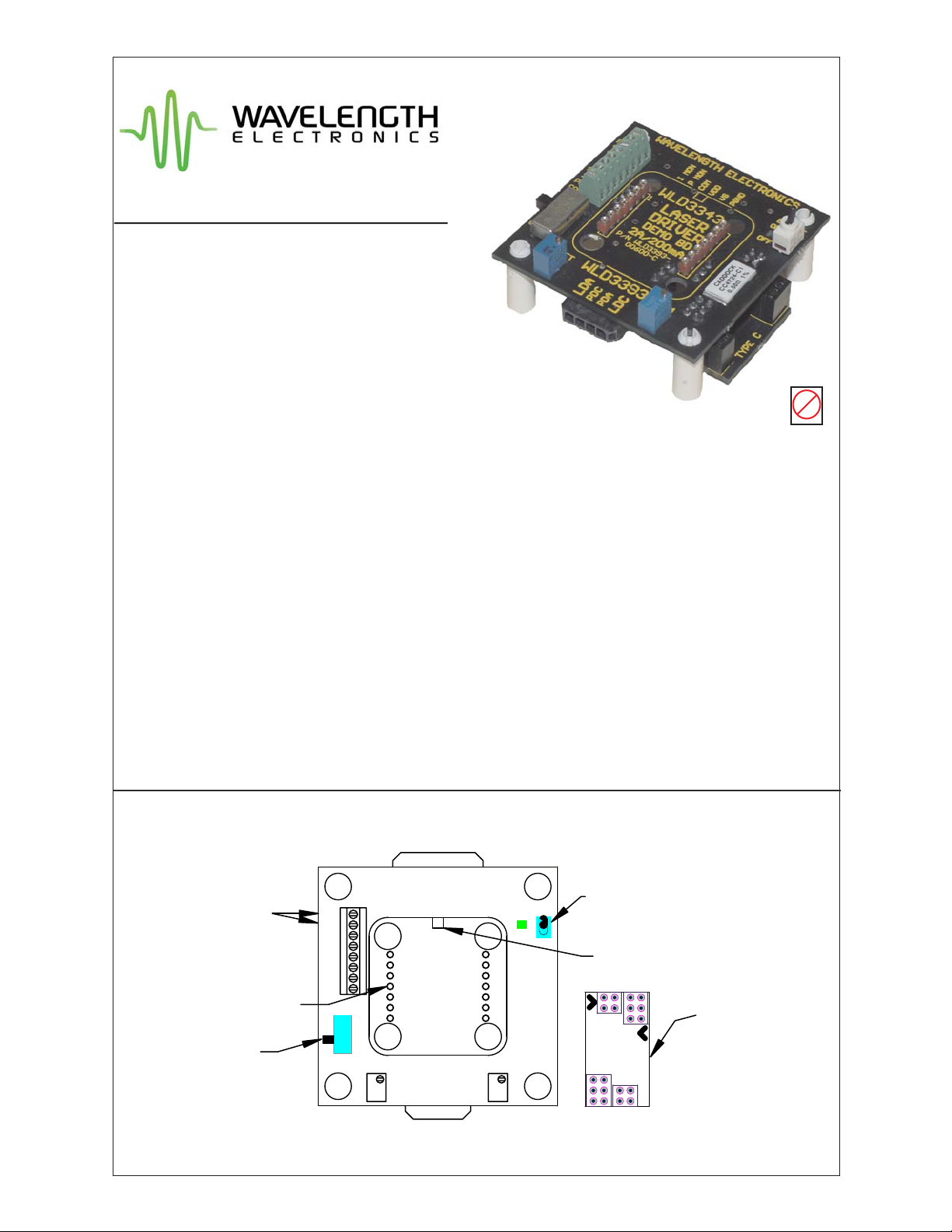
WLD3393
PAGE 11
WLD3393-00400-A Rev F
NOTICE:
The information contained in this document is
subject to change without notice. Wavelength
will not be liable for errors contained herein
or for incidental or consequential damages in
connection with the furnishing, performance, or
use of this material. No part of this document
may be photocopied, reproduced, or translated to
another language without the prior written consent
of Wavelength.
SAFETY:
There are no user serviceable parts inside
this product. Return the product to Wavelength
for service and repair to ensure that safety fea-
tures are maintained.
LIFE SUPPORT POLICY:
As a general policy, Wavelength Electronics, Inc.
does not recommend the use of any of its products
in life support applications where the failure or
malfunction of the Wavelength product can be
reasonably expected to cause failure of the life
support device or to significantly affect its safety
or effectiveness. Wavelength will not knowingly
sell its products for use in such applications
unless it receives written assurances satisfactory
to Wavelength that the risks of injury or damage
have been minimized, the customer assumes all
such risks, and there is no product liability for
Wavelength. Examples of devices considered to be
life support devices are neonatal oxygen analyzers,
nerve stimulators (for any use), auto transfusion
devices, blood pumps, defibrillators, arrhythmia
detectors and alarms, pacemakers, hemodialysis
systems, peritoneal dialysis systems, ventilators of
all types, and infusion pumps as well as other
devices designated as “critical” by the FDA. The
above are representative examples only and are not
intended to be conclusive or exclusive of any other
life support device.
CERTIFICATION AND WARRANTY
CERTIFICATION:
Wavelength Electronics, Inc. (Wavelength) certifies
that this product met it’s published specifications at the
time of shipment. Wavelength further certifies that its
calibration measurements are traceable to the United
States National Institute of Standards andTechnology,
to the extent allowed by that organization’s calibration
facilities, and to the calibration facilities of other
International Standards Organization members.
WARRANTY:
This Wavelength product is warranted against defects
in materials and workmanship for a period of 90 days
from date of shipment. During the warranty period,
Wavelength will, at its option, either repair or replace
products which prove to be defective.
WARRANTY SERVICE:
For warranty service or repair, this product must
be returned to the factory. An RMA is required
for products returned to Wavelength for warranty
service. The Buyer shall prepay shipping charges
to Wavelength and Wavelength shall pay shipping
charges to return the product to the Buyer upon
determination of defective materials or workmanship.
However, the Buyer shall pay all shipping charges,
duties, and taxes for products returned to Wavelength
from another country.
LIMITATIONS OF WARRANTY:
The warranty shall not apply to defects resulting from
improper use or misuse of the product or operation
outside published specifications.
No other warranty is expressed or implied.Wavelength
specifically disclaims the implied warranties of
merchantability and fitness for a particular purpose.
EXCLUSIVE REMEDIES:
The remedies provided herein are the Buyer’s sole
and exclusive remedies. Wavelength shall not be
liable for any direct, indirect, special, incidental, or
consequential damages, whether based on contract,
tort, or any other legal theory.
WAVELENGTH ELECTRONICS, INC.
51 Evergreen Drive
Bozeman, Montana, 59715
web: www.teamwavelength.com
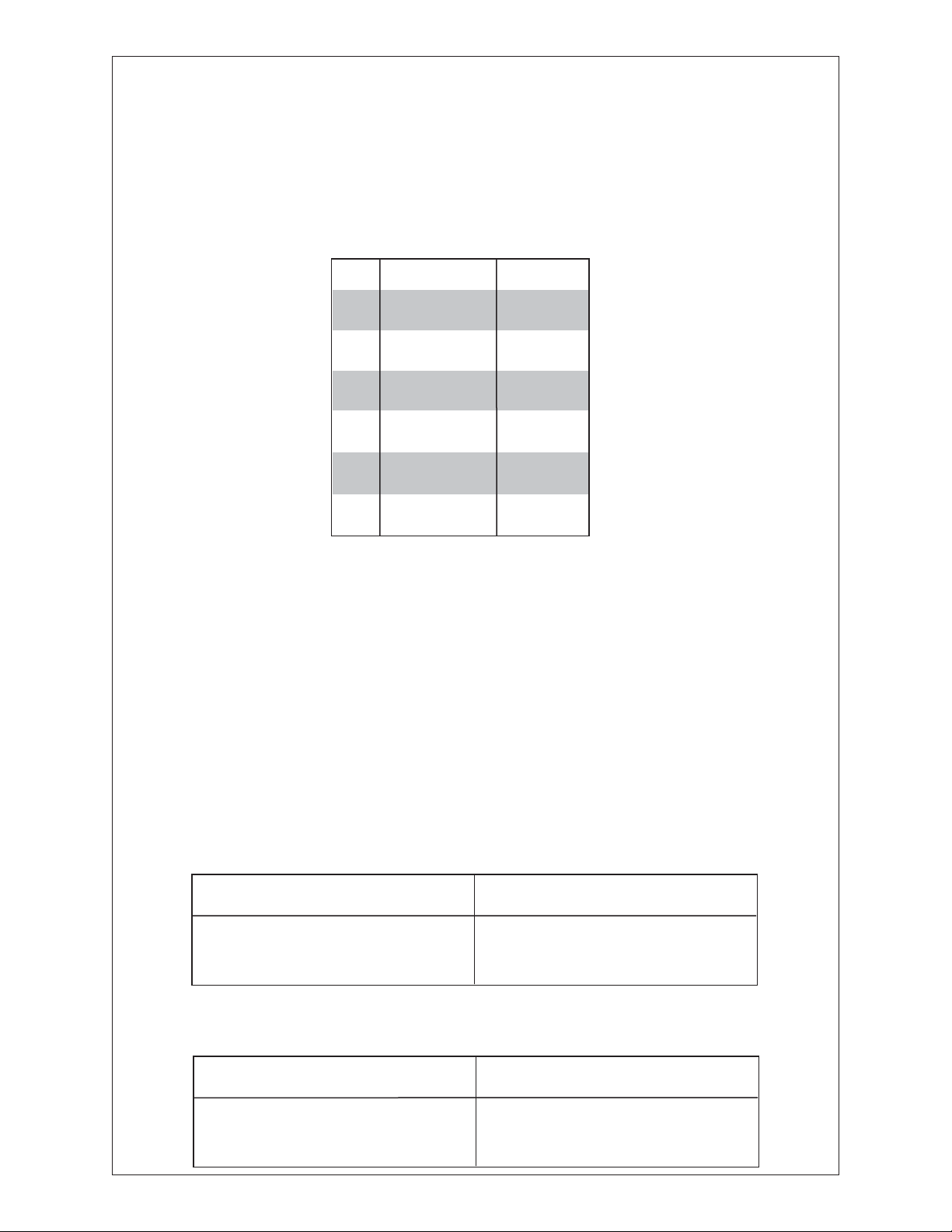
REVISION HISTORY
REVISION
REV. E
REV. F
DATE
Oct-03
31-Aug-09
NOTES
Initial release
Updated links to support new
website
phone: (406) 587-4910 Sales/Tech Support
fax: (406) 587-4911