INTRODUCTION SMARTSENSOR ADVANCE USER GUIDE 9
sition the sensor to avoid detection of turn-only lanes. Consider using speed lters to
remove the impact of turning vehicles.
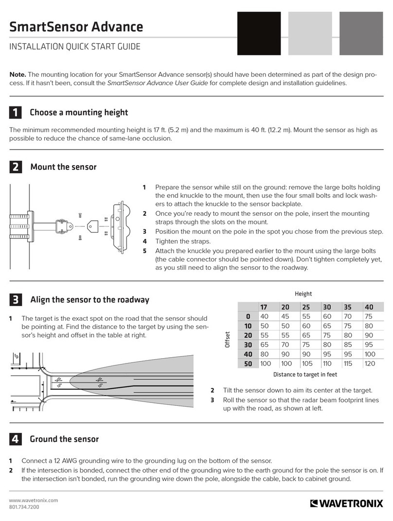
Mounting Height – Mounting the sensor as high as possible is recommended to reduce
same lane occlusion. A maximum of 40 ft. (12.2 m) and minimum of 17 ft. (5.2 m) is
recommended. If the sensor is higher than 30 ft. (9.1 m), the oset should be less than
50 ft. (15.2 m) to increase accuracy.
Mounting Oset – Mounting the sensor closer to the lanes of interest will usually in-
crease detection accuracies. A maximum oset of 50 ft. (152.4 m) is recommended, but
the sensor will still reliably track vehicles at further osets. Mounting with a smaller
oset will generally increase line-of-sight.
Cable Length – Make sure that you have sucient homerun and sensor cabling. With
the newer models, cable runs as long as 1500 ft. (457.2 m) are achievable using 24
VDC operation and RS-485 communications. Older models supported up to 600 ft.
(182.9 m). Consult Appendix B for more information.
Suspended Electrical Cables –e sensor is designed to work in the presence of
suspended power lines and other electrical cabling, however these cables should be
mounted at least ten feet away from the front of the sensor.
Neighboring Structures and Parallel Walls – For best performance, it is preferred that
the sensor be mounted without signs or other at surfaces mounted directly behind it.
is will help reduce multiple reection paths from a single vehicle.
e SmartSensor Advance should be mounted using one of the following options (see
Figure I.1):
1 On a vertical pole – e preferred mounting location for the SmartSensor Advance or
SmartSensor Advance Extended Range is often a vertical pole near the stop bar. Verti-
cal poles are typically installed on the roadside of the approach near the stop bar to
support a mast arm, span wire or luminaire. ese poles often extend as high as 30 ft.
(9.1 m) or more, allowing the sensor to be mounted high enough to reduce occlusion.
is mounting location is typically very safe for installation.
2 On a luminaire – is mounting location will often reduce the oset and increase the
mounting height (a maximum of 40 ft. (12.2 m) is recommended). Make sure the
luminaire can support the load of the sensor. is mounting location is typically very
safe for installation.
3 The backside of the opposing mast arm – By mounting on the backside of the mast
arm, opposite the signal heads for the opposing direction of travel, the sensor can be
placed near the lanes of interest. e minimum mounting height is 17 ft. (5.2 m), but
higher mounting is recommended to minimize occlusion.When appropriate, a vertical
extension can be used; the extension should have the ability to freely rotate the sensor
for alignment. e sensor should be mounted as far out on the mast arm as possible to
avoid potential occlusion issues with stopped vehicles in a left-turn pocket.
4 The front side of the mast arm – e sensor can be installed on the mast arm with
the signals for the approach of interest. SmartSensor Advance Extended Range is
recommended at this mounting location, because typically 100 feet or more of the
sensor’s range is used to cross the width of the intersection. For SmartSensor Advance
Extended Range, the eective maximum range of the sensor is still as high as 800 feet
