manuals.online logo
Brands
  1. Home
  2. •
  3. Brands
  4. •
  5. Wavetronix
  6. •
  7. Accessories
  8. •
  9. Wavetronix SmartSensor V User manual

Wavetronix SmartSensor V User manual

Other manuals for SmartSensor V

4

Other Wavetronix Accessories manuals

Wavetronix Click 400 User manual

Wavetronix

Wavetronix Click 400 User manual

Wavetronix SmartSensor Matrix User manual

Wavetronix

Wavetronix SmartSensor Matrix User manual

Wavetronix SmartSensor V User guide

Wavetronix

Wavetronix SmartSensor V User guide

Wavetronix smartsensor advance Datasheet

Wavetronix

Wavetronix smartsensor advance Datasheet

Wavetronix SmartSensor Matrix Datasheet

Wavetronix

Wavetronix SmartSensor Matrix Datasheet

Wavetronix Click 110 User manual

Wavetronix

Wavetronix Click 110 User manual

Wavetronix SmartSensor Matrix User manual

Wavetronix

Wavetronix SmartSensor Matrix User manual

Wavetronix smartsensor advance User manual

Wavetronix

Wavetronix smartsensor advance User manual

Wavetronix SmartSensor V User manual

Wavetronix

Wavetronix SmartSensor V User manual

Wavetronix SmartSensor V Datasheet

Wavetronix

Wavetronix SmartSensor V Datasheet

Wavetronix SmartSensor HD SS 125 User manual

Wavetronix

Wavetronix SmartSensor HD SS 125 User manual

Wavetronix Click 510 User manual

Wavetronix

Wavetronix Click 510 User manual

Popular Accessories manuals by other brands

Quincy lab 140AE-1 operating manual

Quincy lab

Quincy lab 140AE-1 operating manual

HomePro ZIR000 user manual

HomePro

HomePro ZIR000 user manual

DOL 20SCR Technical user guide

DOL

DOL 20SCR Technical user guide

RAB Smart Task installation manual

RAB

RAB Smart Task installation manual

Kemppi KMS 300 quick guide

Kemppi

Kemppi KMS 300 quick guide

Stearns 57,500 Series Installation and service instructions

Stearns

Stearns 57,500 Series Installation and service instructions

iGuzzini TWILIGHT COPENAGHEN manual

iGuzzini

iGuzzini TWILIGHT COPENAGHEN manual

Adelaide Annexe & Canvas Avan Deluxe installation guide

Adelaide Annexe & Canvas

Adelaide Annexe & Canvas Avan Deluxe installation guide

OHAUS 5000 instruction manual

OHAUS

OHAUS 5000 instruction manual

HOME8 WLS1300 quick start guide

HOME8

HOME8 WLS1300 quick start guide

MAXBOTIX MaxSonar quick start guide

MAXBOTIX

MAXBOTIX MaxSonar quick start guide

ioSmart iSmart56 Installation and user guide

ioSmart

ioSmart iSmart56 Installation and user guide

Focusrite Scarlett 18i8 user guide

Focusrite

Focusrite Scarlett 18i8 user guide

Velleman ED38105 user manual

Velleman

Velleman ED38105 user manual

JumpSport SkyBounce user manual

JumpSport

JumpSport SkyBounce user manual

Prima-Temp PRIYA Instructions for use

Prima-Temp

Prima-Temp PRIYA Instructions for use

Tefcold BC85I-BC85I W user manual

Tefcold

Tefcold BC85I-BC85I W user manual

Vaisala WMS302 user guide

Vaisala

Vaisala WMS302 user guide

manuals.online logo
manuals.online logoBrands
  • About & Mission
  • Contact us
  • Privacy Policy
  • Terms and Conditions

Copyright 2025 Manuals.Online. All Rights Reserved.

SmartSensor V
www.wavetronix.com
801.734.7200
QUICK START GUIDE
1Ensure that all necessary components are available
You will need a number of items in order to install your sensor, including but not limited to the items below:
˽Mount bracket and Band-It clamping system
˽Sensor cable and homerun cable
˽Click equipment and pole-mount box
˽Laptop with SmartSensor Manager, downloaded
from wavetronix.com
˽Bucket truck
2Select a mounting height
Use the table to select the mount-
ing height for the sensor based on
the oset from the nearest detec-
tion lane. e range of ideal osets
is highlighted in gray. If possible,
use the height contained in the
second column (Recommended
Mounting Height).
In areas with a lot of truck trac,
consider a higher mounting height
to help mitigate occlusion.
Note. is table is truncated. For a
complete table, refer to the Smart-
Sensor V User Guide.
Oset from first
Detection Lane
(ft/m)
Recommended
Mounting Height
(ft/m)
Minimum
Mounting Height
(ft/m)
Maximum
Mounting Height
(ft/m)
9/ 2.7 12 / 3.7 9/ 2.7 15 / 4.6
15 / 4.6 15 / 4.6 12 / 3.7 18 / 5.5
20 / 6 18 / 5.5 15 / 4.6 20 / 6
25 / 7.6 20 / 6 17 / 5.2 25 / 7.6
30 / 9.1 22 / 6.7 19 / 5.8 30 / 9.1
35 / 10.7 23 / 7 20 / 6 35 / 10.7
40 / 12.2 25 / 7.6 22 / 6.7 40 / 12.2
45 / 13.7 27 / 8.2 23 / 7 45 / 13.7
50–80 / 15–24 30 / 9.1 25 / 7.6 must be < oset
1 Attach the mount bracket to the pole using the straps.
2 Tighten the strap screws partway. e sensor alignment will need to
be ne-tuned later, so keep the straps slightly loose.
3 Attach the sensor to the bracket; the connector at the bottom of the
unit should point towards the ground.
4 Place the lock washers onto the bolts, thread on the nuts and tighten.
3Attach the sensor and mount bracket to the pole
4Align the sensor to the roadway
1 Tilt the sensor down so that the front is aimed at the center of the detection area, as shown below.
2 Adjust the side-to-side angle
as close to perpendicular to
the ow of trac as possible.
5Attach the cable and pole-mount cabinet
To attach the cable to the sensor and the pole:
1 Squeeze about 25% of the silicon dielectric compound into the con-
nector at the base of the sensor. Wipe o any excess.
2 Insert the cable into the connector and twist clockwise until it clicks.
3 To reduce strain, strap the cable to the pole or run it through a con-
duit, leaving a small amount of slack at the top, as shown.
To attach the pole-mount cabinet to the pole:
1 Attach the mounting brackets to the back of the pole-mount box;
thread in the mounting straps.
2 Attach the pole-mount box to the pole using the mounting straps.
3 Run the sensor/homerun cables through the cable grips on the bot-
tom of the pole-mount box.
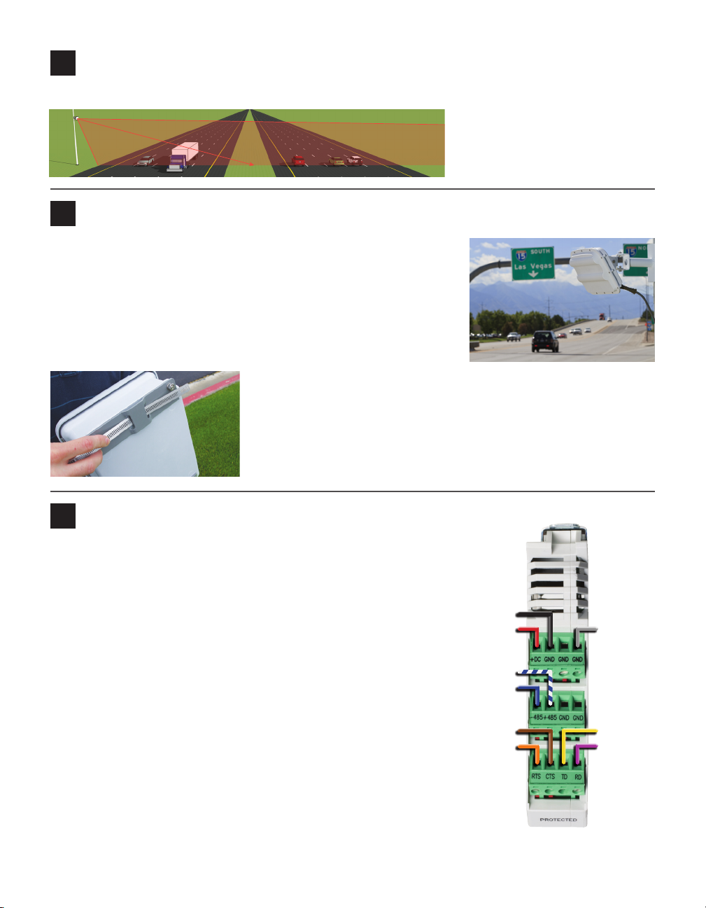
6Connect surge protection and power
Standard Vs use the 8-conductor cable. To land this cable from the
sensor to the Click 200 in the pole-mount cabinet, do the following:
1 Disconnect the Click 200 from the DIN rail.
2 Disconnect the green screw terminals on the appropriate side of
the Click 200 and wire the sensor cable as shown at right.
3 Connect the Click 200 to the DIN rail.
4 Connect the ground terminal to the DIN rail and the earth
ground wire to the lug bolt on the bottom of the pole-mount box.
5 Connect the exterior lug bolt to earth ground.
6 Connect 10–30 VDC to the +DC and –DC terminals on the
appropriate side of the Click 200.
Note. e Click 200 has sides marked PROTECTED and UNPRO-
TECTED; which you use depends on your installation. If you’re un-
sure, consult Chapter 2 of the SmartSensor V User Guide or Wavetro-
nix Technical Services.
This image shows wiring into the protected side, as
you would do if you had an underground cable run
connecting the pole-mount box to a trac cabinet.
-DC (Black)
+DC (Red)
+485 (Stripe)
-485 (Blue)
CTS (Brown)
RTS (Orange)
Drain
TD (Yellow)
RD (Purple)
7Make a connection
Open SmartSensor Manager (SSM) on your laptop to connect to
the sensor:
1 Make a physical or wireless connection to the sensor; gener-
ally you do this via a Click device that has a communication
connection with the sensor—for instance, you could connect
to an Ethernet device on the same T-bus as the Click 200
surge protector the sensor is connected to.
2 Launch SSM and click on the Serial,Modem or Internet
radio button depending on the kind of connection you’re
making.
3 Click OK.
8Enter the sensor settings
Go to Edit > Sensor Settings to access the Sensor Settings. e
Sensor Settings window contains three tabs that allow you to edit
the following settings (if necessary):
˽Serial Number – Text elds for identication
˽Multi-drop ID – Text elds for identication
˽Description/Location – Text elds for identication
˽RF Channel – Prevents radars from interfering
˽Measurement Units – English or Metric
˽Baud Rate – Normally set at 9600 bps
˽Other data collection settings
1 Select Edit > Lane Conguration.
2 Once the Lane Conguration page opens, click on the Auto-
matic button.
3 If you would like to set constraints on the conguration, use
the Edit Range Blinders and Manage Gains buttons (see the
SmartSensor V User Guide for more information).
4 Click the Restart button.
5 Conrm the conguration restart by clicking Yes in the box
that appears. SmartSensor Manager will now automatically
begin detecting and conguring lanes. e conguration
process will take a few minutes, depending on trac ow.
6 Aer the lanes have been detected and congured correctly, save the conguration by clicking the
Finished button.
9Auto-configure the sensor
WX-500-0320
© 2018 Wavetronix LLC. All rights reserved. Protected in the US by patents viewable at www.wavetronix.com/en/legal. Protected by Canadian Patent Nos. 2461411; 2434756;
2512689; and European Patent Nos. 1435036; 1438702; 1611458. Other US and international patents pending. Wavetronix, SmartSensor, Click, Command and all associated logos
are trademarks of Wavetronix LLC. All other product or brand names as they appear are trademarks or registered trademarks of their respective holders. Product specifications are
subject to change without notice. This material is provided for informational purposes only; Wavetronix assumes no liability related to its use.
11 Download interval data
1 Under the Download Interval Data section, click the Browse
button. is will open a directory where you can either create
a new data download le log or locate an existing download
le log.
2 Once you have selected an existing le or created a new le,
click Open.
3 Select the type of download to perform.
˽Normal – Retrieves all interval data.
˽Incremental – Retrieves only interval data recorded aer the
indicated date and time.
˽Error Recovery – Retrieves entire content of ash buer.
4 Once you have selected the type of download, click Download.
1 Go to Data Collection > Setup.
2 Specify the Interval (Bin) size. is setting species the inter-
val of time over which trac variables are aggregated.
3 Check or uncheck the Enabled box. If unchecked, the study
will run only until the sensor’s ash memory is full.
4 Click the Start button to begin the study. As soon as the study
begins, the View Interval Data Buer Status window will ap-
pear showing how much of the onboard storage space is lled
with interval data.
5 To download the data from the study, go to Data Collection
> Download.
10 Set up data collection