manuals.online logo
Brands
  1. Home
  2. •
  3. Brands
  4. •
  5. wavin
  6. •
  7. Construction Equipment
  8. •
  9. wavin Osma OsmaDrain Series User manual

wavin Osma OsmaDrain Series User manual

Quick Guide – Jointing
OsmaDrain 1 of 2
Customer Services:
0844 856 5152
Technical Advice:
0844 856 5165
Website:
www.wavin.co.uk
Email:
technical.design@wavin.co.uk
This Quick Guide is an extract from brochure (ref OD107) Osma Drainage, Product and Installation Manual.
The full document is available for download at www.wavin.co.uk
Preparing Pipe Ends
Pipes cut on site must be clean cut
at right angles to their horizontal axis.
Deburr the cut end with a scraper.
Depth of Entry Mark
Some plain ended fittings have a depth of
entry mark moulded on the spigot. This
depth of entry allows the pipe to expand
into the fitting socket by a minimum of
12mm. Insert the spigot into the socket
until the depth of entry mark is just visible.
All pipes (whether site cut or otherwise)
and other plain ended fittings must be
inserted to the full depth of the socket,
marked at the socket face, and then
withdrawn at least 12mm (See Figure.
10).
Ring Seal Joints
Pipe couplers and most bends and
junctions (in the 110mm and 160mm
sizes) are supplied with sockets on all
ends. These sockets are fitted with ring
seals which act as both a sealing and
expansion joint.
The correct sequence for ring seal jointing
is as follows:
1. Check that the pipe is correctly
prepared (See Pipe preparation,
Figure. 11a) and that the ring seal is
properly seated in its housing.
2. Make sure that both the pipe or fitting
spigot and ring seal socket are dry,
clean and free from grit or dust.
3. Lubricate evenly around the spigot
(NOT the socket) with OsmaDrain
Lubricant (4D392) (See Table 7).
4. Make sure that the components to be
joined are correctly aligned.
5. Push the spigot fully into the socket.
Mark the spigot at the socket face
and then withdraw the spigot by a
minimum of 12mm. If the spigot is
already marked with the depth of
entry, push it into the socket until the
depth of entry mark is just visible.
6. Do not cut back the straight leg
sections of Long Radius Bends
(4D/6D281) as only the spigot end
provided is suitable for jointing.
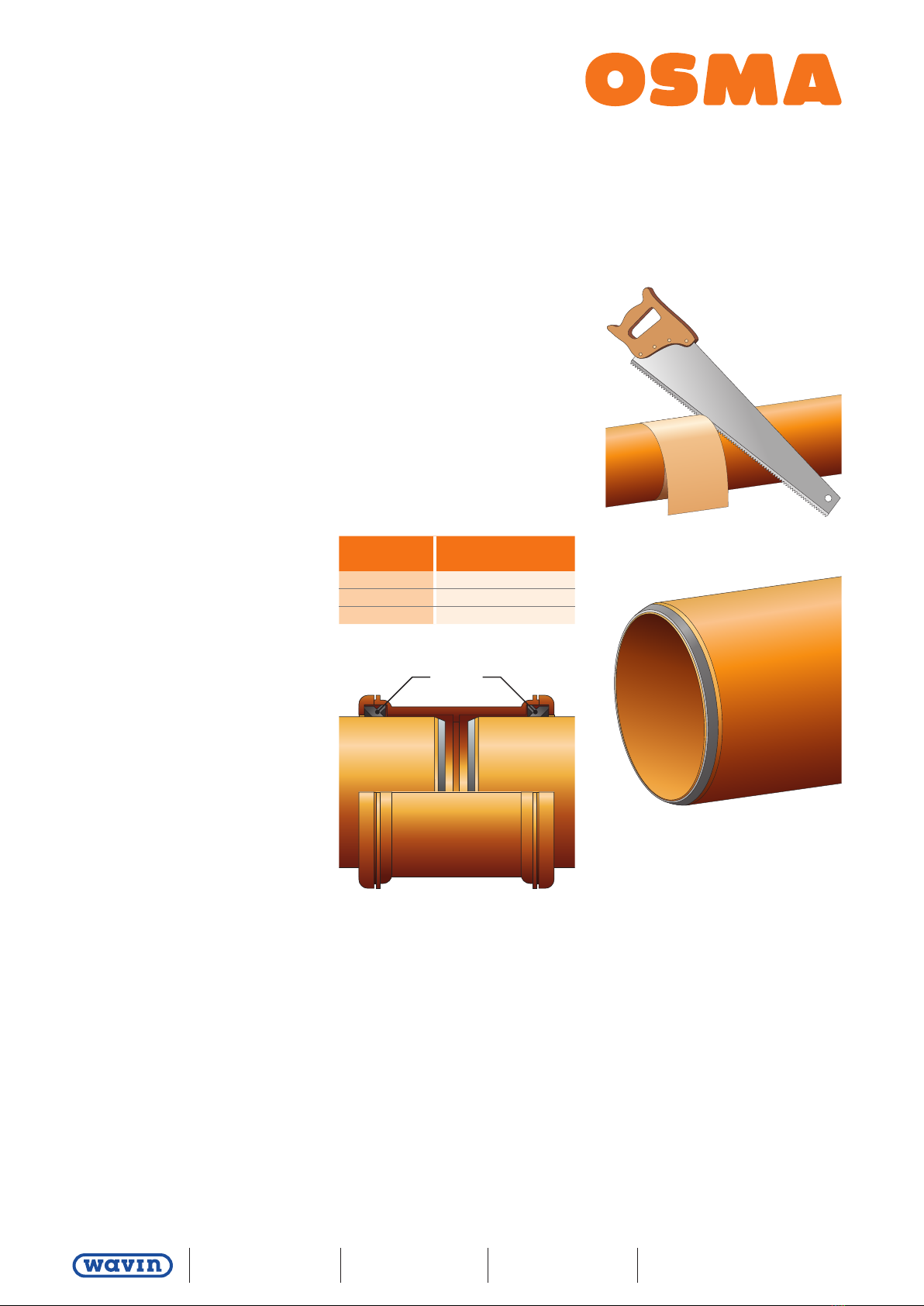
Figure 10: Ring Seal jointing
Figure 11a: Pipe preparation
Figure 11b: Pipe end
Ring Seal
1. Cut pipe square
2. Chamfer and deburr spigot end
Table 7: Lubricant allowance (for
guidance only) weights
Nominal
Size (mm)
Approximate No. of
joints (per 500g)
82 160
110 100
160 45
Quick Guide – Jointing
OsmaDrain 2 of 2
Customer Services:
0844 856 5152
Technical Advice:
0844 856 5165
Website:
www.wavin.co.uk
Email:
technical.design@wavin.co.uk
This Quick Guide is an extract from brochure (ref OD107) Osma Drainage, Product and Installation Manual.
The full document is available for download at www.wavin.co.uk
Solvent Weld Joints
There are relatively few fittings which
need to be solvent jointed. The correct
sequence for solvent jointing is as follows
(also see Figure. 12):
1. Ensure that the pipe has been cut
cleanly and at right angles to its axis.
2. Clean swarf and other dirt from the
pipe end.
3. Wipe the inside of the socket and the
spigot of the pipe or fitting to remove
any surface dirt.
4. To remove grease and prepare
the surfaces of the socket and
spigot, clean both surfaces with
Osma Degreasing Cleaner No 1
(4D380) applied liberally on a clean
nonsynthetic rag or absorbent paper.
5. Apply one coat of Solvent Cement No
2 (4D383) evenly, using a clean brush,
to both the mating surfaces, stroking
the cement along and not around the
surfaces.
6. Immediately insert the spigot straight
into the socket until the full socket
depth is reached, hold for 20–30
seconds and remove any surplus
cement from the mouth of the socket.
7. Each solvent joint must be completed
within 1½ minutes.
8. The joint may be handled after 10
minutes and commissioned after 24
hours.
Do not thin Solvent Cement or Solvent
Cement Filler. As these cements are
solvent based it is essential to observe
the normal precautions for solvents (see
‘Safety’ page 54).
Boss Socket Connections
These may be made on the top of sealed
inspection junction covers using either
a 32mm or 40mm Boss Socket Adaptor
(4S398/399).
Make the connection by drilling out the
unperforated boss socket on the fitting
using a standard 54mm hole cutter.
Solvent weld as described in ’Solvent
Weld Joints’, pushing the adaptor the
full depth along the keyway of the boss
socket.
Figure 12: Solvent Welding – OsmaDrain
Bottle Gully to Pipe spigot
Table 8: Solvent cement allowance
Nominal
Size (mm)
Approximate No. of
joints (per 500g)
82 64
110 44
160 24

Popular Construction Equipment manuals by other brands

Curb Roller Manufacturing BADGER CURB MAKER CM4600 owner's manual

Curb Roller Manufacturing

Curb Roller Manufacturing BADGER CURB MAKER CM4600 owner's manual

Mauldin 650 2021 Operation manual

Mauldin

Mauldin 650 2021 Operation manual

Dobrosfera Z10H Assembly instructions

Dobrosfera

Dobrosfera Z10H Assembly instructions

DK2 Power OPD811 Assembly guide

DK2 Power

DK2 Power OPD811 Assembly guide

probst SRG-UNI-3 operating instructions

probst

probst SRG-UNI-3 operating instructions

Altrad BELLE Operator's manual

Altrad

Altrad BELLE Operator's manual

Toolots W1.2×450 Operation manual

Toolots

Toolots W1.2×450 Operation manual

KRAUSE ProTec XS Instructions for assembly

KRAUSE

KRAUSE ProTec XS Instructions for assembly

Diamond Products CC800M Operator's manual

Diamond Products

Diamond Products CC800M Operator's manual

Stone WolfPac 6100 Operator's manual

Stone

Stone WolfPac 6100 Operator's manual

Toro MMXD-958H-S Operator's manual

Toro

Toro MMXD-958H-S Operator's manual

Komatsu D61EX-12 Operation and maintenance manual

Komatsu

Komatsu D61EX-12 Operation and maintenance manual

HYVA HC1151 user manual

HYVA

HYVA HC1151 user manual

Ammann ARX 23-2 operating manual

Ammann

Ammann ARX 23-2 operating manual

Sealey FDT3.V2 instructions

Sealey

Sealey FDT3.V2 instructions

Strend Pro TCT0504C instruction manual

Strend Pro

Strend Pro TCT0504C instruction manual

Ammann ATR 60 P operating instructions

Ammann

Ammann ATR 60 P operating instructions

Manitowoc National Crane 600H Operator's manual

Manitowoc

Manitowoc National Crane 600H Operator's manual

manuals.online logo
manuals.online logoBrands
  • About & Mission
  • Contact us
  • Privacy Policy
  • Terms and Conditions

Copyright 2025 Manuals.Online. All Rights Reserved.