Multi-Function Remote
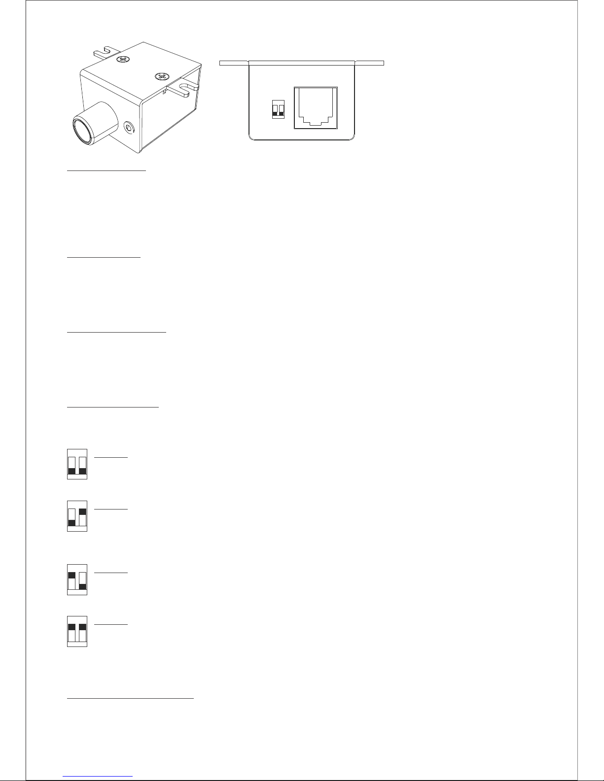
ΠRemote Housing: This 2-piece housing design provides both convenient mounting and simple
dissasembly for customization. The integrated screw mount tabs are scored to aid removal if securing
by another method, and the lower housing can be detatched by removing the two top screws for
reducing weight or size. For panel mounting, the housing can be completely disassembled by also
removing the knob, shaft nut, and circuit board screw. It is recommended to protect the exposed PCB
with heat shrink. For LED relocation, carefully push the LED through from the front to release and
then push out the snap ring from the back to remove. Follow the reverse process for re-mounting.
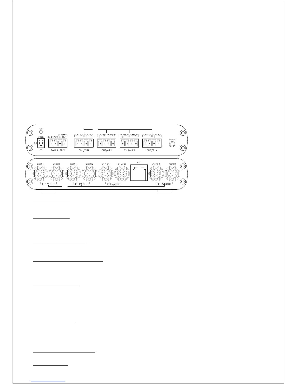
Rotary Encoder: This control knob is for adjusting CH1/2/3/4/5/6/7/8 master volume, CH7/8 level and
source selection (toggle). The factory setting for knob function is CH7/8 output level adjustment only
for a speaker level source. Other knob functions can be enabled via the dip-switches at the back of the
remote (see below). To toggle between Main and AUX sources, short-press the knob. To activate
the selected source’s CH7/8 level mode, long-press for 2 seconds. To reset to factory defaults for the
selected system type, long-press the knob for >5 seconds.
ŽSource/Function LED: Depending upon which system type is selected (see below), this LED will
indicate which source and level mode is currently selected. There are four LED modes: solid red,
flashing red, solid blue and flashing blue. In the default system Type-1, the only LED indication is solid
red when the link8 is powered on. For the other three system types, solid red indicates Main speaker
level source is selected and solid blue is for AUX source. Flashing indicates CH7/8 level mode is active
for the current source, which will timeout after 5 seconds if no adjustments are made.
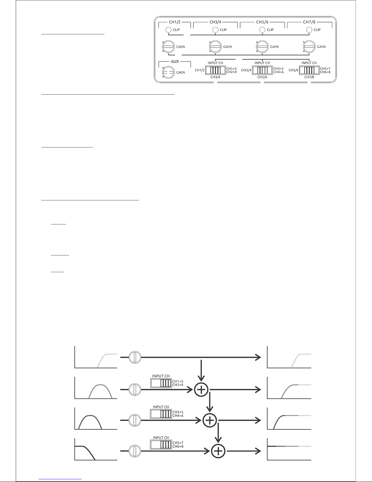
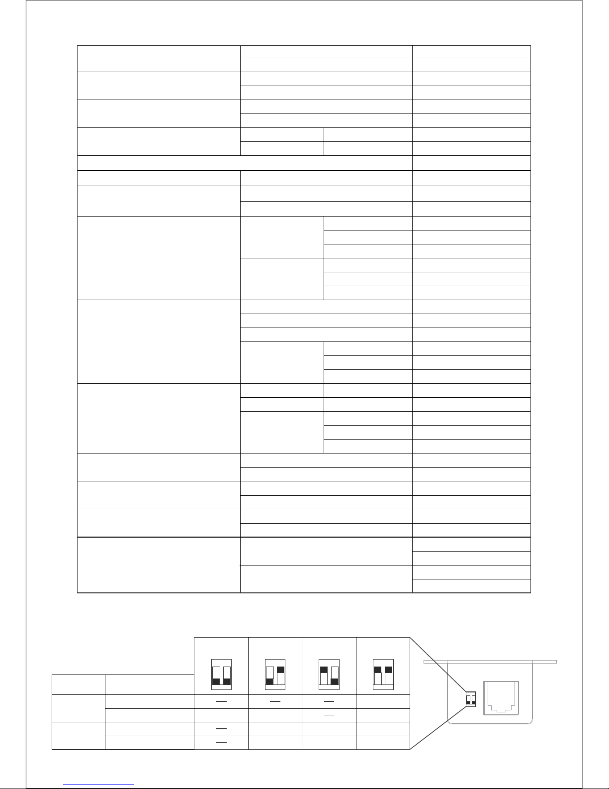
System Type Select: These dip-switches are for selecting one of four available system types for
setting which knob functions and priority are enabled. Note that the up/down position for each switch
is when looking at the back of the remote as shown above. Switch settings can be changed at any time
on the remote without requiring access to the main link8 unit.
Œ
Ž
Type-1: Main CH7/8 Level Only (factory setting)
For systems where only subwoofer level control is needed with a speaker level source, and no
AUX source is connected to the link8. In this setting, the knob’s short-press and long-press
functions (except reset) are disabled to prevent accidental selection.
Type-2: Main CH7/8 Level, AUX Volume & AUX CH7/8 Level
For systems using the factory radio as the master volume for Main speaker level input and an
auxiliary source is connected to the link8’s AUX input. When Main source is selected, the knob
adjusts CH7/8 level only. When AUX source is selected, knob priority is AUX volume and its
CH7/8 level mode can be selected with a 2sec long-press.
Type-3: AUX Volume & AUX CH7/8 Level
For stand-alone applications without a factory radio where only the link8’s AUX input is used as
the system source. In this setting, AUX CH7/8 level mode can be accessed with a 2sec long-press,
while short-press for source select is disabled so cannot be accidentally changed.
Type-4: Master Volume & CH7/8 Level
This setting is primarily for systems where factory radio volume is not used (e.g. fixed input
signal level, volume dependent EQ, etc.), and that may also have an AUX source connected to
the link8. In system Type-4, all knob functions are enabled. When either Main or AUX input is
selected, knob priority is master volume for that source. Independent CH7/8 level adjustment
is also accessable for each source with a 2sec long-press.
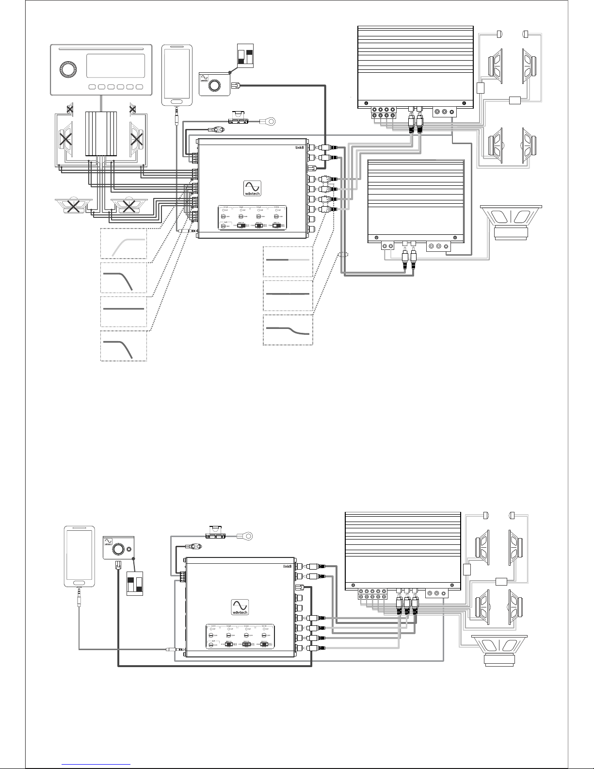
Remote Level Control Jack: This RJ45 jack is for connecting the remote to the RLC port on the main
link8 unit with the supplied cable. A standard 8-conductor ethernet cable may also be used.
Note: The link8 will remember all level settings and which source was selected at last power off and
return at next power on, even if the battery is disconnected. However, if the remote is disconnected at
power on, the memory will be overridden to factory defaults and all levels will return to maximum 0dB.
4