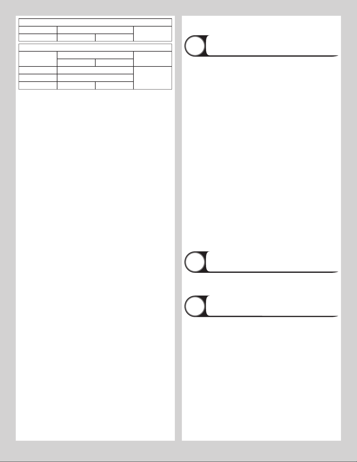
Door Height Spring Length Relaxed (Door
Open)
Spring Length Extended
(Door Closed)
7’ 0” 25” (635 mm) 67” (1702 mm)
7’ 6” 27” (686 mm) 72” (1829 mm)
7’ 9” 27” (686 mm) 73-1/2” (1867 mm)
8’ 0” 27” (686 mm) 75” (1905 mm)
Balancing Door
19
Lift door and check its balance. If door rises off floor more than 2 ft. under spring tension
alone, reduce spring tension by adjusting extension spring length, moving the “S” hook back-
ward (towards the rear back hangs) to a different hole in the horizontal track. If the door is
hard to rise or drifts down on its own, adjust extension spring length by moving the “S” hook
forward (towards the header) to a different hole in the horizontal track. A poorly balanced
door can cause garage door operator problems.
IMPORTANT: WHENEVER ADJUSTING EXTENSION SPRING LENGTH FOR DOOR BALANCE,
ALWAYS OPEN THE DOOR TO THE FULLY OPEN POSITION AND RETURN THE LOCKING
PLIERS, AS SHOWN IN F3 TO THE HORIZONTAL TRACKS BELOW THE BOTTOM TRACK
ROLLERS.
If the door still does not operate easily, raise the door into the open position, return the lock-
ing pliers, and recheck the following items:
1.) Is the door level?
2.) Are the flag angles level and plumb?
3.) Does the distance between the flag angles equal door width plus 3-3/8” to 3-1/2”?
4.) Do the counterbalance lift cables have equal tension? Adjust by re-tieing the special knot,
if necessary.
5.) Make sure door is not rubbing on jambs.
IMPORTANT: IF DOOR STILL DOES NOT BALANCE PROPERLY, THEN CONTACT A TRAINED
DOOR SYSTEM TECHNICIAN.
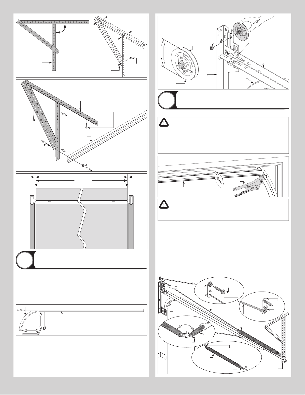
Attaching Weather Seal
20
Permanently attach the weatherstrips on both door jambs and header. The weatherstrips
were temporarily attached in Preparing the Opening, in the pre-installation section of this
manual.
NOTE: When permanently attaching the weatherstrips to the jambs, avoid pushing the weath-
erstrips too tightly against the face of door.
Weather seals
Nail
Weather
Jamb Weather seal
Jamb
Header
Jamb
Nail
NOTE: Door not shown for clarity.
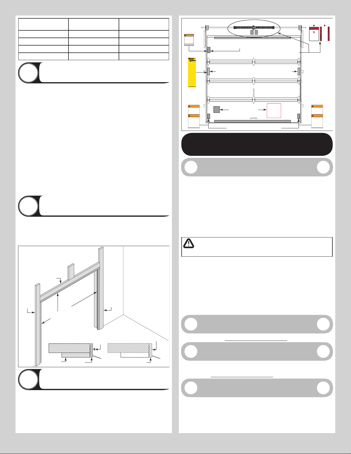
Label Placement
21
IMPORTANT: USING THE ILLUSTRATION, ATTACH THE APPROPRIATE LABELS TO THE AP-
PROPRIATE LOCATION ON THE SECTION, AS SHOWN.
NOTE: The Spring Warning tag(s) are factory attached (one per spring).
NOTE: Because of different configurations, some labels may require minor relocations.
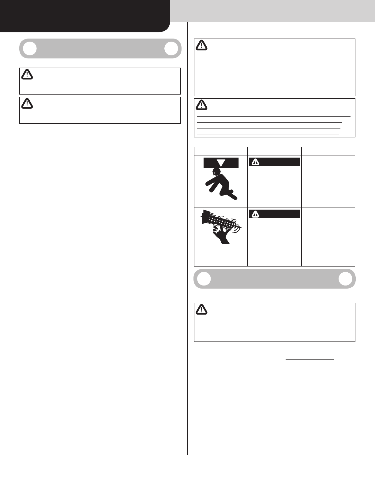
HIGHSPRING TENSION CA NCAUSE
SERIOUSINJURY OR DEAT H.
DONOTadjust, repair or remove springs or parts to
whichsprings are connected, such as steel brack-
ets,cables, wood blocks, fasteners or other parts of
thecounterbalance system.
Adjustmentsor repairs must ONLY be made by a
traineddoor systems technician using proper tools
andinstructions.
DONOTremove, cover or paint over this tag. Prod-
uctuser should inspect this tag periodically for
legibilityand should order a replacement tag from
thedoor manufacturer, as needed.
©Copyright2010Overhead Door Corporation
102081 REV2 06/24/2010
DONOT REMOVE, COVER OR PAINT OVER
THISLABEL. PRODUCT USER SHOULD
INSPECTTHIS LABEL PERIODICALLY FOR
LEGIBILITYAND SHOULD ORDER A
REPLACEMENTFROM THE DOOR
MANUFACTURERAS NEEDED.
346214 NEW 11/19/2010
CALIFORNIAHEALTH AND SAFETY
CODESECTION 25249.6
DRILLING,SAWING, SANDING OR
MACHININGWOOD PRODUCTS GENERATES
WOODDUST, A SUBSTANCE KNOWN TO THE
STATEOF CALIFORNIA TO CAUSE CANCER.
AVOIDINHALING WOOD DUST OR USE A
RESPIRATOR OR OTHER SAFEGUARDS FOR
PERSONALPROTECTION.
WARNING
THISWOOD PRODUCT REQUIRES PROPER
FINISHING PRIORTO ANY DOOR HARDWARE BEING
APPLIED.BOTH INNER AND OUTER FA CESOF THE
SECTION(S),AS WELL AS ALL EDGE SURFACES
MUST BE PREPAREDAND FINISHED IN STRICT
ACC0RDANCETO THE DIRECTIONS GIVEN IN THE
INSTALLATIONINSTRUCTIONS AND OWNER’S
MANUAL UNDER “MAINTENANCE AND PAINTING
INSTRUCTIONS FOR ALLWOOD DOORS”.
IMPROPER STORAGE, IMPROPER TRANSPORTATION
AND/OR DELAYIN FINISHING, THAT ALLOWS FOR
THE EXPOSURE OFTHIS WOOD PRODUCT TO
MOISTUREAND/OR OTHER CONTAMINANTS, VOIDS
THE LIMITED WARRANTY.
IMPORTANT
316986
WARNING
WARNING
Lift handles/gripping points are required
on this door, located as spelled out in the
installation instructions, even if the door
is motor operated.
Failure to install and use these lift handles/
gripping points on this door can result in
serious injury to fingers and/or hands, if
placed in the opening between sections,
when the door is operated manually.
The adjacent bottom corner bracket and
all cable retention features including
milford pins, cotter pins, & clevis pins are
under HIGH SPRING TENSION.
Adjustments and repairs must only be
made by a trained door systems
technician, using proper tools and
instructions.
DO NOT REMOVE, COVER OR PAINT OVER
THIS LABEL.PRODUCT USER SHOULD
INSPECT THIS LABEL PERIODICALLY FOR
LEGIBILITY AND SHOULD ORDER A
REPLACEMENT FROM THE DOOR
MANUFACTURER AS NEEDED.
325304 REV3 06/26/12
©Copyright 2012,
OverheadDoor Corporation
WARNING
WARNING
Lift handles/gripping points are required
on this door,located as spelled out in the
installation instructions, even if the door
is motor operated.
Failure to install and use these lift handles/
gripping points on this door can result in
serious injury to fingers and/or hands, if
placed in the opening between sections,
when the door is operated manually.
The adjacent bottom corner bracket and
all cable retention features including
milford pins, cotter pins, & clevis pins are
under HIGH SPRING TENSION.
Adjustments and repairs must only be
made by a trained door systems
technician, using proper tools and
instructions.
DO NOT REMOVE, COVER OR PAINT OVER
THIS LABEL.PRODUCT USER SHOULD
INSPECT THIS LABEL PERIODICALLYFOR
LEGIBILITY AND SHOULD ORDER A
REPLACEMENT FROM THE DOOR
MANUFACTURER AS NEEDED.
325304 REV3 06/26/12
©Copyright 2012,
OverheadDoor Corporation
SAFETYINSTRUCTIONS
1. Operatedoor ONLY when it is properly
adjustedandfree of obstructions.
2. Ifa door becomes hard to operate,
inoperativeoris damaged, immediately
havenecessaryadjustments and/or repairs
madebya trained door system technician
usingpropertools and instructions.
3. DONOT stand or walk under a moving door,
orpermitanybody to stand or walk under
anelectricallyoperated door.
4. DONOT place fingers or hands into open
sectionjointswhen closing a door. Use lift
handles/grippingpointswhen operating
doormanually.
5. DONOT permit children to operate garage
doorordoor controls.
6. Dueto constant extreme spring tension,
DONOTattempt any adjustment, repair or
alterationtoany part of the door,
especiallytosprings, spring brackets,
bottomcornerbrackets, red colored
fasteners,cablesor supports. To avoid
possiblesevereor fatal injury, have any
suchworkperformed by a trained door
systemtechnicianusing proper tools and
instructions.
7. Onelectrically operated doors, pull down
ropesmustbe removed and locks must be
removedormade inoperative in the open
(unlocked)position.
8. Topsection of door may need to be
reinforcedwhenattaching an electric
opener. Check door and/or opener
manufacturer’s instructions.
9. VISUALLYinspect door and hardware
monthly for worn and/or broken parts.
Check to ensure door operates freely.
10.Te stelectric opener’s safety features
monthly, following opener manufacturer’s
instructions.
11.NEVER hang tools,bicycles, hoses, clothing
or anything else from horizontal tracks.
Track systems are not intended or designed
to support such extra weight.
Placelabel at a readable height on door. DO NOT
remove,cover or paint over this label. Product
usershould inspect this label periodically for
legibilityand should order a replacement label
fromthe door manufacturer as needed.
324100 REV7 09/16/2013
Qualitygarage doors since 1954
WayneDalton
2501S. State Hwy 121 Bus., Suite 200
Lewisville,TX 75067
Forservice, call (800) 827-3667
www.Wayne-Dalton.com
Copyright2013WayneDalton, a
DivisionofOverheadDoor Corp.
Residential warning label, The warning label will
either be on the right or the left end stile.
Bottom section warning labels
Residential Dust label
(For California Residents Only)
Wood label
important notice
Torsion spring tag(s)
(one per spring)
MAINTENANCE
Cleaning Your Garage Door
IMPORTANT: DO NOT USE A PRESSURE WASHER ON YOUR GARAGE DOOR!
An annual inspection of all the surfaces of your garage door(s) will reveal the extent of weath-
ering and the possible need for refinishing. When the finish becomes eroded or thin, clean
and prime any areas showing deterioration. Then completely refinish the door, according to
the directions, listed below, or the manufacturer’s label directions. Proper finishing of the
wood substrates to protect your door(s) from the effects of moisture and sunlight is vital in
extending the service life and beautifying your garage door(s).
The interior and exterior surfaces, as well as all edges must be properly primed, painted and
maintained, to protect and beautify your door. These finishing instructions are intended to
achieve both objectives for your wood doors(s).
NOTE: Be sure to clean behind weatherstrips on both sides and top of door.
CAUTION
NEVER MIX CLEANSERS OR DETERGENTS WITH BLEACH.
GLASS CLEANING INSTRUCTIONS
Clean with a mild detergent solution (same as above) and a soft cloth. After cleaning, rinse
thoroughly.
ACRYLIC CLEANING INSTRUCTIONS
Clean acrylic glazing with nonabrasive soap or detergent and plenty of water. Use your bare
hands to feel and dislodge any caked on particles. A soft, grit-free cloth, sponge or chamois
may be used to wipe the surface. Do not use hard or rough cloths that will scratch the acrylic
glazing. Dry glazing with a clean damp chamois.
NOTE: Do not use any window cleaning fluids, scouring compounds, gritty cloths or solvent-
based cleaners of any kind.
Painting Your Garage Door
Refer to Instruction Insert “Field Painting Wood Door Sections”.
Maintaining The Finish
On Your Garage Door
If the finish is beginning to fade, the door may require a field applied top clear coat. Depend-
ing on environment and usage, this may be necessary after 1 to 3 years of use. Refer to
Instruction Insert “Field Painting Wood Door Sections”.
Operation And Maintenance
OPERATING YOUR GARAGE DOOR: Before you begin, read all warning labels affixed to
the door and the installation instructions and owner’s manual. When correctly installed, your
Wayne Dalton door will operate smoothly. Always operate your door with controlled move-
ments. Do not slam your door or throw your door into the open position, this may cause dam-
age to the door or its components. If your door has an electric opener, refer to the owner’s
manual to disconnect the opener before performing manual door operation below.
10