WE-EF XRX300 LED Series User manual

WE-EF LEUCHTEN
Montage- und
Wartungshinweise für
Sockelleuchten
Serie XRX300 LED
Installation and
Maintenance Instructions for
Beacon Luminaires
XRX300 LED Series

1
Lampen / Lamps
LED 8W / 12W *
* Nominalleistung, aktualisierte Daten siehe www.we-ef.com
* Nominal power, for latest data refer to www.we-ef.com
Schutzart / Protection: IP55, IK10
Schutzklasse / Class I, ta = 25°C
Beacon LuminairesSockelleuchten
ø 180
240
100 ø 180
ø 6
ø 180 ø 270
ø 6
ø 270
360
XRX334XRX324
ø 9 – 14 mm max. 2,5 mm2
Benötigtes Werkzeug
– Schraubendreher mit 3 x 1,0 mm Klinge
– Innensechskantschlüssel 4 mm / 6 mm
Tools required
– Screwdriver with 3 x 1.0 mm blade
– Allan keys 4 mm / 6 mm
400350
Zubehör
Um einen festen Stand der Leuchte zu gewährleisten, sind
die WE-EF Erdstücke ESV4 300-0464 bzw. ESV4 300-0586
zu verwenden.
Installation Accessories
It is recommended to incorporate the optional WE-EF
planted roots ESV4 300-0464 or ESV4 300-0586 to facilitate
a rigid installation.
Erdstück / Planted root
ESV4 ø D1 ø D2 kg
XRX324 300-0464 202 230 6,0
XRX334 300-0586 286 320 7,2
Product Information / Surge Protection
As an option, this luminaire can also be fitted with a surge protector of
Type 2-3 (at the time of order). The technical data can be found directly on the
installed device. If the surge protector has been triggered by an adverse event ,
the luminaire is automatically disconnected from the mains. In that case, the
LED on the surge protector no longer lights up.
For comprehensive protection of the luminaire against lightning and electrical
surges, primary (Type 1) and secondary (Type 2) surge arrestors must be
installed into the power supply. We recommend a combination arrestor
(Type 1+2+3), which is installed in the control cabinet.
The technical planner/installer is responsible for the proper selection, sizing
and installation of the surge protection modules that must be provided on site.
Please note the various protection levels for Class I and II, as well as the
applicable statutory provisions regarding surge protection. Installation and
maintenance may only be performed by a qualified electrician.
Produkthinweis / Überspannungsschutz
Optional kann diese Leuchte (bei der Bestellung) mit einem Überspannungs-
schutz Typ 2-3 ausgestattet werden. Die technischen Daten finden Sie in die-
sem Fall direkt auf dem eingebauten Gerät. Wurde der Überspannungsschutz
im Schadensfall ausgelöst, wird die Leuchte automatisch vom Netz getrennt.
Bei eingeschalteter Stromversorgung leuchtet dann die Leuchtdiode am Über-
spannungsschutz nicht mehr.
Zu einem umfassenden Schutz der Leuchte gegen Blitzeinwirkungen und Über-
spannungen ist es notwendig, zusätzlich einen Grob- (Typ 1) und Mittelschutz-
ableiter (Typ 2) in die Stromversorgung einzubauen. Wir empfehlen einen
Kombiableiter (Typ 1+2+3) für die Montage im Schaltschrank.
Der Fachplaner/Installateur ist für die fachgerechte Auswahl, Dimensionierung
und die Montage der bauseits einzusetzenden Überspannungsschutzbausteine
verantwortlich. Bitte beachten Sie die unterschiedlichen Schutzpegel für die
Schutzklassen I und II sowie die geltenden gesetzlichen Vorschriften zum Über-
spannungsschutz. Die Installation und Wartung ist nur von einem entspre-
chend qualifiziertem Elektro-Fachbetrieb durchzuführen.

2
Installation
The luminaire must be installed and maintained by a suit-
ably qualified person in compliance with latest construc-
tion and electrical regulations and relevant legislation.
Warning: Switch off mains electrical supply prior to
installing and connecting the luminaire. Do not open lumi-
naire while mains supply is switched on.
Notice: If the luminaire is modified by anybody other than
the original manufacturer, then the warranty will no longer
be valid and shall become the full responsibility of the
modifying person/organisation. Claims based on defects
attributable to improper installation and/or application, and
the consequences thereof, are excluded.
In case of component failure due to abnormal circum-
stances or at end of life, replacement must be carried out
by a suitably qualified and trained professional.
In case of questions please contact our technical hotline:
+49 5194 909209 (from Monday - Friday from 08.00 until
16.00 hours.
Installation Procedure
1) Switch off the mains electrical supply.
2) Remove mounting flange A from luminaire head B
by loosening the hexagon socket screws C.
3) Check that rating shown on the luminaire label
conforms with the mains electrical supply.
4) Determine positions for fixing screws D (DIN96-5x30).
Drill relevant holes E and insert heavy duty wall
plugs F.
Caution: Make sure not to damage any electric cable,
water pipe or other devices while drilling holes.
Montage
Montage und Wartung darf nur von geschultem Fachper-
sonal mit entsprechender beruflicher Qualifikation in Über-
einstimmung mit den neuesten elektrischen Installations-
und Sicherheitsvorschriften durchgeführt werden.
Achtung! Vor dem Montieren und Anschließen der
Leuchte die Spannungsversorgung abschalten. Leuchte
niemals bei eingeschalteter Spannungsversorgung öffnen.
Hinweis: Modifikationen an der Leuchte, die nicht durch
den Originalhersteller erfolgen, führen zum Erlöschen der
Garantie und Gewährleistung des Originalherstellers und
zum vollständigen Übergang der Verpflichtungen daraus
auf die modifizierende Person/Organisation. Ansprüche auf-
grund von Mängeln, die direkt oder indirekt auf unsachge-
mäße Montage und/oder Anwendung zurückzuführen sind,
sind ausgeschlossen.
Bei Ausfall von Komponenten aufgrund ungewöhnlicher
Umstände oder am Ende der Lebensdauer darf der
Austausch nur von geschultem Fachpersonal mit entspre-
chender beruflicher Qualifikation ausgeführt werden.
Bei Fragen wenden Sie sich bitte an unsere technische
Hotline unter +49 5194 909209 (Montag - Freitag von
08:00 Uhr bis 16:00 Uhr).
Vorgehensweise
1) Spannungsfreiheit der Anschlussleitung herstellen.
2) Die Innensechskantschrauben Clösen und den Einbau-
flansch Avom Leuchtenkopf Bentfernen.
3) Vergleichen Sie die örtliche Spannung und Frequenz
mit den Daten auf dem Leistungsschild.
4) Legen Sie die Position der Befestigungsschrauben D
(DIN 96-5x30) fest und bohren Sie die Löcher Efür die
notwendigen Dübel F. Beschädigen Sie beim Bohren
keinerlei ggf. in der Wand befindliche elektrische
Leitungen, Wasserrohre o.ä.

3
5) Führen Sie das Kabel G(und falls notwendig das Kabel
Hzur Durchverdrahtung) durch die Kabeleinführung I
und setzen Sie den Einbauflansch Ain Position. Um
den Einbauflansch zu befestigen, durchstechen Sie mit
den Schrauben Ddurch die Nylonstopfen Jund ziehen
Sie die Schrauben an.
Achtung: Um Dichtigkeit zu garantieren, dürfen die
Nylonstopfen Jnicht verrutschen.
6) Gemäß Anschlussplan an die entsprechend markierten
Kontakte der Anschlussklemme Kanschließen.
7) Vergewissern Sie sich, dass alle Oberflächen sauber
und trocken sind, dann den Leuchtenkopf Bwieder
vorsichtig aufsetzen. Ziehen Sie die Innensechskant-
schrauben Cgleichmäßig kreuzweise an. Beachten
Sie den Verdrehschutz (Nocken und Aussparungen).
Wartung
Außer der Reinigung aller äußeren Oberflächen ist keine
spezielle Wartung notwendig. Bitte keine Dampfstrahler zur
Reinigung benutzen.
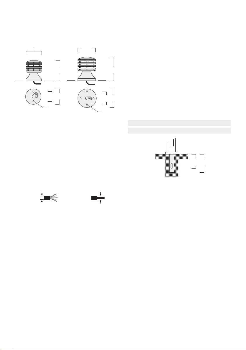
5) Feed mains supply cable G (and the second cable H for
through wiring, if required) through the grommets I,
while setting mounting flange A in position. To fix the
mounting flange, pierce through the nylon plugs J,
insert and tighten screws D.
Important: The nylon plugs J must remain in position
to provide sealing.
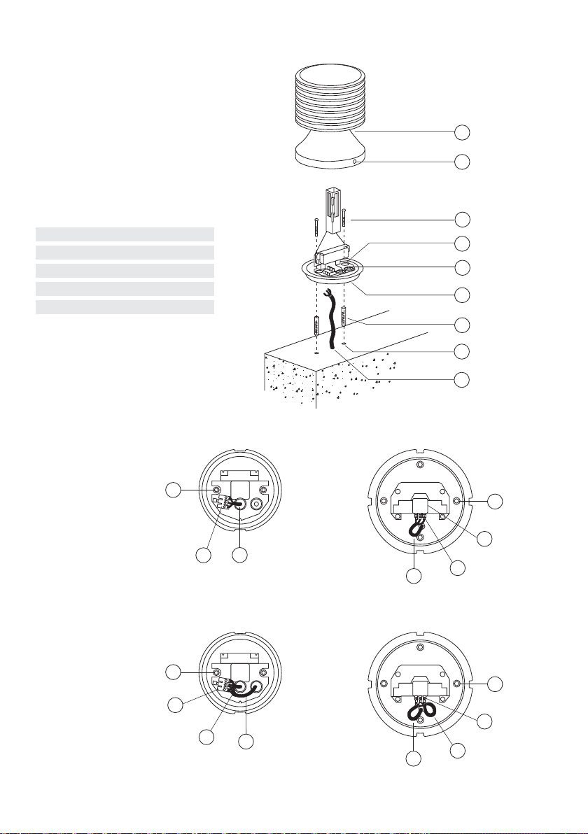
6) Connect the mains supply leads according to wiring
diagram.
7) Ensure that all surfaces are clean and dry. Reposition
luminaire head B careful, while ensuring alignment of
male and female locators. Tighten screws C in a criss-
cross pattern for proper gasket compression.
Pay particular attention to equal tightness.
Maintenance
Apart from cleaning the product's exterior surfaces, no
special maintenance work is required. Do not use high-
pressure cleaners.
Anschlussplan
WE-EF Eco Step Dim® Advanced und
nicht dimmbare Leuchten
SKI Phase an L1, Neutralleiter an N, Schutzleiter an
SKII Phase an L1, Neutralleiter an N
WE-EF Eco Step Dim® Basic
SKI Phase an L1, Steuerphase an L2
Neutralleiter an Nund Schutzleiter an
SKII Phase an L1, Steuerphase an L2, Neutralleiter an N
1-10V / DALI / WE-EF Eco Step Dim® Dynamic
SKI Phase an L1, Neutralleiter an N, Schutzleiter an ,
1-10V, DALI an +und 1-10V, DALI an –
SKII Phase an L1, Neutralleiter an N,
1-10V, DALI an +und 1-10V, DALI an –
Wiring Diagram
WE-EF Eco Step Dim® Advanced and
non dimmable luminaires
Class I Phase to L1, Neutral to Nand Earthing to
Class II Phase to L1, Neutral to N
WE-EF Eco Step Dim® Basic
Class I Phase to L1, Control Phase to L2,
Neutral to Nand Earthing to
Class II Phase to L1, Control Phase to L2, Neutral to N
1-10V / DALI / WE-EF Eco Step Dim® Dynamic
Class I Phase to L1, Neutral to Nand Earthing to ,
1-10V, DALI to +and 1-10V, DALI to –
Class II Phase to L1, Neutral to N,
1-10V, DALI to +and 1-10V, DALI to –

4
I
A
F
E
G
D
C
B
J
XRX324 Einzelanschluss
XRX324 Individual connection
XRX334 Einzelanschluss
XRX334 Individual connection
XRX334 Durchverdrahtun
XRX334 Throu h wirin
XRX324 Durchverdrahtun
XRX324 Throu h wirin
G
J
K
K
M
J
G
G
K
J
H
J
K
GH
Anziehmomente für Schrauben / Torque
Schraube / Screw Anziehmoment / Torque
M4 max. 2,0 Nm
M5 max. 4,0 Nm
M6 max. 6,0 Nm
M8 max. 15,0 Nm
M16 max. 100,0 Nm

XRX300_LED_010117 / 006-1369
Technische Änderungen vorbehalten.
Technical specifications are subject to change.
© WE-EF 2017
WE-EF LIGHTING
Thailand
Tel +66 2 738 9610
Fax +66 2 175 2174
info.asiapacific@we-ef.com
WE-EF LIGHTING
Australia
Tel +61 3 8587 0444
Fax +61 3 8587 0499
info.australia@we-ef.com
WE-EF LIGHTING
United States of America
Tel +1 724 742 0030
Fax +1 724 742 0035
info.usa@we-ef.com
WE-EF LEUCHTEN
Germany
Tel +49 5194 909 0
Fax +49 5194 909 299
info.germany@we-ef.com
WE-EF LUMIERE
France
Tel +33 4 74 99 14 44
Fax +33 4 74 99 14 40
info.france@we-ef.com
WE-EF HELVETICA
Switzerland
Tel +41 22 752 49 94
Fax +41 22 752 49 74
info.switzerland@we-ef.com
WE-EF LIGHTING
United Kingdom
Tel +44 844 880 5346
Fax +44 844 880 5347
info.uk@we-ef.com
www.we-ef.com
Sicherheit
Der Hersteller übernimmt keine Haftung für Schäden, die durch
unsachgemäßen Einsatz oder Montage entstehen.
Werden nachträglich Änderungen an Leuchten und/oder Zubehör
vorgenommen, so gilt derjenige als Hersteller, der diese Änderun-
gen vornimmt.
Safety indices
The manufacturer is then discharged from liability when damage is
caused by improper use or installation.
If any luminaire and/or accessory is subsequently modified, the
persons responsible for the modification shall be considered as
manufacturer.
This manual suits for next models
2
Table of contents