Weatherdock easy2-MOB Operator's manual

easy2-MOB
A22800
MOB: AIS + DSC
Quick Instruction
English
Vers.: 1.0
Stand 1.0

Seite 2Weatherdock AG
www.easyAIS.com
Table of Content
1SAFETY INTRUCTIONS ......................................... 4
2PRODUCT OVERVIEW .......................................... 5
3CONTROLS............................................................ 6
3.1 Alarm flap ............................................................ 6
3.2 Magnet slider ....................................................... 6
3.3 Button "ON" .........................................................7
3.4 Button "TEST".......................................................7
3.5 Antenna................................................................ 8
4OPERATION .......................................................... 9
4.1 TEST function (MOB TEST) .................................10
4.2 ALARM................................................................. 13
4.2.1 Automatic activation.......................................... 13
4.2.2 Manual activation............................................... 15
4.2.3 Functionality ....................................................... 15
4.3 Deactivation (switching off the device) ............19
5PROGRAMMING OF MMSI NUMBERS FOR DSC
DISTRESS CALL USING APP ............................... 20
6INSERTION IN LIFE JACKET ................................. 21
7TECHNICAL DATA ...............................................22
8DECLARATION OF CONFORMITY.......................24
9RESTRICTIONS .....................................................25
10 NOTIZEN ..............................................................26
Revisions
A22800, Stand 1.0, MK –02/2023
Weatherdock AG Seite 3
www.easyAIS.com
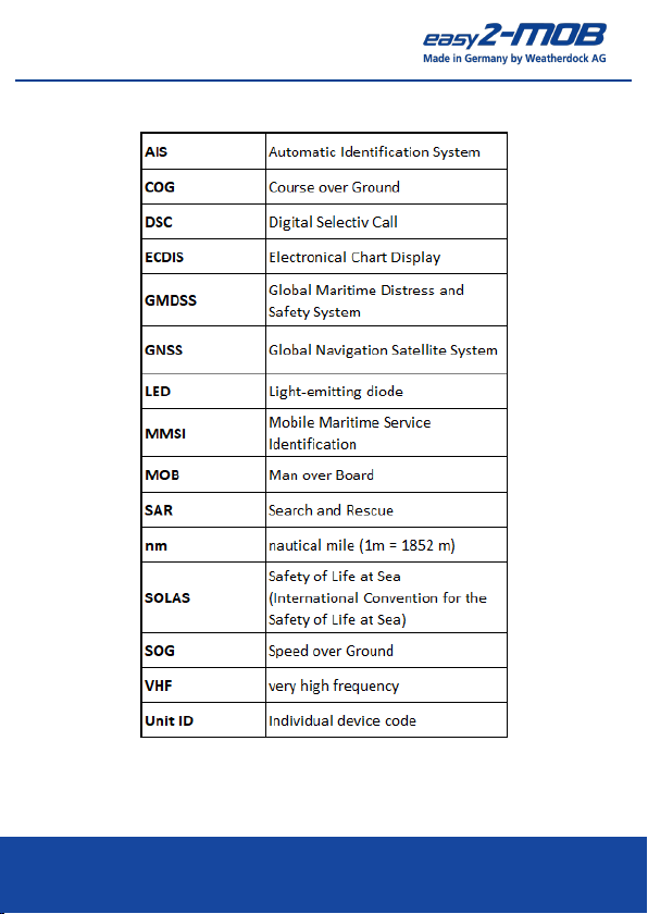
Index of Abbreviations

Seite 4Weatherdock AG
www.easyAIS.com
1Safety Intructions
Read all safety warnings and instructions. Keep all safety no-
tices and instructions for future use!
•Please keep the device out of the reach of children!
•Due to the internal, strong transmitter, medical devices
such as e.g. B. Cardiac pacemakers can be impaired in their
function!
•False triggering of an AIS/DSC emergency call is not a minor
offense and can result in follow-up costs!
•Only have maintenance carried out by authorized service
providers/dealers!
•Unauthorized opening of the device will void the warranty.
Unauthorized and violent opening can destroy the device.
•Caution: There is a risk of explosion if the batteries are re-
placed with an unsuitable type of battery. Dispose of used
batteries according to the instructions.
•If the device is used below 0°C or above 55°C, the capacity
of the batteries will decrease. Keep the device away from
heat or hot environments. The batteries inside the easy2-
MOB could overheat, possibly even explode or burn and
cause damage to the device and the environment!
Weatherdock AG Seite 5
www.easyAIS.com
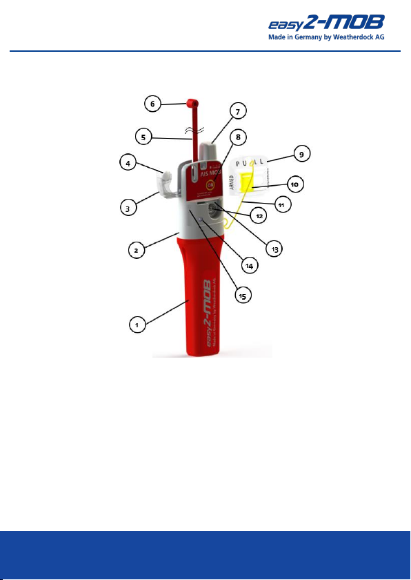
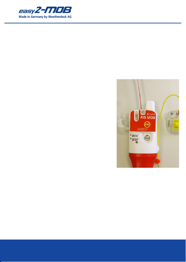
2Product Overview
1. Base housing
2. Upper housing
3. Antenna flap
4. Water-soluble
cellulose tablet
5. Antenna
6. Antenna head
7. GPS antenna
8. Button „ON“
9. Alarm flap
10. Magnet slider
11. Lanyard, 1 m
12. Button „TEST“
13. Program-LED
14. Status-LED
15. Emergency light LED
Seite 6Weatherdock AG
www.easyAIS.com
3Controls
3.1 Alarm flap
The transparent alarm flap (9) in the
upper area of the device serves to
avoid false alarms and at the same
time secures the antenna flap (3).
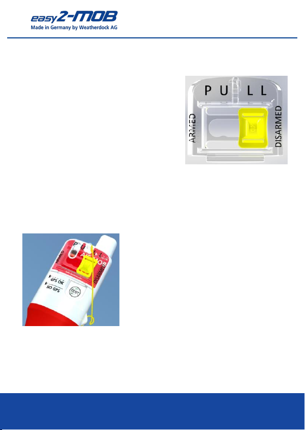
3.2 Magnet slider
New regulations stipulate that automatic activation can be
switched off for an AIS-DSC-MOB device. This is done by the
magnetic slide (10) integrated in the alarm flap.
•"Disarmed" means that the auto-
matic is switched off
•"Armed" means that the automatic
is activated
Weatherdock AG Seite 7
www.easyAIS.com
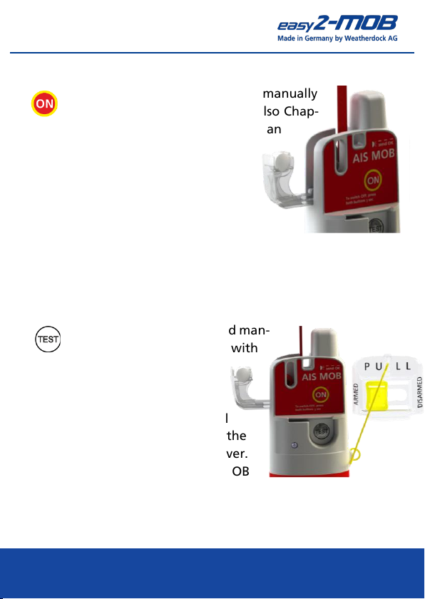
3.3 Button "ON"
The device can be activated manually
with the "ON" button (8) (see also Chap-
ter 4.2.2). Pressing this button triggers an
AIS distress signal, which is received
by all ships and coast radio stations
in the area equipped with an AIS re-
ceiver.
A DSC alarm is sent parallel to the AIS signal.
(see also Chapter 4.2.3)
3.4 Button "TEST"
The device can be activated man-
ually for a function test with
the "TEST" button (12).
By pressing this button, an AIS
test distress signal is triggered
once, which is received by all
ships and coast radio stations in the
area equipped with an AIS receiver.
The additional text message "MOB
TEST" informs each recipient of this test signal that it is a
function test, i.e. not an emergency.
Seite 8Weatherdock AG
www.easyAIS.com
In addition to the AIS telegrams, a DSC telegram is sent to
the programmed MMSI numbers. (See Chapter 5 for more in-
formation on programming the MMSI numbers).
The red LEDs flash for the period of the test transmissions.
(For more information on the TEST function, see Chapter 4.1)
3.5 Antenna
When rolled up, the antenna (5) is lo-
cated in the upper part of the trans-
mitter. It is secured with a water-sol-
uble tablet (4), the antenna- and
alarm flap. After the antenna flap (3)
has been triggered by contact with
water or the alarm flap (9) has been
removed by hand, the antenna un-
rolls itself upwards. The device acti-
vates automatically when it comes
into contact with water, without you
having to intervene (the magnetic slider (10) must be set to
"armed").
Weatherdock AG Seite 9
www.easyAIS.com
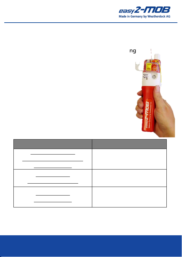
4Operation
The AIS MOB easy2-MOB can float without additional aids.
In heavy seas, the easy2-MOB may need a long
time to determine a GPS/GNSS position while
swimming.
For best AIS transmission performance and
GPS/GNSS reception accuracy, hold the beacon
in your hand as high out of the water as pos-
sible.
Table 1: Flashing/Lighting Pattern Operating Status
LED display
Operating condition
FLASH LED (13/14) +
Emergency lights LEDs (15)
flashes regularly
Device sends
Status-LED (14)
lights up permanently
Position is determined
Status-LED (14)
flashes regularly
Position reception is flawless.
A position is continuously
determined

Seite 10 Weatherdock AG
www.easyAIS.com
4.1 TEST function (MOB TEST)
Test the easy2-MOB for the send function at regular intervals.
A six-monthly test is usually sufficient. Testing too often will
reduce battery capacity. The battery is designed for 5 years
and up to 30 test activations (see also table "Technical
Data",Chapter 7).
The antenna mechanism does not have to be triggered
for the function test!
Carrying out the test function:
•Before you start the test, you must set the magnetic slide
(10) to the "Armed" position and a "Mothership" MMSI
should already be programmed (see Chapter 5).
•Have the DSC radio and AIS chartplotter ready for opera-
tion.
•Leave the antenna rolled up in the device.
•Press the "TEST" button (12) for 1 second until the yellow
LED (14) lights up. Make sure you have a clear view of the
sky for good GPS/GNSS reception conditions.
This manual suits for next models
2
Table of contents
Other Weatherdock Marine Equipment manuals


