Incite Fire BExDS120D User manual
__________________________________________________________________________________________________________________________________
EuropeanSafetySystemsLtd. Impress House, MansellRoad, Acton, LondonW37QHsales@e-2-s.com Tel: +44(0)208 743 8880
www.e-2-s.com Fax: +44(0)208 7404200
DocumentNo. IS2451-PIssueE19-02-10Sheet1of 4(1)
INSTRUCTION MANUAL(ATEX/IECEx)
BExDS120DandBExDS110D
FlameproofSounders
ForuseinFlammableGasandDustAtmospheres
1)Introduction
The BExDS120DandBExDS110Dareflameproof sounders
whicharecertified tomeettherequirements of theATEX
directive94/9/ECandthe IECEx scheme.The sounders
produceloudwarningsignals and canbe usedin hazardous
areaswhere potentially flammable gasand dust atmospheres
maybepresent.Thirty-twodifferent firststagealarmsounds
canbeselected byinternal switches,and each onecan be
externally changed toasecondorthirdstage alarmsound
(seetone tableonPage4). TheBExDS120Dunitproduces
output levelsin the117dB(A)rangeandtheBExDS110Dunit
producesoutputlevelsinthe 110dB(A) range.Bothsounders
canbe usedin Zone 1 and Zone 2areas with gasesin groups
IIA, IIB and IIC and temperatureClassifications of T1,T2,T3
and T4. Forambienttemperaturesover +55ºCthe gas groups
are limited to IIAand IIB. Theycan also beusedinZone 21
and Zone22 areasfor combustible dustsandhavean IP rating
of IP 67andasurface temperatureratingofT100ºCupto
+55ºCandT115ºCover +55ºC.
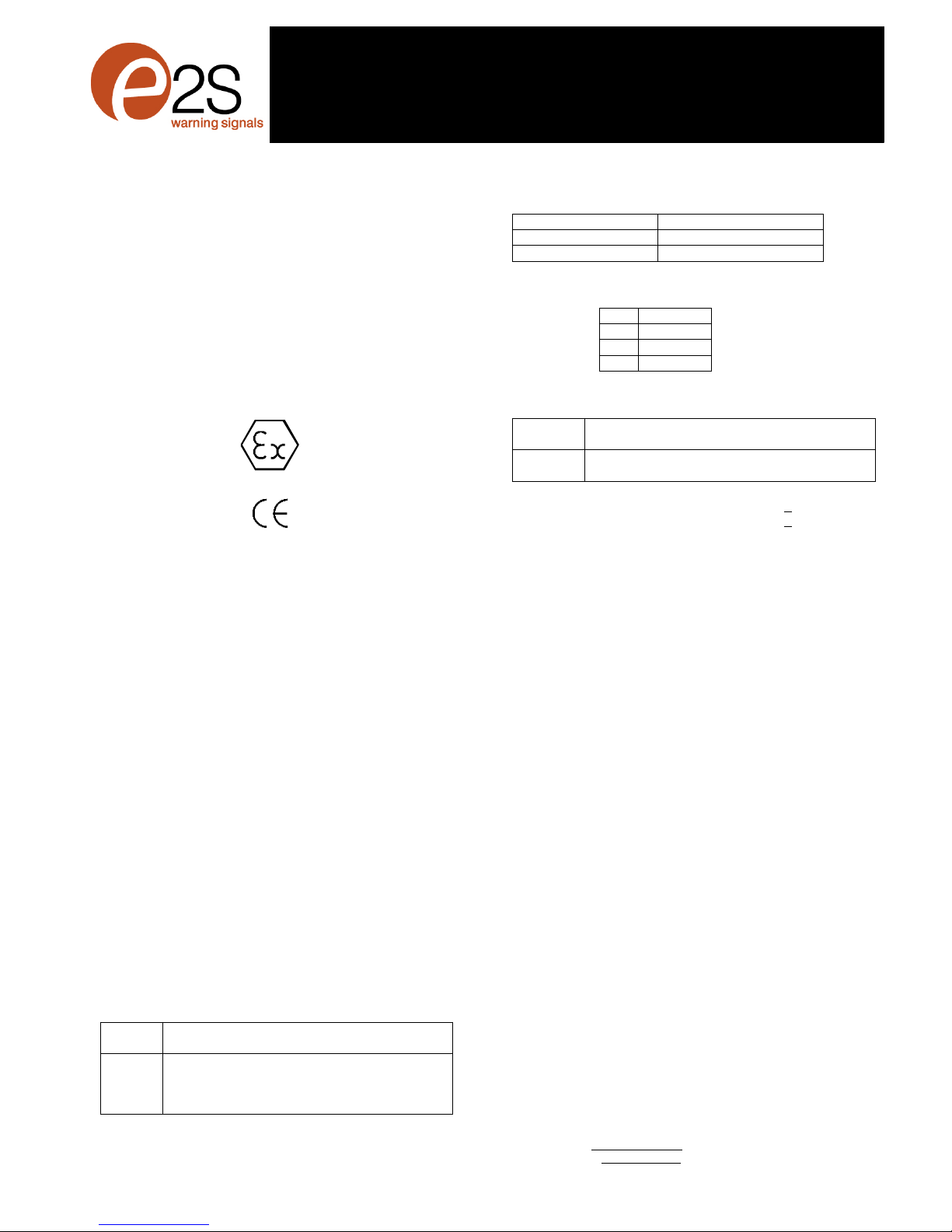
2)Marking
All unitshavearating label, whichcarriesthe following
important information:-
Input Voltage: DC Units 12Vor 24Vor 48V
AC Units 230V or 110Vor 115V
Codes:ExdIICT4 for Ta –50°Cto+55ºC
ExdIIBT4 for Ta –50°Cto+70ºC
ExtDA21IP67T115°Cbasedonmax Ta of+70°C
CertificateNo’s KEMA99ATEX6312
IECExKEM10.0003
“Warnings” DONOTOPENWHENANEXPLOSIVE
GAS ORDUSTATMOSPHEREISPRESENT
COVERBOLTSCLASS A4-80
USE HEATRESISTINGCABLES ANDCABLEGLANDS
(Rated 110ºC)ATAMB. TEMPERATURES OVER40ºC
Year of Construction/
Serial No. i.e. 10 / 1DS22000001
3) TypeApprovalStandards
The soundershaveECType ExaminationandIECEx
certificates issuedby KEMAandhave beenapproved tothe
followingstandards:-
EN60079-0:2006 IEC60079-0:2004(Ed4) GeneralRequirements
EN60079-1:2007 IEC60079-1:2007 (Ed6) Flameproof Enclosure‘d’
EN61241-0:2006 IEC61241-0:2004(Ed1)DustGeneral
Requirements
EN61241-1:2004 IEC60079-1:2004(Ed1)DustEnclosurestD
4) Installation Requirements
The soundersmustbeinstalled inaccordancewiththelatest
issues oftherelevantpartsof the EN60079 standardsorthe
equivalent IECstandards –Selection,Installationand
maintenanceof electrical apparatusforuse in potentially
explosiveatmospheres(other thanminingapplicationsor
explosiveprocessing and manufacture):-
EN60079-14:2008 ElectricalInstallationsinHazardous
IEC60079-14:2007(Ed4) Areas(otherthan mines)
EN60079-10:2003 Classificationof HazardousAreas
IEC60079-10:2008(Ed1)
The installationof theunitsmustalsobein accordancewith
anylocal codesthat may apply and should onlybe carried out
byacompetentelectricalengineerwhohasthenecessary
training.
5) Zones, GasGroup, Category,IPRating and
TemperatureClassification
The BExDS120DandBExDS110Dsoundershavebeen
certified Ex de IIC T4 for Ta–50°Cto +55ºCand Exde IIB T4
forTa–50°Cto +70ºCfor gasandEx tD A21IP67T115ºC
basedon max. Ta of +70ºC for dust. Thismeans thatthe units
canbe installed in locationswith thefollowingconditions:-
AreaClassification Gas:
Zone 1
Explosivegasair mixturelikely tooccurin
normal operation.
Zone 2
Explosivegasair mixturenot likely to occur,
andifitdoes, it willonly existfor ashort time.
GasGroupings:
GroupIIA
Propane
GroupII
B
Ethylene
GroupIIC
(Up to
+55ºC
only)
Hydrogen andAcetylene
TemperatureClassification:
T1
400
o
C
T2
300
o
C
T3
200
o
C
T4
135
o
C
0518
II 2G/D
Epsilonx:
Equipment Groupand
Category:
CE Marking:
NotifiedBody No.

__________________________________________________________________________________________________________________________________
EuropeanSafetySystemsLtd. Impress House, MansellRoad, Acton, LondonW37QHsales@e-2-s.com Tel: +44(0)208 743 8880
www.e-2-s.com Fax: +44(0)208 740 4200
DocumentNo. IS2451-PIssueE19-02-10Sheet2of 4(2)
AreaClassification Dust:
Zone 21
Explosive dust airmixturelikely to occur in
normal operation.
Zone 22
Explo
sive dust air mixturenotlikelytooccur,
andif it does, it will onlyexist fora short time.
IPRating: IP67 T100ºC Ta< +55ºC
T115ºC Ta< +70ºC
EquipmentCategory: 2G/D
Ambient Temperature Range:
-50°C to+55°CGasGroupsIIA, IIB andIIC
-50°C to+70°CGasGroup IIAandIIB
6) SounderLocationand Mounting
The locationof the soundersshould bemadewith due regard
tothearea overwhich the warning signal must beaudible. The
soundersshould onlybefixedto services thatcan carrythe
weight ofthe unit.
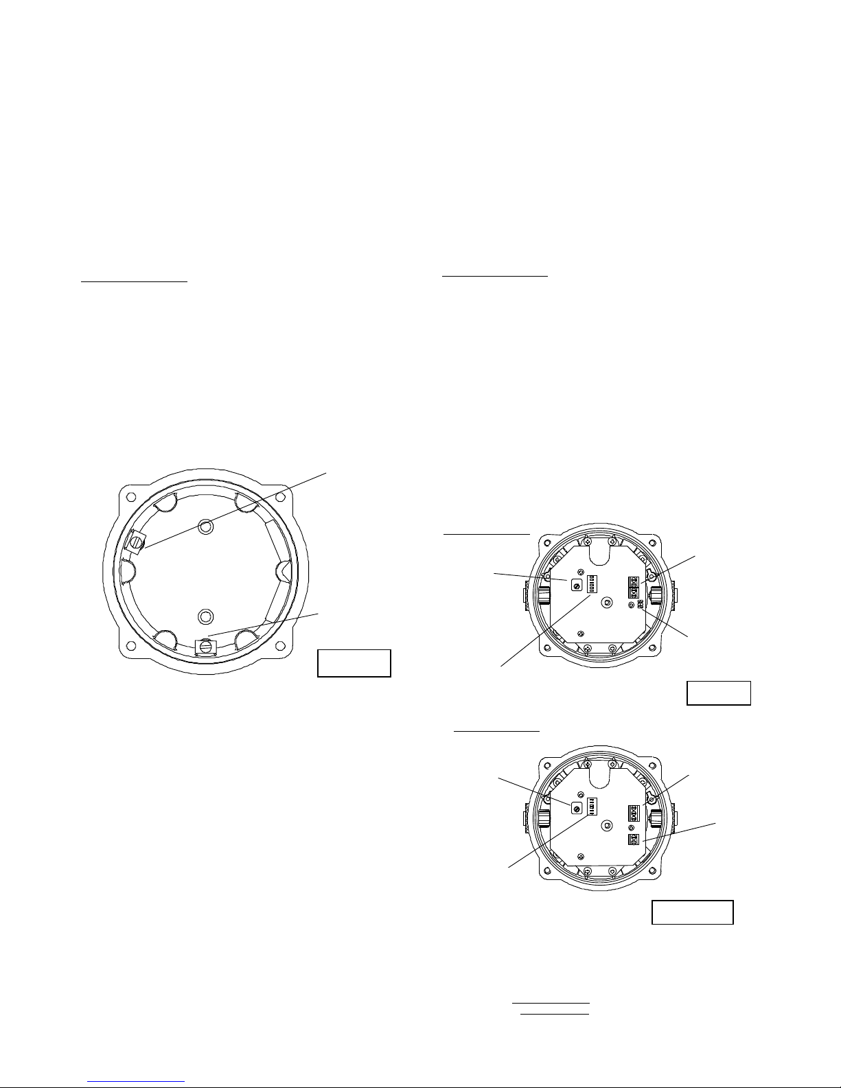
The sounder should besecurely boltedto asuitablesurface
usingthe7mmdiameter boltholesinthe stainlesssteelU
shapedmounting bracket(see figure1). The anglecan then be
adjusted in the directionthat the sound is primarily required to
cover. Thiscan beachieved by looseningthetwolarge bracket
screwsin the side of theunit, which allow adjustment insteps
of18°.Oncompletion of the installation thetwo largebracket
adjustment screws onthe sideof theunit must befully
tightenedto ensurethat theunit cannotmovein service.
7) Access totheFlameproofEnclosure
Inorder to connectthe electrical supplycables to the sounder
it is necessary to removetheflameproofcovertogain access
totheflameproofchamber. To achievethisremovethefour M6
hexagon sockethead screws (see figure2) andwithdrawthe
flameproof cover takingextremecarenotto damagethe
flameproof joints in theprocess.
Notethefour M6screwsareClassA4-80stainlesssteel
and onlyscrewsof thiscategorycanbeused on these
sounders. It is therefore importantthatthese screws and their
springwashersarekept ina safe place duringinstallation.
Oncompletionof thecable wiring installationtheflameproof
jointsshould be inspectedto ensurethat theyarecleanand
thatthey havenotbeen damagedduringinstallation.Also
checkthat theearthbonding wirebetween thetwocasting
sectionsissecureandthe ‘O’ringseal isin place.
Whenreplacing theflameproofcover castingensurethatit is
squarewiththeflameproof chambercastingbeforeinserting.
Carefully pushthecover in place allowing timeforthe airtobe
expelled.Only afterthecoverisfully inplace shouldthe four
M6 StainlessSteelA4-80 coverbolts and their springwasher
be inserted and tighteneddown. Ifthe coverjams whileit is
beinginserted, carefully removeit andtryagain.Never usethe
cover boltstoforcethecover intoposition.
8) PowerSupplySelection
Itis important that asuitable powersupplyisused torunthe
sounders.Thepowersupply selected musthave the
necessary capacity toprovidethe input currentto all ofthe
soundersconnected tothesystem.
The followingtableshowstheinputcurrent taken by the
various sounderunits:-
UnitType InputInput Max.
VoltageCurrentI/PVolts
BExDS120D 24VDC 800mA 30V
BExDS120D 12VDC 850mA 15V
BExDS120D 48VDC 420mA 58V
BExDS120D 230VAC90mA 264V
BExDS120D 110VAC200mA 121V
BExDS120D 115VAC180mA 126V
BExDS110D 24VDC 265mA 30V
BExDS110D 12VDC 195mA 15V
BExDS110D 48VDC 130mA 58V
BExDS110D 230VAC56mA 264V
BExDS110D 110VAC93mA 121V
BExDS110D 115VAC110mA 126V
The input currentwillvaryaccordingtothe voltageinputlevel
and the frequencyofthetoneselected.The current levels
shown abovearefor the 440Hz Continuoustone@nominal
input voltage.The24V and48V DC units and the230V AC,
115VAC and110VACunitshaveaswitchingvoltage
regulator circuitand thereforetheinputcurrent level will
decreaseslightlyas the inputvoltagein increasedandwill
increaseslightly as the input voltage isreduced.The 12V units
do nothaveavoltage regulator andthereforetheir input
current will increase whentheinputvoltage isincreased.
Figure 1
PlasticAcousticHorn
(Anti-staticPlastic)
Flameproof
Chamber
Flameproof
Cover
S/SMounting
Bracket
Figure2
4off M6CoverScrews
ExternalEarth
Terminal
__________________________________________________________________________________________________________________________________
EuropeanSafetySystemsLtd. Impress House, MansellRoad, Acton, LondonW37QHsales@e-2-s.com Tel: +44(0)208 743 8880
www.e-2-s.com Fax: +44(0)208 740 4200
DocumentNo. IS2451-PIssueE19-02-10Sheet3of 4(3)
The abovetable also showsthemaximum voltagesat which
the sounderscanbe operated.
9) CableSelection
Whenselecting the cable size consideration mustbegivento
the inputcurrentthat each unitdraws (seetableabove), the
numberofsounders onthelineandthelengthof thecable
runs.Thecablesizeselectedmust havethenecessary
capacitytoprovide theinputcurrent toall ofthe sounders
connected to the line.
SAFETY WARNING: IfthehighoutputBExDS120Dsounders
are usedathighambienttemperatures,i.e. over+40ºC, then
the cable entry temperaturemay exceed+70ºCand therefore
suitable heat resistingcablesmustbeused, witharated
service temperatureofat least 110ºC.
10) Earthing
Both ACandDC sounder unitsmustbeconnectedtoagood
qualityearth. The units are provided with internal and external
earthing terminalswhichare both locatedon theterminal
chamber sectionoftheunit (seefigures 2and3).
Whenusingtheinternal earth terminalensure thatthe
stainlesssteelM4flat washer isbetweentheincoming earth
wireand the enclosure.
When using theexternal earthterminal a cablecrimp lugmust
be used. Thecablelugshould be locatedbetween thetwoM5
stainlesssteelflat washers. TheM5stainlesssteel spring
washermust be fixed betweenthe outer flatwasher andthe
M5 stainless steel nut toensurethatthe cablelugissecured
againstlooseningand twisting.
The internalearthbondingwireensures that agoodquality
earth is maintained betweentheflameproofchambercasting
and the flameproofcovercasting.
11) CableGlands
The BExDS120DandBExDS110D soundershave dual cable
glandentries whichhaveanM20 x1.5entry threadas
standard.Onlycable glands approvedforEx‘d’applications
canbe used, which mustbe suitablefor the type of cable being
usedandalsomeetthe requirementsoftheEx‘d’ flameproof
installation standardEN60079-14:2008 / IEC60079-14:2007.
Whenonly onecable entry isusedtheotheronemustbe
closed with an Ex ‘d’flameproofblankingplug,which mustbe
suitablyapprovedfortheinstallation requirements.
For combustibledust applications, the cable entry deviceand
blanking elementsshall be in type ofexplosionprotection
increasedsafety"e"or flameproof enclosure "d"andshall have
an IP 6Xratingaccording toEN60529:1992.
SAFETY WARNING: IfthehighoutputBExDS120D sounders
are usedathighambienttemperatures,i.e. over+40ºC, then
the cable entry temperaturemay exceed+70ºCand therefore
suitable heatresisting cable glands must beused,with arated
servicetemperatureofat least110ºC.
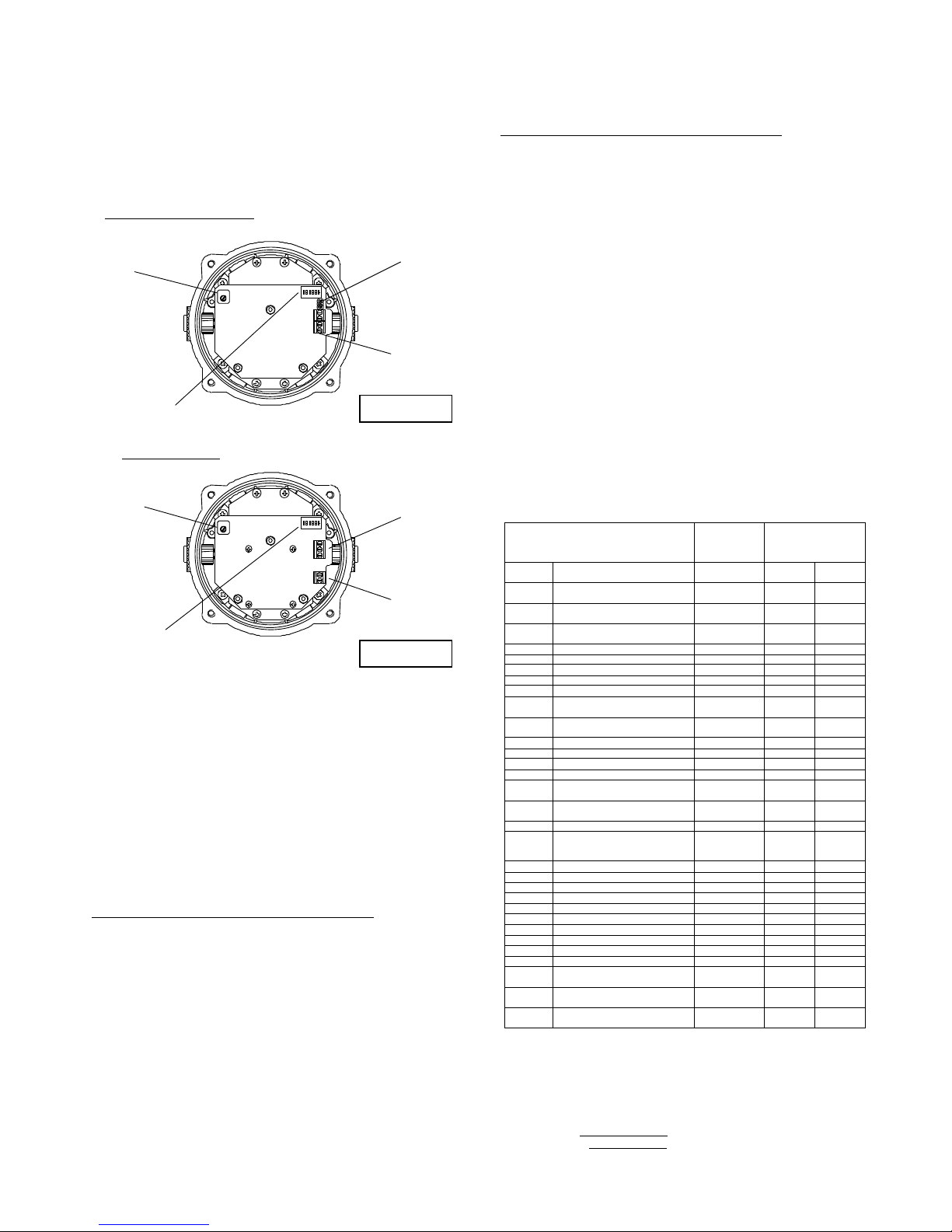
12) CableConnections
The cableconnectionsaremadeinto theterminal blockson
the electronicpcbassembly located in theflameproof
enclosure.Seesection7ofthis manual foraccesstothe
flameproofenclosure. On theAC unitsatwo-wayterminal
blockis providedforthe liveand neutral mainssupply wires
and athreewayterminal blockisprovided forlinkingthe
secondand thirdstages, (seefigures 5and7). On theDC
unitsafourwayterminalblockis providedfor +ve and–ve
supply inputand second and third stagemodesofoperation,
(seefigures 4and6).
A singlewire withacross sectionalarea ofup to 4mm²can be
connectedto eachterminal way or ifaninput andoutputwire
isrequired two 2.5mm²wires can be connectedtoeach
terminalway.Whenconnectingwirestotheterminalsgreat
2off M20
CableEntries
InternalEarthTerminal
Figure3
InternalBonding
WireTerminal
Figure 4
Figure5
BEx
D
S120D DC
Sounder
BEx
D
S120DAC
Sounder
VolumeControl
DIPSwitch
DCTerminals
StageHeaders
VolumeControl
DIPSwitch
Stage Terminals
ACTerminals
C
S3
S2
N
L
+
-
S3
S2
__________________________________________________________________________________________________________________________________
EuropeanSafetySystemsLtd. Impress House, MansellRoad, Acton, LondonW37QHsales@e-2-s.com Tel: +44(0)208 743 8880
www.e-2-s.com Fax: +44(0)208 740 4200
DocumentNo. IS2451-PIssueE19-02-10Sheet4of 4(4)
care should be takento dress thewire so that whenthecover
isinsertedintothechamberthe wiresdo not exert excess
pressureonthe terminal blocks.Thisis particularlyimportant
whenusing cableswith largecrosssectional areassuchas
2.5mm²and above.
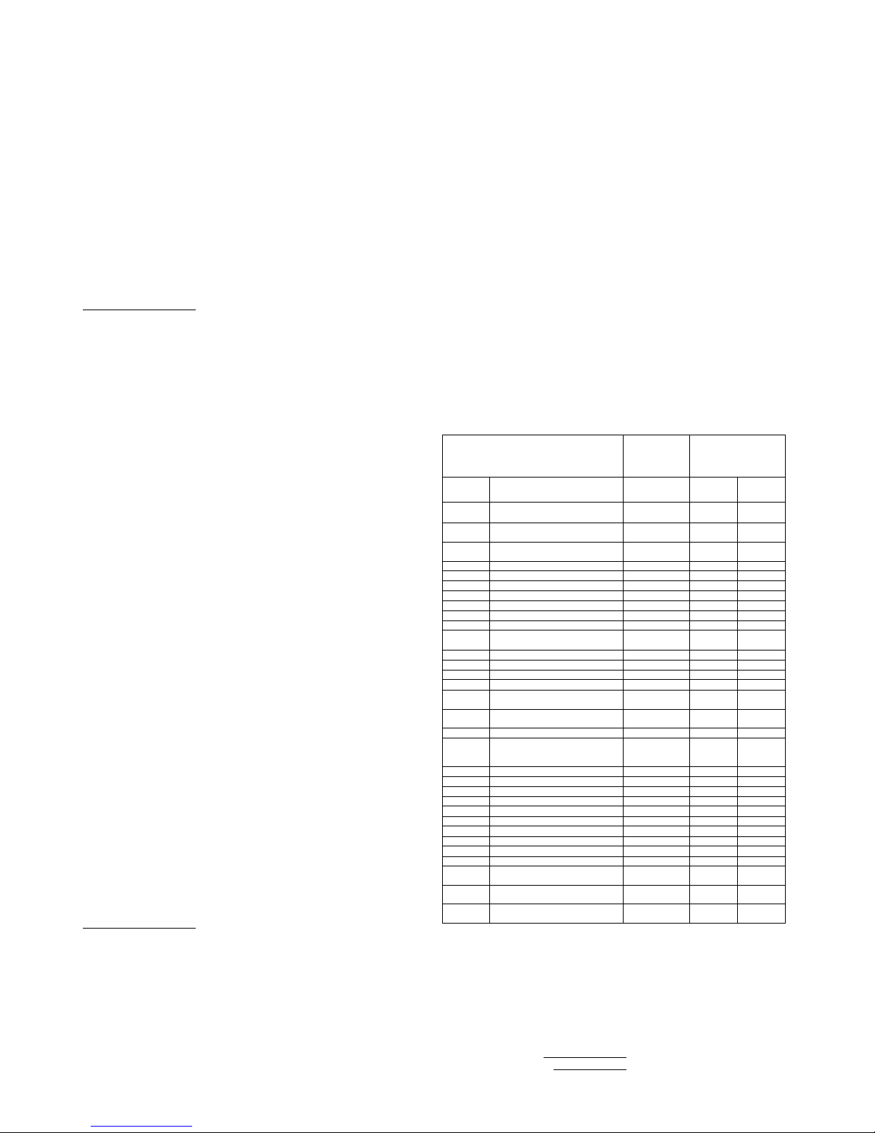
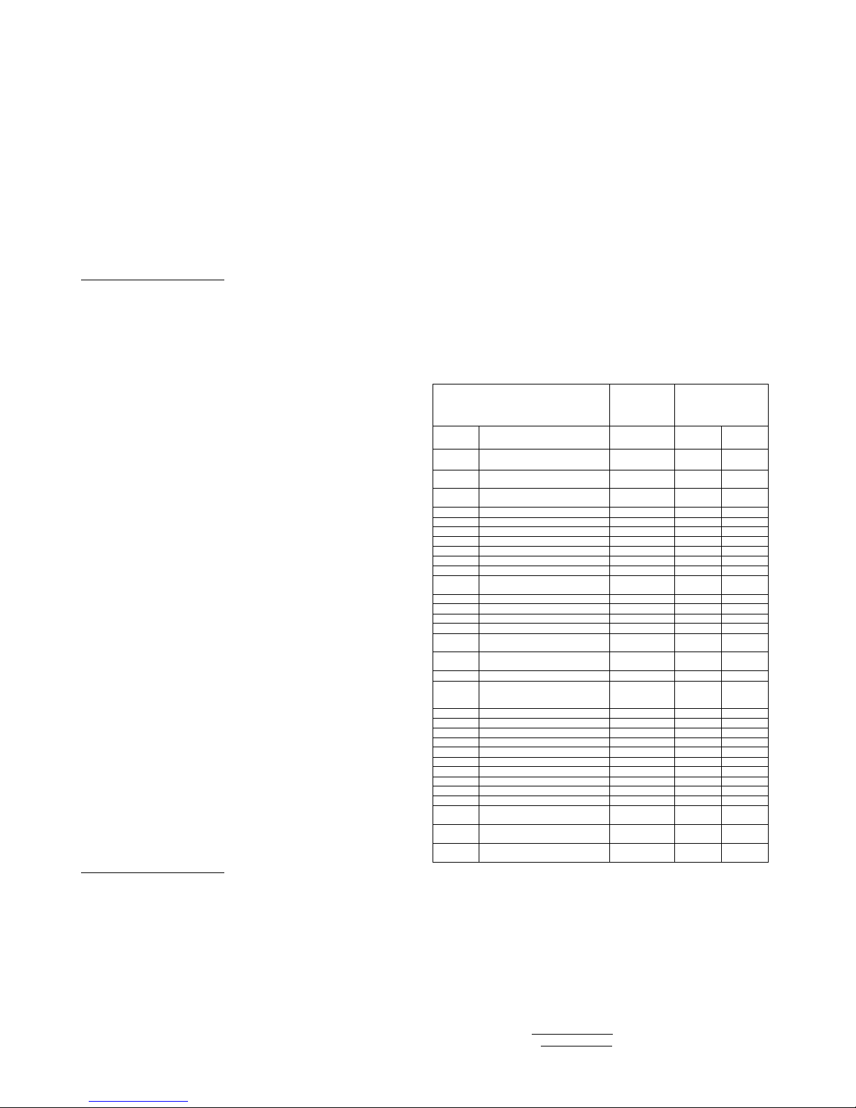
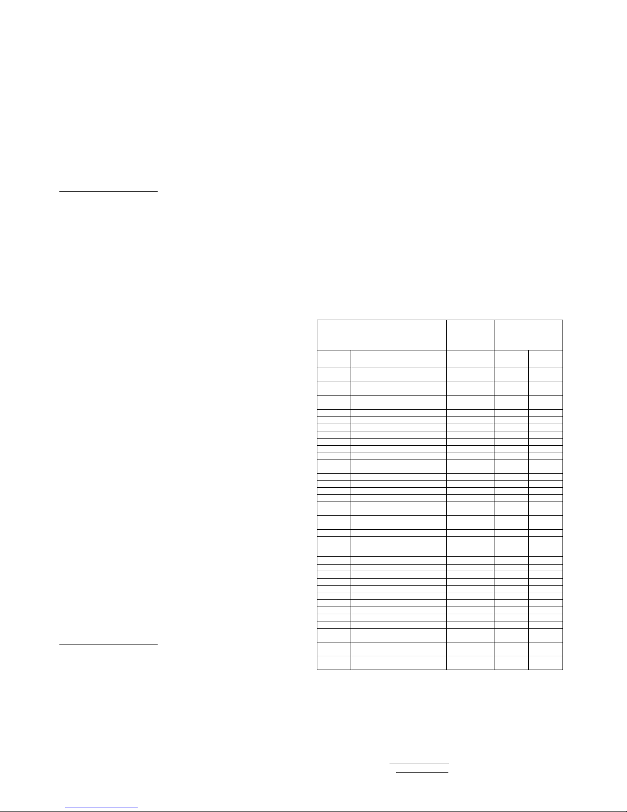
13) ToneSelection and2ndand3rdStageAlarms
The BExDS120Dand BExDS110D sounders have 32different
tones that can beselectedforthefirststagealarm. The
sounderscan thenbe switchedtosound second and third
stage alarm tones.Thetones are selected byoperationofa
DIP switchonthepcbforboth DCandACunits.The tone
table onpagefour shows theswitch positions for the 32tones
and whichtonesareavailable for the second and third stages.
Tooperatethesounderonstageonesimplyconnect the
supply voltage tothe normal supply terminals (+ve and –vefor
DC units, LandNforAC units).
The operation of thesecondandthirdstagesisdifferent for DC
and AC units.
DC UnitsSecond and ThirdStage Tone Selection
The BExDS120DandBExDS110D DCsounders havethe
facility to use either+ve or –veswitching to change the toneto
the secondandthirdstages.For –veswitchingconnect thetwo
headersonthe pcbto theleft-hand(marked –ve)and centre
pins.For +ve switchingconnecttheheadersto the righthand
(marked+ve) andthecentre pins. Tochange tothesecond
stage tone, connecteither a-ve or +ve supply line toterminal
S2, dependingon whichswitching mode isbeingused while
maintainingthedc supply tothe+veand–veterminals.
Similarlyforthe third stagetone, connecta-ve or+vesupply
line toterminalS3. Thesupplyto the S3 terminalwill
automaticallyoverride a supply totheS2terminal.
AC UnitsSecond and ThirdStageTone Selection
To select the second and third stagetones on theBExDS120D
and BExDS110D ACsounderstheCommon(C)terminalon
the three wayterminalblockon the pcb isconnectedto theS2
terminalfor the secondstage tone and theS3 terminal for the
thirdstage tone.
14) VolumeControl
All BExDS120D andBExDS110Dsounders, withthe exception
of 12VDC units, haveavolume controltoadjusttheoutput
level. Toset the requiredoutput level, adjust the potentiometer
onthe pcb. For maximumoutput levelthepotentiometer
shouldbeset tothefully clockwiseposition.
15) EndofLineMonitoring(DCUnits)
OnBExDS120D and BExDS110D DCunits,dcreverseline
monitoringcan beused ifrequired.All DCsoundershavea
blocking diode fitted in their supplyinput lines.Anendofline
monitoringdiode oran end oflinemonitoringresistorcan be
connectedacross the +ve and –ve terminals.If an end of line
resistorisused it musthave aminimumresistancevalueof
3k3 ohmsandaminimum wattageof 0.5watts oraminimum
resistancevalue of 500ohmsanda min.wattage of 2 watts.
TONESELECTIONTABLENoteSwitchNo.6isnotused
ToneSelection
DIPSwitch
Settings
StageSelection
Stage1
FrequencyDescription
12345
Stage2
Stage3
1
Continuous1000Hz
Toxicgasalarm
00000
Tone31
Tone11
2
Alternating800/1000Hzat0.25s
intervals
10000
Tone17
Tone5
3
SlowWhoop 500/1200Hzat0.3Hz
with0.5sgaprepeated
01000
Tone2
Tone5
4
Sweeping 800/1000 at1Hz
11000
Tone6
Tone5
5
Continuousat2400Hz
00100
Tone3
Tone27
6
Sweeping 2400/2900Hzat7Hz
10100
Tone7
Tone5
7
Sweeping 2400/2
900Hzat1Hz
01100
Tone10
Tone5
8
Siren500/1200/500Hzat0.3Hz
11100
Tone2
Tone5
9
Sawtooth1200/500Hzat1Hz
00010
Tone15
Tone2
10
Alternating2400/2900Hzat2Hz
10010
Tone7
Tone5
11
Intermi
ttent1000Hzat0.5Hz
Generalalarm
01010
Tone31
Tone1
12
Alternating800/1000Hzat0.875Hz
11010
Tone4
Tone5
13
Intermittent2400Hzat1Hz
00110
Tone15
Tone5
14
Intermittent800Hz0.25son 1soff
101
10
Tone4
Tone5
15
Continuousat800Hz
01110
Tone2
Tone5
16
Intermittent660Hz150mSon,
150mSoff
11110
Tone18
Tone5
17
Alternating544Hz
(100mS)/440Hz(400mS)
00001
Tone2
Tone27
18
Intermittent660Hz
1.8son, 1.8soff
10001
Tone2
Tone5
19
1400Hzto1600Hzsweepupover
1s-1600Hzto1400Hzsweepdown
over0.5s
01001
Tone2
Tone5
20
Continuous660Hz
11001
Tone2
Tone5
21
Alternating554/440Hzat1Hz
0
0101
Tone2
Tone5
22
Intermittent554Hzat0.875Hz
10101
Tone2
Tone5
23
800Hzpulsingat2Hz
01101
Tone6
Tone5
24
Sweeping 800/1000Hzat50Hz
11101
Tone29
Tone5
25
Sweeping 2400/2900Hzat50Hz
0
0011
Tone29
Tone5
26
Simulatedbell sound
10011
Tone2
Tone1
27
Continuous554Hz
01011
Tone26
Tone5
28
Continuous440Hz
11011
Tone2
Tone5
29
Sweeping 800/1000Hzat7Hz
00111
Tone7
T
one5
30
420Hzrepeating0.625son, 0.625s
offAustralianalertsignal
10111
Tone32
Tone5
31
1200/500Hzat1Hz
Preparetoabandonplatform
01111
Tone11
Tone1
32
Sweeping 500/1200Hz3.75son,
0.25soff 15Hz
1111
1
Tone26
Tone1
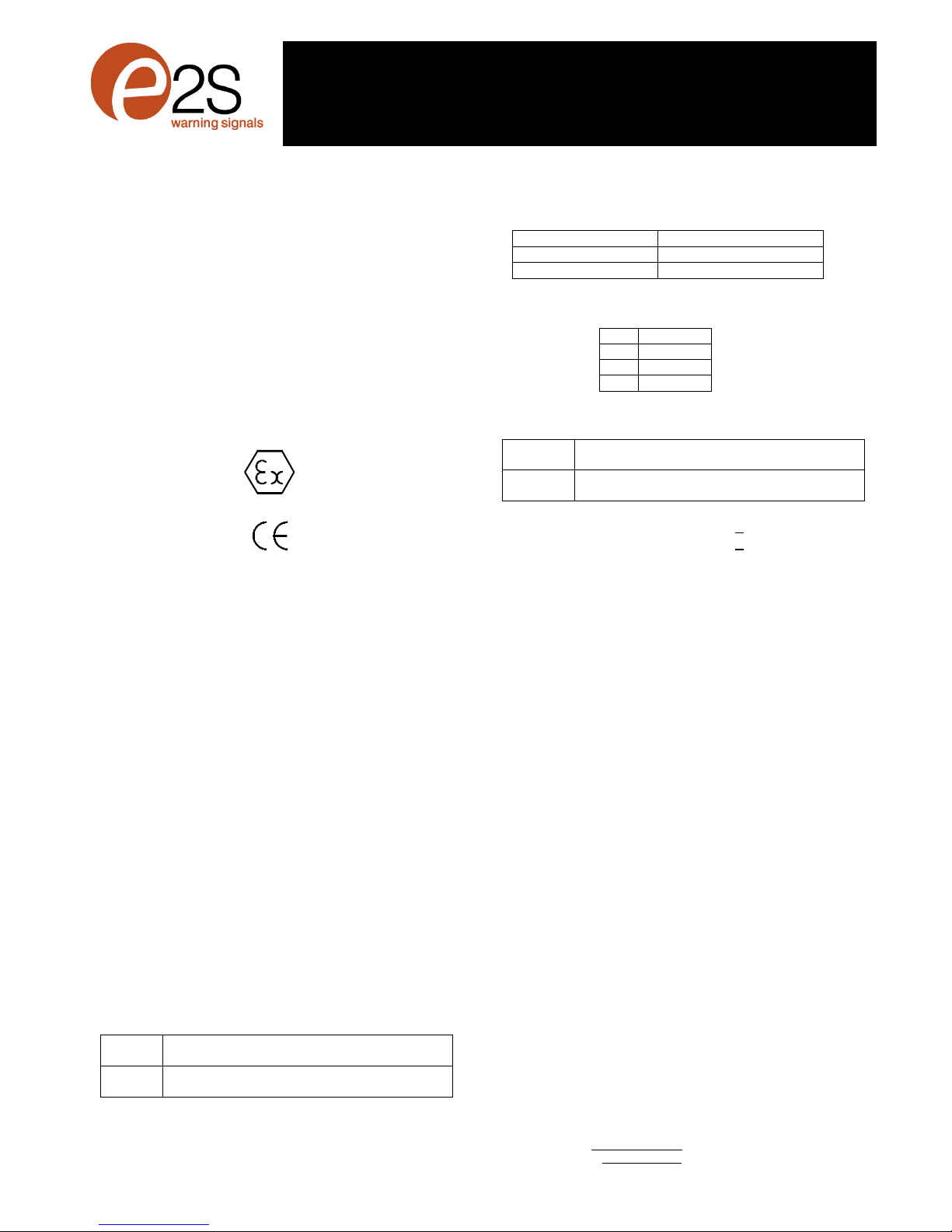
Figure7
Figure6
BEx
D
S110DDC Sounder
BEx
D
S110DAC
Sounder
VolumeControl
DIPSwitch
DIPSwitch
VolumeControl
DC Terminals
StageHeaders
StageTerminals
ACTerminals
S2
S3
-
+
S2
S3
C
N
L
_______________________________________________________________________________________________________________________________
EuropeanSafetySystemsLtd. Impress House, MansellRoad, Acton, London W37QHsales@e-2-s.com Tel: +44 (0)208 743 8880
www.e-2-s.com Fax: +44 (0)208 740 4200
DocumentNo. BExDS120Dand BExDS110D(Gas-Dust)EnglishIssue E(FourSheets)19-02-10 (5)
INSTRUCTION MANUAL(ATEX/IECEx)(GBR)
BExDS120Dand BExDS110DFlameproofSounders
ForuseinFlammableGasand DustAtmospheres
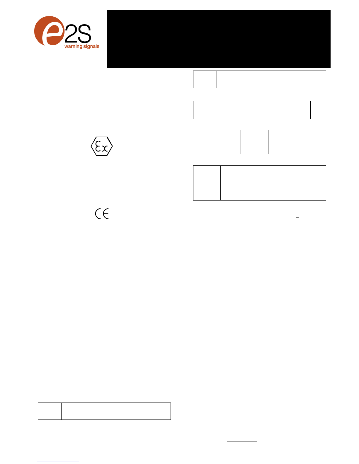
2)Marking
All unitshavearatinglabel,whichcarriesthefollowing
important information:-
UnitType No. BExDS120DorBExDS110D
Input Voltage: DC Units12Vor24Vor48V
ACUnits230Vor110Vor115V
Codes:ExdIICT4forTa–50ºCto+55ºC
ExdIIBT4forTa–50ºCto+70ºC
ExtDA21IP67T115ºCbased onmaxTaof+70ºC
CertificateNo’s KEMA99ATEX6312
IECExKEM10.0003
“Warnings” DONOTOPENWHENANEXPLOSIVE
GAS ORDUSTATMOSPHEREISPRESENT
COVERBOLTSCLASS A4-80
USE HEATRESISTINGCABLES ANDCABLEGLANDS
(Rated 110ºC)ATAMB. TEMPERATURES OVER40ºC
4)Installation Requirements
Soundersmustbeinstalled inaccordancewiththefollowing
orequivalent standards.
EN60079-14:2008 ElectricalInstallationsinHazardous
IEC60079-14:2007 (Ed4) Areas(otherthan mines)
EN60079-10:2003 Classification of HazardousAreas
IEC60079-10:2008 (Ed1)
Installationshouldonlybe carried bycompetent personnel
andanylocalcodesofpracticeapplied.
5)Zones, GasGroup,CategoryandTemperature
Classification
Theunitscan be installed inlocationswiththefollowing
conditions:-
Area Classification Gas:
Zone1
Explosivegasairmixturelikelytooccurin
normaloperation.
Zone2
Explosivegasairmixtu
renotlikelytooccur,
andifit does, it willonlyexist forashort time.
Gas Groupings:
GroupIIA
Propane
GroupIIB
Eth
ylene
GroupIIC
<+55ºC
HydrogenandAcetylene
TemperatureClassification:
T1
400
o
C
T2
300
o
C
T3
200
o
C
T4
135
o
C
Area Classification Dust:
Zone21
Explosivedustairmixturelikelytooccurin
normaloperation.
Zone22
Explosivedustairmi
xturenotlikelytooccur,
andifit does, it willonlyexist forashort time.
IPRating: IP67 T100ºCTa< +55ºC
T115ºCTa< +70ºC
EquipmentCategory: 2G/D
AmbientTemperatureRange:
-50°Cto+55°CGasGroupsIIA,IIBandIIC
-50°Cto+70°CGasGroupIIAandIIB
6)SounderLocation and Mounting
SeedrawingA
7)AccesstotheFlameproofEnclosure
SeedrawingB
Notethefour M6screwsareClassA4-80stainlesssteel
andonlyscrewsofthiscategorycanbeusedonthese
sounders. Itisthereforeimportantthatthesescrewsand
theirspringwashersarekeptinasafeplaceduring
installation.
8)PowerSupplySelection
Thesystempowersupplymusthavethenecessarycapacity
toprovidetheinputcurrenttoall ofthesoundersconnected
tothesystem.
Thefollowingtableshowstheinputcurrenttakenbythe
varioussounderunits:-
UnitType InputInput Max.
VoltageCurrentI/PVolts
BExDS120D 24VDC 800mA 30V
BExDS120D 12VDC 850mA 15V
BExDS120D 48VDC 420mA 58V
BExDS120D 230VAC90mA 264V
0518
II 2G/D
Epsilonx:
Equipment Groupand
Category:
CEMarking:
Notified BodyNo.
_______________________________________________________________________________________________________________________________
EuropeanSafetySystemsLtd. Impress House, MansellRoad, Acton, London W37QHsales@e-2-s.com Tel: +44 (0)208 743 8880
www.e-2-s.com Fax: +44 (0)208 740 4200
DocumentNo. BExDS120Dand BExDS110D(Gas-Dust)EnglishIssue E(FourSheets)19-02-10 (6)
BExDS120D 110VAC200mA 121V
BExDS120D 115VAC180mA 126V
BExDS110D 24VDC 265mA 30V
BExDS110D 12VDC 195mA 15V
BExDS110D 48VDC 130mA 58V
BExDS110D 230VAC56mA 264V
BExDS110D 110VAC93mA 121V
BExDS110D 115VAC110mA 126V
Theabovetablealsoshowsthemaximumvoltagesatwhich
thesounderscan be operated.
9)CableSelection
Cablesmustbe capableofhandlingthecurrentdrawnfrom
all oftheunitsontheline.
SAFETYWARNING: If thehighoutput BExDS120Dsounders
areused athighambienttemperatures,i.e.over+40ºC,then
thecableentrytemperaturemayexceed +70ºCandtherefore
suitableheatresistingcablesmustbeused,witharated
servicetemperatureofat least 110ºC.
10)Earthing
BothACandDC sounderunitsmustbe connectedtoagood
qualityearth.Theunitsareprovided withinternaland
external-earthingterminals,whichare,bothlocated onthe
terminalchambersectionoftheunit(see figures2and3).
Whenusingtheinternalearthterminalensurethatthe
stainless steelM4flatwasherisbetweentheincomingearth
wireandtheenclosure.
Whenusingtheexternalearthterminalacablecrimplug
must be used. Thecablelugshouldbelocatedbetweenthe
twoM5stainless steelflat washers. TheM5stainless steel
springwashermust be fixedbetweentheouterflat washer
andtheM5stainless steelnut toensurethat thecablelugis
secured against looseningandtwisting.
11)CableGlands
TheBExDS120DandBExDS110Dsoundershavedualcable
glandentrieswithM20 x1.5entrythreads.Onlycableglands
approvedforEx‘d’applicationscan be used,whichmustbe
suitableforthetype ofcablebeingusedandalsomeetthe
requirementsoftheEx‘d’flameproofinstallationstandard
EN60079-14:2008/ IEC60079-14:2007.
Whenonlyonecableentryisused theotheronemustbe
closedwithanEx‘d’flameproofblankingplug, whichmust be
suitablyapproved fortheinstallationrequirements.
Forcombustibledustapplications,thecableentrydeviceand
blankingelementsshall be intype ofexplosionprotection
increasedsafety"e"orflameproofenclosure"d"andshall
haveanIP6XratingaccordingtoEN60529:1992.
SAFETYWARNING: If thehighoutput BExDS120Dsounders
areused athighambienttemperatures,i.e.over+40ºC,then
thecableentrytemperaturemayexceed +70ºCandtherefore
suitableheatresistingcableglandsmustbeused,witha
rated servicetemperatureofat least 110ºC.
12)CableConnections
SeedrawingCandD
13) ToneSelection and 2nd and3rdStageAlarms
SeewiringdiagramE
14) Volume Control
SeedrawingF
15) End ofLineMonitoring (DC Units)
OnBExDS120DandBExDS110DDC units,dcreverseline
monitoringcan be usedifrequired.All DC soundershavea
blockingdiode fitted intheirsupplyinputlines.Anendof line
monitoringdiode oran endof linemonitoringresistorcan be
connectedacrossthe+veand–veterminals.If an end of line
resistorisuseditmusthaveaminimumresistancevalueof
3k3ohmsandaminimumwattage of0.5wattsoraminimum
resistancevalueof500 ohmsandamin. wattage of2watts.
TONESELECTIONTABLE
ToneSelection
DIPSwitch
Settings
StageSelection
Stage1
FrequencyDescription
12345
Stage2
Stage3
1
C
ontinuous1000Hz
ToxicGasAlarm
00000
Tone31
Tone11
2
Alternating800/1000Hzat0.25s
intervals
10000
Tone17
Tone5
3
SlowWhoop 500/1200Hzat0.3Hz
with0.5sgaprepeated
01000
Tone2
Tone5
4
Sweeping800/1
000 at1Hz
11000
Tone6
Tone5
5
Continuousat2400Hz
00100
Tone3
Tone27
6
Sweeping2400/2900Hzat7Hz
10100
Tone7
Tone5
7
Sweeping2400/2900Hzat1Hz
01100
Tone10
Tone5
8
Siren500/1200/500Hza
t0.3Hz
11100
Tone2
Tone5
9
Sawtooth1200/500Hzat1Hz
00010
Tone15
Tone2
10
Alternating2400/2900Hzat2Hz
10010
Tone7
Tone5
11
Intermittent1000Hzat0.5Hz
Generalalarm
01010
Tone31
Tone1
1
2
Alternating800/1000Hzat0.875Hz
11010
Tone4
Tone5
13
Intermittent2400Hzat1Hz
00110
Tone15
Tone5
14
Intermittent800Hz0.25son1soff
10110
Tone4
Tone5
15
Continuousat800Hz
01110
Tone2
Tone5
16
Intermittent660Hz150mSon,
150mSoff
11110
Tone18
Tone5
17
Alternating544Hz
(100mS)/440Hz(400mS)
00001
Tone2
Tone27
18
Intermittent660Hz1.8son, 1.8soff
10001
Tone2
Tone5
19
1400Hzto1600Hz
sweepupover
1s-1600Hzto1400Hzsweepdown
over0.5s
01001
Tone2
Tone5
20
Continuous660Hz
11001
Tone2
Tone5
21
Alternating554/440Hzat1Hz
00101
Tone2
Tone5
22
Intermittent554Hzat0.875Hz
10
101
Tone2
Tone5
23
800Hzpulsingat2Hz
01101
Tone6
Tone5
24
Sweeping800/1000Hzat50Hz
11101
Tone29
Tone5
25
Sweeping2400/2900Hzat50Hz
00011
Tone29
Tone5
26
Simulatedbell sound
1001
1
Tone2
Tone1
27
Continuous554Hz
01011
Tone26
Tone5
28
Continuous440Hz
11011
Tone2
Tone5
29
Sweeping800/1000Hzat7Hz
00111
Tone7
Tone5
30
420Hzrepeating0.625son, 0.625s
off Australianalertsignal
10111
Tone32
Tone5
31
1200/500Hzat1Hz
PreparetoAbandon Platform
01111
Tone11
Tone1
32
Sweeping500/1200Hz3.75son,
0.25soff 15Hz
11111
Tone26
Tone1

_______________________________________________________________________________________________________________________________
EuropeanSafetySystemsLtd. Impress House, MansellRoad, Acton, London W37QHsales@e-2-s.com Tel: +44 (0)208 743 8880
www.e-2-s.com Fax: +44 (0)208 740 4200
DocumentNo. BExDS120Dand BExDS110D(Gas-Dust)EnglishIssue E(FourSheets)19-02-10 (7)
Drawing A
Tightenscrewto
secure
Lossen screw
toadjust
Tighten screwtosecure.
Spænd skruen foratfastgøre.
Schroefaandraaien omvasttezetten.
Serrerlavispourunefixation sûre.
ZumSichernSchraube anziehen.
Stringerelaviteperilfissaggio.
Stramskruenforåfeste.
Aperteoparafusoparafixar.
Aprieteeltornilloparaasegurar.
Draåtskruven förattfästa.
Loosen screwtoadjust.
Løsnskruen forattilpasse.
Schroeflosdraaien omaftestellen.
Desserrerlavispourrégler.
ZumRegulieren Schraube lockern.
Allentarelaviteperpotereffettuarela
regolazione.
Løsne skruen foråjustere.
Desaperteoparafusoparaajustar.
Aflojeeltornilloparaajustar.
Lossaskruven föratt justera.
Drawing B
Drawing C
+
-
S3
S2
N
L
C
S3
S2
N
L
+
-
S3
S2
C
S3
S2
BExS120DAC
BExS120DDC
Drawing D
S2
S3
-
+
S2
S3
C
BExS110DAC
BExS110DDC

_______________________________________________________________________________________________________________________________
EuropeanSafetySystemsLtd. Impress House, MansellRoad, Acton, London W37QHsales@e-2-s.com Tel: +44 (0)208 743 8880
www.e-2-s.com Fax: +44 (0)208 740 4200
DocumentNo. BExDS120Dand BExDS110D(Gas-Dust)EnglishIssue E(FourSheets)19-02-10 (8)
Wiring DiagramE
-
S3
S2
+
BExS120D and
BExS110D
DC Units
+- S2S3 +- S2S3 +- S2S3
C
S3
S2
L
N
E
BExS120Dand
BExS110D
ACUnits
CS2S3
N
CS2S3
N
CS2S3
EE
LL
E
N
L
Drawing F
BExS110D
BExS120D
S2
S3
C
C
S3
S2
N
L

_______________________________________________________________________________________________________________________________
EuropeanSafetySystemsLtd. Impress House, MansellRoad, Acton, London W37QHsales@e-2-s.com Tel: +44 (0)208 743 8880
www.e-2-s.com Fax: +44 (0)208 740 4200
DocumentNo. BExDS120Dand BExDS110D(Gas-Dust)DanishIssue E(TwoSheets)19-02-10 (9)
INSTRUKTIONSMANUAL(ATEX/IECEx)(DNK)
BExDS120DogBExDS110D Flammesikresoundere
Til brug i miljøermed brandfarlige gasserog
2)Mærkater
Alleenhederharenklassificeringsmærkat, derbærer
følgendevigtigeoplysninger:
Enhedstypenr. BExDS120DellerBExDS110D
Indgangsspænding: DC-enheder12Veller24Veller48V
AC-enheder230Veller110Veller115V
Kodes:ExdIICT4forTa–50ºCto+55ºC
ExdIIBT4forTa–50ºCto+70ºC
ExtDA21IP67T115ºCbased onmaxTaof+70°C
Certifikatnr. KEMA99ATEX6312
IECExKEM10.0003
”Advarsler” MÅIKKE ÅBNES,
NÅRDEREREKSPLOSIVE
GASSERELLERSTØVTILSTEDE
DÆKBOLTEKLASSEA4-80
BRUGVARMEBESTANDIGEKABLEROGPAKDÅSER
(Mærket110ºC)VEDOMGIVENDETEMP. OVER40ºC
4)Installationskrav
Soundereskalinstalleresioverensstemmelsemedfølgende
ellertilsvarende standarder.
EN60079-14:2008 Elektriskeinstallationerisundheds
IEC60079-14:2007 (Ed4) farlige områder(undtagen miner)
EN60079-10:2003 Klassifikation af sundhedsfarlige om
IEC60079-10:2008 (Ed1) råder
Installationbørkunudføresafkompetent personaleog under
iagttagelseaflokaleregler.
5)Zone-,gasgruppe-,kategori-og temperatur-
klassifikation
Enhedernekan installerespåområdermed følgende forhold:
Klassificeringsareal forgasser:
Zone1
Eksplosivgas
-
ogluftblandingkan forekomme
ved normaldrift.
Zone2
Eksplosivgas
-
ogluftblandingfore
kommer
sandsynligvisikke,oghvisdetsker,vil detkun
væreforenkort tidsperiode.
Gasgrupperinger:
Gruppe IIA
Propan
Gruppe IIB
Ethylen
Gruppe IIC
<+55ºC
Hydrogenogacetylen
Temperaturklassifikation:
T1
400
o
C
T2
300
o
C
T3
200
o
C
T4
135
o
C
Klassificeringsareal forstøv:
Zone21
Eneksplosivblandingafstøvog luft kan
forekommeunderdennormaledrift
Zone22
Eneksplosivblandingafstøvog luft vil
sandsynligvisikkeforekomme, oghvisdette
skulleske, vil det kun vareet kort stykketid.
IPdimensionering: IP67 T100ºCTa< +55ºC
T115ºCTa< +70ºC
Udstyrskategori: 2G/D
Omgivendetemperatur:
-50°Ctil +55°CGasgrupperingerIIA, IIBog IIC
-50°Ctil +70°CGasgrupperingerIIAogIIB
6)Sounderplacering og-montering
SeillustrationA
7)Adgangtil flammesikkerindkapsling
SeillustrationB
Bemærk,atde fire M6skruerer klaseA4-80,rustfristål,
og dermåkunanvendesskruerafdennekategoripå
sounderne.Deterderforvigtigt, atskruerneog deres
fjederskiveropbevarespået sikkert sted underinstallation.
8)Strømforsyningsudvalg
Systemetsstrømforsyningskalhavedennødvendige
kapacitetforatkunneyde indgangsstrømtil allesoundere
forbundet til systemet.
Nedenståendetabelviserindgangsstrømbehovetforforskel-
lige sounderenheder:
Enhedstype Indgangs-Indgangs-Maks.
spænding strøm I/PVolt
BExDS120D 24VDC 800mA 30V
BExDS120D 12VDC 850mA 15V
BExDS120D 48VDC 420mA 58V
BExDS120D 230VAC90mA 264V
BExDS120D 110VAC200mA 121V
BExDS120D 115VAC180mA 126V
0518
II 2G/D
Epsilonx:
Udstyretsgruppe
og kategori:
CE-mærke:
Noteret
myndighedsnr.
_______________________________________________________________________________________________________________________________
EuropeanSafetySystemsLtd. Impress House, MansellRoad, Acton, London W37QHsales@e-2-s.com Tel: +44 (0)208 743 8880
www.e-2-s.com Fax: +44 (0)208 740 4200
DocumentNo. BExDS120Dand BExDS110D(Gas-Dust)DanishIssue E(TwoSheets)19-02-10 (10)
BExDS110D 24VDC 265mA 30V
BExDS110D 12VDC 195mA 15V
BExDS110D 48VDC 130mA 58V
BExDS110D 230VAC56mA 264V
BExDS110D 110VAC93mA 121V
BExDS110D 115VAC110mA 126V
Ovenstående tabelviserogsåmaksimalspændingen,som
soundernekan betjenesved.
9)Kabeludvalg
Kablerneskalkunnehåndteredensamledestrømfraallean-
vendteenheder.
SIKKERHEDSADVARSEL: Hvisde højtydendeBExDS120D-
soundereanvendesvedhøjeomgivendetemperaturer,dvs.
over+40ºC,kan kabletsindgangstemperaturoverstige
+70ºC,ogderskalderforanvendespassende
varmebestandige kablermed ennominelarbejdstemperatur
påmindst 110ºC.
10)Jordforbindelse
Både AC-og DC-sounderenhederskalværeforbundettil en
jordforbindelseafhøjkvalitet. Enhederneharindvendigeog
udvendige jordklemmer,derbegge befindersigpåenhedens
klemkammerdel(sefigur2og3).
Nårdenudvendige jordklemmelanvendes, skalderbruges
enkabelklemmesko. Kabelskoenskalbefinde sigmellemto
flade M5-spændeskiverr afrustfrit stål. DerustfristålM5-
spændeskiverskalfastgøresmellemdenydrefladeskiveog
M5-møtrikkenafrustfrit stålforat sikre, atkabelskoenikke
løsnerellervridersig.
11)Kabelafslutning
SoundernehardobbeltekabelafslutningsindgangemedM20
x1,5indgangsgevind.Kun kabelafslutningergodkendttil Ex
‘d’-applikationermåanvendesog skalpassetil dentype
kabel,deranvendessamtopfyldekraveneiEx‘d’,standard
forflammesikkerinstallationEN60079-14:2008/IEC60079-
14:2007.
Nårderkun anvendesenkabelindgang, skaldenandenluk-
kesmed enEx‘d’, flammesikkerblindprop, derskalvære
korrekt godkendt ioverensstemmelsemedl
installationskravene.
Iforbindelsemed letantændeligestøvapplikationerskal
kabelindføringsanordningenog stansningselementernevære
medeksplosionsbeskyttelseforforhøjet sikkerhed aftype “e”
elleret flammesikkert indelukkeaftype “d”ogskalhaveenIP
6XdimensioneringioverensstemmelsemedEN60529:1992.
SIKKERHEDSADVARSEL: Hvisde højtydendeBExDS120D-
soundereanvendesvedhøjeomgivendetemperaturer,dvs.
temperaturerover+40ºC,kan kabletsindgangstemperatur
overstige+70ºC,og derskalderforanvendespassende
varmebestandige kablermed ennominelarbejdstemperatur
påmindst 110ºC.
12)Kabelforbindelser
SeillustrationenCog D
13) Tonevalg og2.og 3. niveaualarmer
SeledningsdiagramE
14) Volumenkontrol
SeillustrationF
15) Linieslutovervågning (DC-enheder)
PåBExDS120Dog BExDS110DDC-enhederkan der
anvendesreturlinieovervågning,efterbehov.AlleDC-
soundereharenspærrediode istrømindgangsledningerne.
Endiodetil linieslutovervågningellerenlinieslutmodstand
kan forbindespåtværsaf+ve-og –ve-klemmerne.Hvisen
linieslutmodstanderanvendes,skaldenhaveenminimum
modstandsværdipå3k3ohmogetminimumwatt-talpå0,5
watt ellerenminimummodstandsværdipå500 ohmoget
minimumwatt-talpå2watt.
TONEVALGSTABEL
ToneSelection
DIPSwitch
Settings
StageSelection
Stage1
FrequencyDescription
12345
Stage2
Stage3
1
Continuous1000Hz
ToxicGasAlarm
00000
Tone31
Ton
e11
2
Alternating800/1000Hzat0.25s
intervals
10000
Tone17
Tone5
3
SlowWhoop 500/1200Hzat0.3Hz
with0.5sgaprepeated
01000
Tone2
Tone5
4
Sweeping800/1000 at1Hz
11000
Tone6
Tone5
5
Continuousat2400
Hz
00100
Tone3
Tone27
6
Sweeping2400/2900Hzat7Hz
10100
Tone7
Tone5
7
Sweeping2400/2900Hzat1Hz
01100
Tone10
Tone5
8
Siren500/1200/500Hzat0.3Hz
11100
Tone2
Tone5
9
Sawtooth1200/500Hza
t1Hz
00010
Tone15
Tone2
10
Alternating2400/2900Hzat2Hz
10010
Tone7
Tone5
11
Intermittent1000Hzat0.5Hz
Generalalarm
01010
Tone31
Tone1
12
Alternating800/1000Hzat0.875Hz
11010
Tone4
Ton
e5
13
Intermittent2400Hzat1Hz
00110
Tone15
Tone5
14
Intermittent800Hz0.25son 1soff
10110
Tone4
Tone5
15
Continuousat800Hz
01110
Tone2
Tone5
16
Intermittent660Hz150mSon,
150mSoff
1111
0
Tone18
Tone5
17
Alternating544Hz
(100mS)/440Hz(400mS)
00001
Tone2
Tone27
18
Intermittent660Hz1.8son, 1.8soff
10001
Tone2
Tone5
19
1400Hzto1600Hzsweepupover
1s-1600Hzto1400Hzsweepdown
over0.5s
01
001
Tone2
Tone5
20
Continuous660Hz
11001
Tone2
Tone5
21
Alternating554/440Hzat1Hz
00101
Tone2
Tone5
22
Intermittent554Hzat0.875Hz
10101
Tone2
Tone5
23
800Hzpulsingat2Hz
0110
1
Tone6
Tone5
24
Sweeping800/1000Hzat50Hz
11101
Tone29
Tone5
25
Sweeping2400/2900Hzat50Hz
00011
Tone29
Tone5
26
Simulatedbell sound
10011
Tone2
Tone1
27
Continuous554Hz
01011
Tone26
Tone5
28
Continuous440Hz
11011
Tone2
Tone5
29
Sweeping800/1000Hzat7Hz
00111
Tone7
Tone5
30
420Hzrepeating0.625son, 0.625s
off Australianalertsignal
10111
Tone32
Tone5
31
1200/500Hzat1Hz
PreparetoAbandon Platform
01111
Tone11
Tone1
32
Sweeping500/1200Hz3.75son,
0.25soff 15Hz
11111
Tone26
Tone1
_______________________________________________________________________________________________________________________________
EuropeanSafetySystemsLtd. Impress House, MansellRoad, Acton, London W37QHsales@e-2-s.com Tel: +44 (0)208 743 8880
www.e-2-s.com Fax: +44 (0)208 740 4200
DocumentNo. BExDS120Dand BExDS110D(Gas-Dust)DutchIssue E(TwoSheets)19-02-10 (11)
INSTRUCTIEHANDLEIDING(ATEX/IECEx)(NLD)
BExDS120DenBExDS110DVuurvastealarmgevers
Voorgebruikin
brandbaregas- en stofatmosferen
2)Labels
Alleeenhedenzijnvoorzienvan eenlabel,waarop de
volgendebelangrijkeinformatiestaat:
Typenr. eenheid: BExDS120Dof BExDS110D
Ingangsspanning: DC-eenheden12Vof24 Vof48 V
AC-eenheden230Vof110Vof115V
Codes:ExdIICT4forTa–50ºCto+55ºC
ExdIIBT4forTa–50ºCto+70ºC
ExtDA21IP67T115ºCbased onmaxTaof+70°C
CertificateNo. KEMA99ATEX6312
IECExKEM10.0003
“Waarschuwingen” NIETOPENENWANNEER
EREENEXPLOSIEVE GAS-
OFSTOFATMOSFEERAANWEZIGIS
DEKSELBOUTENKLASSE A4-80
BIJOMGEVINGSTEMP. HOGERDAN40ºC
HITTEBESTENDIGEKABELSENKABELWARTELS
GEBRUIKEN(geschiktvoor110ºC)
4)Vereistenvoorinstallatie
Alarmgeversmoetenwordengeïnstalleerdin
overeenstemmingmet de volgendeofequivalentenormen.
EN60079-14:2008 Elektrische installatiesingevaarlijke
IEC60079-14:2007 (Ed4) omgevingen (andersdan mijnen)
EN60079-10:2003 Classificatievan gevaarlijke
IEC60079-10:2008 (Ed1) omgevingen
Installatiemagalleenwordenuitgevoerddoordeskundig
personeelenmet inachtnemingvan plaatselijke
gedragscodesenpraktijkrichtlijnen.
5)Classificatiet.a.v.zones,gasgroep, categorie
en temperatuur
Deeenhedenkunnenwordengeïnstalleerdopplaatsenwaar
de volgendeomstandighedenheersen:
Zoneclassificatiegas:
Zone1
Ontplofbaargas
-
/luchtmengseliswaarschijnlijk
bij normaalbedrijf.
Zone2
Ontplofbaargas
-
/luchtmengselis
onwaarschijnlijk, enindiendit ontstaat zalhet
waarschijnlijkslechtskortetijdaanwezig
blijven.
Gasgroeperingen:
GroepIIA
Propaan
GroepIIB
Ethyleen
GroepIIC
<+55ºC
Waterstofenacetyleen
Temperatuurclassificatie:
T1
400
o
C
T2
300
o
C
T3
200
o
C
T4
135
o
C
Zoneclassificatiestof:
Zone21
Explosiefstof
-
luchtmengselwaarschijnlijk
aanwezigbij normaalfunctioneren.
Zone22
Explosiefstof
-
luchtmengselwaarschijnlijkniet
aanwezig, ofalleenvan korteduur.
IP-classificatie:IP67 T100ºCTa< +55ºC
T115ºCTa< +70ºC
Categorievanapparatuur: 2G/D
Omgevingstemperatuur:
-50°Ctot +55°CGasgroeperingenIIA, IIBenIIC
-50°Ctot +70°CGasgroeperingenIIAenIIB
6)Plaatsing enbevestiging vanalarmgever
Zie tekening A
7)Toegang totdevuurvastebehuizing
ZietekeningB
Houdtuerrekeningmee datde vier M6-schroevenvan
KlasseA4-80 roestvrij staalzijnendatopdeze
alarmgeversalleenschroevenvandezecategorie
kunnenwordengebruikt. Hetisderhalvebelangrijkdat
dezeschroevenendebijbehorende veerringentijdensde
installatieop eenveilige plaatswordenbewaard.
8)Kiezenvanvoedingsbron
Devoedingsbronvan hetsysteemdientvoldoende capaciteit
tehebbenomallealarmgeversdieophetsysteemzijn
aangeslotenvan elektrischevoedingtevoorzien.
Indeonderstaande tabelstaatvermeldwelkeingangsstroom
de verschillende alarmgeverstrekken:
Typeeenheid Ingangs-Ingangs-Max.
spanningstroom I/Pvolt
BExDS120D 24 VDC 800 mA30 V
BExDS120D 12 VDC 850 mA15 V
BExDS120D 48 VDC 420 mA58 V
0518
II 2G/D
Epsilonx:
Groepencategorie
van apparatuur:
CE
-
certificaat:
Instantienr.

_______________________________________________________________________________________________________________________________
EuropeanSafetySystemsLtd. Impress House, MansellRoad, Acton, London W37QHsales@e-2-s.com Tel: +44 (0)208 743 8880
www.e-2-s.com Fax: +44 (0)208 740 4200
DocumentNo. BExDS120Dand BExDS110D(Gas-Dust)DutchIssue E(TwoSheets)19-02-10 (12)
BExDS120D 230 VAC90 mA 264 V
BExDS120D 110 VAC200 mA121 V
BExDS120D 115 VAC180 mA126 V
BExDS110D 24 VDC 265 mA30 V
BExDS110D 12 VDC 195 mA15 V
BExDS110D 48 VDC 130 mA58 V
BExDS110D 230 VAC56 mA 264 V
BExDS110D 110 VAC93 mA 121 V
BExDS110D 115 VAC110 mA126 V
Inde bovenstaande tabelwordttevensvermeldopwelke
maximumspanningende alarmgeverskunnenwerken.
9)Kiezenvankabels
Kabelsmoetenbestandzijntegendestroomdiedooralle
eenhedenop de lijnwordt getrokken.
VEILIGHEIDSWAARSCHUWING: alsde BExDS120D
alarmgeversmethogeuitvoerwordengebruiktbij hoge
omgevingstemperaturen,m.a.w.hogerdan +40ºC,dan kan
detemperatuurbij dekabelinganghogerzijndan +70ºCen
moetendusgeschiktehittebestendigekabelsworden
gebruikt, meteennominalewerktemperatuurvantenminste
110ºC.
10)Aarding
Zowelalarmgeversopwisselstroomalsgelijkstroommoeten
wordenaangeslotenopaardingvangoedekwaliteit. De
eenhedenwordengeleverdmetinterneenexterne
aardaansluitingen, beide aangebracht op het gedeeltemetde
aansluitkast op de eenheid(zieAfb. 2en3).
Bij gebruikvan de externeaardaansluitingdient een
kabelkrimpkoustewordengebruikt. Dekabelkousmoet
wordenaangebracht tussende tweeM5roestvrijstalenplatte
borgschijfjes. DeM5roestvrijstalenveerringmoet worden
bevestigdtussenhet buitensteplatteborgschijfjeende M5
roestvrijstalenmoer, zodat de kabelkousgoed isvastgezet
enniet kandraaienoflosraken.
11)Kabelwartels
Dealarmgeverszijnvoorzienvan dubbele
kabelwartelingangenmetM20 x1,5ingangsschroefdraad.Er
kunnenalleenkabelwartelswordengebruiktdiezijn
goedgekeurdvoorEx‘d’-toepassingen,geschiktzijnvoorhet
bekabelingstype datwordtgebruiktenvoldoenaan de
vereistenvan de normEN60079-14:2008/IEC60079-
14:2007 tenaanzienvande Ex‘d’vuurvasteinstallatie.
Indienslechtseenkabelingangwordtgebruikt, dientde
anderetewordenafgeslotenmeteenEx‘d’vuurvaste
afdichtplug,diemoetzijngoedgekeurdvoorde
installatievereisten.
Voorbrandbarestoftoepassingenzullende kabelinvoeren
blokkeerelementenvan het type explosiebeschermingmet
verhoogde beveiliging“e”ofvuurvasteomhulling“d”zijnen
eenIP6X-classificatiehebbenovereenkomstig
EN60529:1992.
VEILIGHEIDSWAARSCHUWING: alsde BExDS120D
alarmgeversmethogeuitvoerwordengebruiktbij hoge
omgevingstemperaturen,m.a.w.hogerdan +40ºC,dan kan
detemperatuurbij dekabelinganghogerzijndan +70ºCen
moetendusgeschiktehittebestendigekabelwartelsworden
gebruikt, meteennominalewerktemperatuurvantenminste
110ºC.
12)Kabelaansluitingen
ZietekeningCenD
13) Toonkeuzeenalarmenin 2e en3e fase
ZiebedradingsschemaE
14) Volumeregeling
ZietekeningF
15) Bewaking aaneindevan lijn (DC-eenheden)
OpBExDS120DenBExDS110DDC-eenhedenkan
desgewenstomgekeerdegelijkstroomlijnbewakingworden
gebruikt. AlleDC-alarmgeverszijnuitgerustmeteen
blokkeringsdiode inde ingangslijnenvoordeelektrische
voeding.Eenbewakingsdiodeofbewakingsweerstandaan
heteindevan de lijnkan wordenaangeslotenopde +veen–
vecontacten. Indieneenweerstandaan heteinde van de lijn
wordtgebruikt, dientdezeeenminimumweerstandswaarde
van 3k3ohmeneenminimumwattage van 0,5watt te
hebben,of eenminimumweerstandswaarde van 500 ohmen
eenminimumwattage van2watt.
TABELVOORTOONKEUZE
ToneSelection
DIPSwitch
Settings
StageSelection
Stage1
FrequencyDescription
12345
Stage2
Stage3
1
Continuous1000Hz
ToxicGasAlarm
0
0000
Tone31
Tone11
2
Alternating800/1000Hzat0.25s
intervals
10000
Tone17
Tone5
3
SlowWhoop 500/1200Hzat0.3Hz
with0.5sgaprepeated
01000
To
ne2
Tone5
4
Sweeping800/1000 at1Hz
11000
Tone6
T
one5
5
Continuousat2400Hz
00100
Tone3
Tone27
6
Sweeping2400/2900Hzat7Hz
10100
Tone7
Tone5
7
Sweeping2400/2900Hzat1Hz
01100
Tone10
To
ne5
8
Siren500/1200/500Hzat0.3Hz
11100
Tone2
Tone
5
9
Sawtooth1200/500Hzat1Hz
00010
Tone15
Tone2
10
Alternating2400/2900Hzat2Hz
10010
Tone7
Tone5
11
Intermittent1000Hzat0.5Hz
Generalalarm
01010
Tone31
Tone1
12
Alternating800/1000Hzat0.875Hz
1
1010
Tone4
Tone5
13
Intermittent2400Hzat1Hz
00110
Tone15
Tone5
14
Intermittent800Hz0.25son 1soff
10110
Tone4
Tone5
15
Continuousat800Hz
01110
Tone2
Tone5
16
Intermittent660Hz150mSon
,
150mSoff
11110
Tone18
Tone5
17
Alternating544Hz
(100mS)/440Hz(400mS)
00001
Tone2
Tone27
18
Intermittent660Hz1.8son, 1.8soff
10001
Tone2
Tone5
19
1400Hzto1600Hzsweepupover
1s-1600Hzto1400Hzsweepdown
over0.5s
01001
Tone2
Tone5
20
Continuous660Hz
11001
Tone2
Tone5
21
Alternating554/440Hzat1Hz
00101
Tone2
Tone5
22
Intermittent554Hzat0.875Hz
10101
Tone2
Tone5
23
800Hzpuls
ingat2Hz
01101
Tone6
Tone5
24
Sweeping800/1000Hzat50Hz
11101
Tone2
9
Tone5
25
Sweeping2400/2900Hzat50Hz
00011
Tone29
Tone5
26
Simulatedbell sound
10011
Tone2
Tone1
27
Continuous554Hz
01011
Tone26
Tone5
28
Continuous440Hz
11011
Tone
2
Tone5
29
Sweeping800/1000Hzat7Hz
00111
Tone7
Tone5
30
420Hzrepeating0.625son, 0.625s
off Australianalertsignal
10111
Tone32
Tone5
31
1200/500Hzat1Hz
PreparetoAbandon Platform
01111
Tone11
Tone1
32
Sweeping500/1200Hz3.75son,
0.25soff 15Hz
11111
Tone26
Tone1

_______________________________________________________________________________________________________________________________
EuropeanSafetySystemsLtd. Impress House, MansellRoad, Acton, London W37QHsales@e-2-s.com Tel: +44 (0)208 743 8880
www.e-2-s.com Fax: +44 (0)208 740 4200
DocumentNo. BExDS120Dand BExDS110D(Gas-Dust)FrenchIssue E(TwoSheets)19-02-10 (13)
MANUELD’UTILISATION(ATEX
/
IECEx
)
(F
RA
)
Alarmessonoresantidéflagrantes
BExDS120DetBExDS110D
Pourune utilisation dansdesatmosphèrespoussiéreuses
etcontenantdesgaz
inflammables
2)Marquage
Lescaractéristiquesnominalesdetouteslesunitésfigurent
suruneétiquettecomportantlesinformationsimportantes
suivantes:
N°de type d’unité: BExDS120DouBExDS110D
Tensiond’entrée : UnitésCC 12V, 24Vou48 V
UnitésCA230 V,110Vou115 V
Codes:ExdIICT4forTa–50ºCto+55ºC
ExdIIBT4forTa–50ºCto+70ºC
ExtDA21IP67T115ºCbased onmaxTaof+70ºC
CertificateNo. KEMA99ATEX6312
IECExKEM10.0003
Avertissements NEPAS OUVRIRENPRESENCED’UN
GAZ
EXPLOSIFOUDANSUNEATMOSPHERE
POUSSIEREUSE
BOULONSDECOUVERCLEDECLASSE A4-80
UTILISERDES CABLES ETDES PRESSE-ETOUPE
RESISTANTSALACHALEUR(Valeurnominale110ºC)
ADES TEMPERATURES AMBIANTES
SUPERIEURES A40ºC
4)Spécificationsd’installation
Lesalarmessonoresdoiventêtreinstalléesselonlesnormes
suivantes, oudeséquivalents.
EN60079-14:20008 Installationsélectriquesdansdes
IEC60079-14:2007 (Ed4) zonesdangereuses(autresque des
mines)
EN60079-10:2003 Classification deszonesdangereuses
IEC60079-10:2008 (Ed1)
L’installationdoit êtreeffectuée uniquement parun personnel
compétent et conformément auxcodesdepratiquelocaux.
5)Classification deszones,du groupeetdela
catégoriedegazetdes températures
Lesunitéspeuventêtreinstalléesdansdesendroits
respectant lesconditionssuivantes:
Classification dezone:gaz:
Zone1
Mélange d’airet de gazexplosifpouvant
survenirenconditionnormale.
Zone2
Mélange d’airet de gazexplosifnepouvant
passurveniret qui, danslecascontraire,
serait présent quetrèsbrièvement.
Groupesdegaz:
Groupe IIA
Propane
Groupe IIB
Ethylène
Groupe IIC
<+55ºC
Hydrogèneet Acétylène
Classification destempératures :
T1
400
o
C
T2
300
o
C
T3
200
o
C
T4
135
o
C
Classification deszones :poussière:
Zone21
Mél
ange air
-
poussièreexplosifsusceptible
de seformerdurant lecoursnormaldes
opérations
Zone22
Mélange air
-
poussièreexplosifnon
susceptiblede seformeret qui, s’il seforme,
nesubsisterapaslongtemps.
IndiceIP: IP67 T100ºCTa< +55ºC
T115ºCTa< +70ºC
Classedel’équipement: 2G/D
Plagedetempératuresambiantes:
-50°Cà+55°CGroupesdegazIIA, IIBet IIC
-50°Cà+70°CGroupesdegazIIAetIIB
6)Assemblageetemplacementdel’alarme sonore
SereporterauschémaA
7)Accèsauboîtierantidéflagrant
Sereporterau schémaB
Remarque: lesquatre visM6sontenacierinoxydablede
classeA4-80etseules des visdecetypedoiventêtre
utiliséessurcesalarmes sonores. C’estpourquoiil est
importantde lesconserver,ainsiqueleursrondellesà
ressort, enun endroit sûrpendant l’installation.
8)Sélection del’alimentation électrique
L’alimentationélectriquedusystèmedoitposséderla
capaciténécessairepourprocurerlecourantd’entréeà
touteslesalarmessonoresconnectéesau système.
Le tableau suivantindiquelecourantd’entrée pourles
diversesunitésd’alarmesonore:
II 2G/D
Epsilonx
:
Groupe et classe
de l’équipement :
0518
Marquage CE
:
N°de l’organismenotifié

_______________________________________________________________________________________________________________________________
EuropeanSafetySystemsLtd. Impress House, MansellRoad, Acton, London W37QHsales@e-2-s.com Tel: +44 (0)208 743 8880
www.e-2-s.com Fax: +44 (0)208 740 4200
DocumentNo. BExDS120Dand BExDS110D(Gas-Dust)FrenchIssue E(TwoSheets)19-02-10 (14)
Typed’unité TensionCourantVoltsI/P
d'entrée d’entrée max.
BExDS120D 24 VCC 800 mA30 V
BExDS120D 12 VCC 850 mA15 V
BExDS120D 48 VCC 420 mA58 V
BExDS120D 230 VCA90 mA 264 V
BExDS120D 110 VCA200 mA121 V
BExDS120D 115 VCA180 mA126 V
BExDS110D 24 VCC 265 mA30 V
BExDS110D 12 VCC 195 mA15 V
BExDS110D 48 VCC 130 mA58 V
BExDS110D 230 VCA56 mA 264 V
BExDS110D 110 VCA93 mA 121 V
BExDS110D 115 VCA110 mA126 V
Le tableau ci-dessusindiqueégalementlestensions
maximalesde fonctionnement desalarmessonores.
9)Sélection descâbles
Lescâblesdoiventpouvoirprendreencharge lecourant
utilisépartouteslesunitéssurlaligne.
AVERTISSEMENTDESECURITE: silesalarmessonores
BExDS120Dàhautrendementsontutiliséesàdes
températuresambiantesélevées,c’est-à-diresupérieuresà
+40ºC,latempératured’entrée ducâblepeutexcéder+70ºC
etdescâblesrésistantsàlachaleurdoiventêtreutilisés,
d’unetempératurede serviceassignéede110ºCminimum.
10)Mise àlaterre
Lesunitésd’alarmesonoreCAetCC doiventêtre
connectéesàun systèmede miseàlaterrede bonnequalité.
Lesunitéssontfourniesavecdesbornesdemiseàlaterre
externeetinternequisonttouteslesdeuxsituéessurla
sectiondechambreterminaledel’unité(sereporteraux
figures2et3).
Lorsde l’utilisationde labornedemiseàlaterreexterne,
employerunecosseàsertir. Lacosseàsertirdoit êtresituée
entrelesdeuxrondellesplatesM5enacierinoxydable. La
rondelleàressort M5enacierinoxydabledoit êtrefixée entre
larondelleplateexterneet l’écrouM5enacierinoxydable
afinquelacosseàsertirnesedesserreninesetorde.
11)Presse-étoupe
Lesalarmessonoresontdeuxentréesde presse-étoupe
avecdesfiletagesd'entréeM20x1,5.Seulslespresse-
étoupeapprouvéspourlesapplicationsEx‘d’peuventêtre
utilisés,etilsdoiventêtreadéquatspourletype de câble
utiliséetrépondreauxexigencesd'installation
d’antidéflagrantEx‘d’denormeEN60079-14:2008/
IEC60079-14:2007.
Lorsqu’uneseuleentréedecâbleestutilisée,un bouchon
obturateurantidéflagrantEx‘d’,répondantauxexigences
d’installation,doit êtreappliquésurl’autreentrée.
Pourlesapplicationsavecprésencedepoussière
combustible, ledispositifd’entréedecâbleet lesobturateurs
requièrent un type de protectionantidéflagranteaccrue«e»
ouun boîtierignifugé«d»et doivent présenterun indicede
protectionIP6XconformeàEN60529:1992.
AVERTISSEMENTDESECURITE: silesalarmessonores
BExDS120Dàhautrendementsontutiliséesàdes
températuresambiantesélevées,c’est-à-diresupérieuresà
+40ºC,latempératured’entrée ducâblepeutexcéder+70ºC
etdescâblesrésistantsàlachaleurdoiventêtreutilisés,
d’unetempératurede serviceassignéede110ºCminimum.
12)Connexionsdecâble
Sereporterau schémaCet D
13) Sélection dutimbreetalarmes de2ème et3ème
étape
Sereporterau schémade câblage E
14) Contrôledu volume
Sereporterau schémaF
15) Contrôledefin deligne(Unités CC)
SurlesunitésCC BExDS120DetBExDS110D,un contrôle
de ligneinverseccpeutêtreutilisésinécessaire.Toutesles
alarmessonoresCCpossèdentunediodede blocage
installée surleurligned’entrée d’alimentation.Unediodede
contrôlede finde ligneouunerésistancedecontrôledefin
de lignepeutêtreconnectée surlesbornespositiveet
négative.Encasd’utilisationd’unerésistancede findeligne,
celle-cidoitavoirunevaleurde résistanceminimumde3k3
ohmsetunepuissanceminimumde 0,5watt ouune
résistanceminimumde 500ohmsainsiqu’unepuissance
minimumde 2watts.
TABLEAUDESELECTIONDUTIMBRE
ToneSelection
DIPSwitch
Settings
StageSelection
Stage1
FrequencyDescription
12345
Stage2
Stage3
1
Continuous1000Hz
ToxicGasAlarm
00000
Tone31
Tone11
2
Alternating800/1000H
zat0.25s
intervals
10000
Tone17
Tone5
3
SlowWhoop 500/1200Hzat0.3Hz
with0.5sgaprepeated
01000
Tone2
Tone5
4
Sweeping800/1000 at1Hz
11000
Tone6
Tone5
5
Continuousat2400Hz
00100
Tone3
Tone27
6
Sweeping2400/2900Hzat7Hz
10100
Tone7
Tone5
7
Sweeping2400/2900Hzat1Hz
01100
Tone10
Tone5
8
Siren500/1200/500Hzat0.3Hz
11100
Tone2
Tone5
9
Sawtooth1200/500Hzat1Hz
00010
Tone
15
Tone2
10
Alternating2400/2900Hzat2Hz
10010
Tone7
Tone5
11
Intermittent1000Hzat0.5Hz
Generalalarm
01010
Tone31
Tone1
12
Alternating800/1000Hzat0.875Hz
11010
Tone4
Tone5
13
Intermittent2400Hza
t1Hz
00110
Tone15
Tone5
14
Intermittent800Hz0.25son 1soff
10110
Tone4
Tone5
15
Continuousat800Hz
01110
Tone2
Tone5
16
Intermittent660Hz150mSon,
150mSoff
11110
Tone18
Tone5
17
Altern
ating544Hz
(100mS)/440Hz(400mS)
00001
Tone2
Tone27
18
Intermittent660Hz1.8son, 1.8soff
10001
Tone2
Tone5
19
1400Hzto1600Hzsweepupover
1s-1600Hzto1400Hzsweepdown
over0.5s
01001
Tone2
Tone5
2
0
Continuous660Hz
11001
Tone2
Tone5
21
Alternating554/440Hzat1Hz
00101
Tone2
Tone5
22
Intermittent554Hzat0.875Hz
10101
Tone2
Tone5
23
800Hzpulsingat2Hz
01101
Tone6
Tone5
24
Sweeping
800/1000Hzat50Hz
11101
Tone29
Tone5
25
Sweeping2400/2900Hzat50Hz
00011
Tone29
Tone5
26
Simulatedbell sound
10011
Tone2
Tone1
27
Continuous554Hz
01011
Tone26
Tone5
28
Continuous440Hz
1
1011
Tone2
Tone5
29
Sweeping800/1000Hzat7Hz
00111
Tone7
Tone5
30
420Hzrepeating0.625son, 0.625s
off Australianalertsignal
10111
Tone32
Tone5
31
1200/500Hzat1Hz
PreparetoAbandon Platform
01
111
Tone11
Tone1
32
Sweeping500/1200Hz3.75son,
0.25soff 15Hz
11111
Tone26
Tone1
_______________________________________________________________________________________________________________________________
EuropeanSafetySystemsLtd. Impress House, MansellRoad, Acton, London W37QHsales@e-2-s.com Tel: +44 (0)208 743 8880
www.e-2-s.com Fax: +44 (0)208 740 4200
DocumentNo. BExDS120Dand BExDS110D(Gas-Dust)German Issue E(TwoSheets)19-02-10 (15)
TECHNISCHEHINWEISE(ATEX/IECEx)(DEU)
BExDS120Dund BExDS110D
SchwerentflammbareSounder
ZumEinsatzinentflammbaren Gas- und
Staubatmosphären
2)Kennzeichnung
AlleGerätesindmiteinemTypenschildmitdenfolgenden
wichtigenInformationenversehen:-
Gerätetyp-Nr. BExDS120DoderBExDS110D
Eingangsspannung:
Gleichstromgeräte(DC)12V,24Voder48V
Wechselstromgeräte(AC)230V, 110Voder115V
Codes:ExdIICT4forTa–50ºCto+55ºC
ExdIIBT4forTa–50ºCto+70ºC
ExtDA21IP67T115ºCbased onmaxTaof+70ºC
CertificateNo. KEMA99ATEX6312
IECExKEM10.0003
Warnung NICHTINEXPLOSIONSFÄHIGENGAS-ODER
STAUBATMOSPHÄRENÖFFNEN
ABDECKSCHRAUBENKLASSE A4-80
WÄRMEBESTÄNDIGEKABELUND
KABELFLANSCHEVERWENDEN
(Nennleistung 110ºC)BEI UMGEB.-TEMP. ÜBER40ºC
4)Installationsanforderungen
DieSoundermüssengemäßdenfolgendenoder
vergleichbarenStandardsinstalliertwerden.
EN60079-14:2008 Elektrische Installationen in
IEC60079-14:2007 (Ed4) Gefahrenbereichen (außer
Bergwerken)
EN60079-10:2003 Klassifizierung von Gefahrenbereichen
IEC60079-10:2008 (Ed1)
DieInstallationsolltenurvonqualifiziertemFachpersonal
vorgenommenwerden. ÖrtlicheanerkannteVerfahrensind
zubeachten.
5)Zonen, Gasgruppe, Kategorieund
Temperaturklassifizierung
DieGerätekönnenanStandortenaufgestelltwerden,an
denendiefolgendenBedingungenvorliegen:-
Bereichseinteilung Gas:
Zone1
BeinormalemBetriebkann mithoher
Wahrscheinlichkeit eineexplosiveGas-Luft-
Mischungvorliegen.
Zone2
ExplosiveGas
-
Luft
-
Mischungunwa
hrschein
-
lichundsolltesiedochauftreten, dann nur
kurzfristig.
Gasgruppen:
Gruppe IIA
Propan
Gruppe IIB
Äthylen
Gruppe IIC
<+55ºC
WasserstoffundAzetylen
Temperaturklassifizierung:
T1
400
o
C
T2
300
o
C
T3
200
o
C
T4
135
o
C
Bereichseinteilung Staub:
Zone21
ExplosionsgefährdetesStaub
-
/Luftgemisch,
dasbeimnormalenBetriebdurchaus
auftretenkann
Zone22
ExplosionsgefährdetesStaub
-
/Luftgemisch,
dessenAuftretenunwahrscheinlichbzw. von
kurzerDauerist.
IP-Schutzklasse:IP67 T100ºCTa< +55ºC
T115ºCTa< +70ºC
Gerätekategorie:2G/D
Umgebungstemperaturbereich:
-50°Cbis+55°CGasgruppenIIA, IIBundIIC
-50°Cbis+70°CGasgruppenIIAundIIB
6)Sounder-Standortund Montage
SieheZeichnung A
7)Zugang zumschwerentflammbarenGehäuse
SieheZeichnungB
Hinweis:Dievier SchraubenM6sind ausEdelstahlKlasse
A4-80 gefertigt.FürdieseSoundersindnurSchrauben
dieserKategoriegeeignet. DieseSchraubenunddie
zugehörigenFederringe sindbeimEinbau dahersorgfältig
aufzubewahren.
8)Stromversorgung
DieStromversorgungderAnlage mussausreichen,umalle
angeschlossenenSoundermit Eingangsstromzuversorgen.
FolgendeTabellezeigt denvondenverschiedenenSounder-
GerätenentnommenenEingangsstrom:-
Gerätetyp Eingangs- Eingangs-Max. I/P
Spannung strom Spannung
BExDS120D 24VDC 800 mA30V
BExDS120D 12VDC 850 mA15V
BExDS120D 48VDC 420 mA58V
BExDS120D 230VAC90 mA 264V
BExDS120D 110VAC200 mA121V
BExDS120D 115VAC180 mA126V
BExDS110D 24VDC 265 mA30V
0518
II 2G/D
Epsilonx:
Gerätegruppe und
–kategorie:
CE
-
Kennzeichnung:/
Bekannt gegebeneNr.
_______________________________________________________________________________________________________________________________
EuropeanSafetySystemsLtd. Impress House, MansellRoad, Acton, London W37QHsales@e-2-s.com Tel: +44 (0)208 743 8880
www.e-2-s.com Fax: +44 (0)208 740 4200
DocumentNo. BExDS120Dand BExDS110D(Gas-Dust)German Issue E(TwoSheets)19-02-10 (16)
BExDS110D 12VDC 195 mA15V
BExDS110D 48VDC 130 mA58V
BExDS110D 230VAC56 mA 264V
BExDS110D 110VAC93 mA 121V
BExDS110D 115VAC110 mA126V
ObigeTabellezeigtauchdiemaximaleSpannungan,mitder
dieSounderbetriebenwerdenkönnen.
9)Kabelwahl
DieKabelmüssendenStromallerangeschlossenenGeräte
führenkönnen.
SICHERHEITSHINWEIS: Wenn dieBExDS120DHigh-
Output-SounderbeihohenUmgebungstemperaturen
eingesetzt werden(d. h. beiüber+40ºC), kann die
Kabeleingangstemperatur+70ºCübersteigen. Dahersind
geeignetehitzebeständige Kabelmit einer
Nennbetriebstemperaturvonmindestens110ºCzu
verwenden.
10)Erdung
DieWechsel-undGleichstrom-Soundergerätemüssenmit
einerhochwertigenErdungverbundenwerden. DieGeräte
sindmit internenundexternenErdklemmen(am
Klemmkammerteil desGeräts, sieheAbb. 2und3)versehen.
BeiVerwendungderexternenErdklemmeist ein
Quetschkabelschuh zuverwenden, derzwischendenbeiden
flachenM5-Edelstahl-Unterlegscheibeneingesetzt werden
sollte. DieM5-Unterlegscheibensindzwischenderäußeren
flachenUnterlegscheibeundderM5-Edelstahlmutter
einzusetzen, umzugewährleisten, dass derKabelschuh sich
nicht lösenoderverdrehenkann.
11)Kabelflansche
DieSoundersindmit doppeltenKabelflanscheingängenmit
EingangsgewindenvonM20 x1.5versehen. Esdürfennur
Kabelflanscheverwendet werden, diefürEx‘d’-
Anwendungenzugelassensind. DieKabelflanschemüssen
fürdeneingesetztenKabeltypgeeignet seinundzudemden
AnforderungenderEx‘d’-NormzurInstallationschwer
entflammbarerGeräteEN60079-14:2008 / IEC60079-
14:2007 entsprechen.
Wenn nureinKabeleingangverwendet wird, muss der
anderemit einemschwerentflammbarenEx‘d’
Handlochverschluss, derfürdieInstallationsbedingungen
zugelassenist, verschlossenwerden.
BeiAnwendungeninbrennbarenStaubbereichensindder
KabelanschlussunddieAbdeckelementeineinemGehäuse
mit erhöhtemExplosionsschutz(Typ„e“)odererhöhtem
Entflammbarkeitsschutz(„Typ„d“)zuinstallierenundmüssen
derSchutzklasseIP6XgemäßEN60529:1992 entsprechen.
SICHERHEITSHINWEIS: Wenn dieBExDS120DHigh-
Output-SounderbeihohenUmgebungstemperaturen
eingesetzt werden(d. h. beiüber+40ºC), kann die
Kabeleingangstemperatur+70ºCübersteigen. Dahersind
geeignetehitzebeständige Kabelflanschemit einer
Nennbetriebstemperaturvonmindestens110ºCzu
verwenden.
12)Kabelanschlüsse
SieheZeichnungCundD
13) Tonwahlund Alarmder2.und3.Stufe
SieheSchaltbildE
14) Lautstärkeregulierung
SieheZeichnungF
15) Überwachung desLeitungsendes
(Gleichstromgeräte)
BeiBExS120D-undBExS110D-Gleichstromgerätenkann bei
BedarfeineWechselstrom-Sperrleitungskontrolleeingesetzt
werden.AlleGleichstrom-SoundersindmiteinerSperrdiode
versehen,dieindieSpeise-Eingangsleitungeneingesetztist.
EineÜberwachungsdiodeodereinKontrollwiderstandfürdas
LeitungsendekönnenüberdieKlemmen+veund–ve
miteinanderverbundenwerden.WirdeinWiderstandfürdas
Leitungsende verwendet, muss seinWiderstandswert
mindestens3k3OhmunddieMindestleistung0,5Watt
betragen,oderaberesmusseinWiderstandswertvon
mindestens500 OhmundeineMindestleistungvon2Watt
vorliegen.
TONEVALGSTABEL
ToneSelection
DIPSwitch
Settings
StageSelection
Stage1
FrequencyDescription
12345
Stage2
Stage3
1
Continuous1000Hz
ToxicGasAlarm
00000
Tone31
Tone11
2
Alternating800/1000Hzat0.25s
intervals
10000
Tone17
Tone5
3
SlowWhoop 500/1200Hzat
0.3Hz
with0.5sgaprepeated
01000
Tone2
Tone5
4
Sweeping800/1000 at1Hz
11000
Tone6
Tone5
5
Continuousat2400Hz
00100
Tone3
Tone27
6
Sweeping2400/2900Hzat7Hz
10100
Tone7
Tone5
7
Sweeping
2400/2900Hzat1Hz
01100
Tone10
Tone5
8
Siren500/1200/500Hzat0.3Hz
11100
Tone2
Tone5
9
Sawtooth1200/500Hzat1Hz
00010
Tone15
Tone2
10
Alternating2400/2900Hzat2Hz
10010
Tone7
Tone5
11
Intermittent1000Hzat0.5Hz
Generalalarm
01010
Tone31
Tone1
12
Alternating800/1000Hzat0.875Hz
11010
Tone4
Tone5
13
Intermittent2400Hzat1Hz
00110
Tone15
Tone5
14
Intermittent800Hz0.25son 1soff
1
0110
Tone4
Tone5
15
Continuousat800Hz
01110
Tone2
Tone5
16
Intermittent660Hz150mSon,
150mSoff
11110
Tone18
Tone5
17
Alternating544Hz
(100mS)/440Hz(400mS)
00001
Tone2
Tone27
18
Intermitten
t660Hz1.8son, 1.8soff
10001
Tone2
Tone5
19
1400Hzto1600Hzsweepupover
1s-1600Hzto1400Hzsweepdown
over0.5s
01001
Tone2
Tone5
20
Continuous660Hz
11001
Tone2
Tone5
21
Alternating554/440Hzat1
Hz
00101
Tone2
Tone5
22
Intermittent554Hzat0.875Hz
10101
Tone2
Tone5
23
800Hzpulsingat2Hz
01101
Tone6
Tone5
24
Sweeping800/1000Hzat50Hz
11101
Tone29
Tone5
25
Sweeping2400/2900Hzat5
0Hz
00011
Tone29
Tone5
26
Simulatedbell sound
10011
Tone2
Tone1
27
Continuous554Hz
01011
Tone26
Tone5
28
Continuous440Hz
11011
Tone2
Tone5
29
Sweeping800/1000Hzat7Hz
00111
T
one7
Tone5
30
420Hzrepeating0.625son, 0.625s
off Australianalertsignal
10111
Tone32
Tone5
31
1200/500Hzat1Hz
PreparetoAbandon Platform
01111
Tone11
Tone1
32
Sweeping500/1200Hz3.75son,
0.25soff 15Hz
11
111
Tone26
Tone1

_______________________________________________________________________________________________________________________________
EuropeanSafetySystemsLtd. Impress House, MansellRoad, Acton, London W37QHsales@e-2-s.com Tel: +44 (0)208 743 8880
www.e-2-s.com Fax: +44 (0)208 740 4200
DocumentNo. BExDS120Dand BExDS110D(Gas-Dust)ItalianIssue E(TwoSheets)19-02-10 (17)
MANUALEDIISTRUZIONI(ATEX/IECEx)(ITA)
Sirene antincendio BExDS120D e BExDS110D
Perl'utilizzoinatmosferedi gasepolveri infiammabili
2)Marchio
Tutteleunitàsonodotatedietichettacontenenteleseguenti
importantiinformazioni:-
N. tipo unitàBExDS120DoBExDS110D
Tensioneiningresso: UnitàCC 12 Vo24 Vo48V
UnitàCA230 Vo110 Vo115 V
Codice:ExdIICT4forTa–50ºCto+55ºC
ExdIIBT4forTa–50ºCto+70ºC
ExtDA21IP67T115ºCbased onmaxTaof+70ºC
N. certificato KEMA99ATEX6312
IECExKEM10.0003
“Attenzione” NONAPRIREINCASODI PRESENZADI
GAS OPOLVERI ESPLOSIVE
COPRIREI BULLONI CONUNACOPERTURA
CLASSE A4-80
USARECAVI EPREMISTOPPA PERCAVI RESISTENTI AL
CALORE(temp. nominale110°C)SE LA
TEMPERATURAAMB. ÈSUPERIOREA40°C
4)Requisitidiinstallazione
Le sirenedevonoessereinstallateinconformitàconi
seguentistandardostandardequivalenti.
EN60079-14:2008 Installazionielettriche inaree
IEC60079-14:2007 (Ed4) pericolose(tranne che nelleminiere)
EN60079-10:2003 Classificazione dellearee pericolose
IEC60079-10:2008 (Ed1)
L'installazionedeveessereeseguitadapersonale
competenteedevonoessereapplicatituttiicodici
professionali l°Cali.
5)Classificazionedellezone, deigruppidigas,
dellecategorieedelletemperature
Le unitàpossonoessereinstallateinambientiche
presentanoleseguenticondizioni:-
ClassificazioneareaGas:
Zona 1
Èprobabilelapresenzadigasesplosivo
duranteil normalefunzionamento.
Zona 2
Nonèprobabilechesiapresentegas
esplosivo, eseessodovesseesserepresente,
potràesserlosoloperun breveperiododi
tempo.
Gruppidigas:
Gruppo IIA
Propano
Gruppo IIB
Etilene
Gruppo IIC
<+55ºC
IdrogenoeAcetilene
Classificazionedelletemperature:
T1
400
°
C
T2
300
°
C
T3
200
°
C
T4
135
°
C
ClassificazioneareaPolvere:
Zona 21
Probabileformazionedimisceleesplosive
polvere/ariaduranteilnormale
funzionamento.
Zona 22
Improbabileformazione, eventualmentesolo
temporanea, dimisceleesplosive
polvere/aria.
ClassificazioneIP: IP67 T100ºCTa< +55ºC
T115ºCTa< +70ºC
Categoriadi attrezzature: 2G/D
Intervallodellatemperaturaambientale:
da-50 °C a+55 °C GruppidigasIIA,IIBeIIC
da-50 °C a+70 °C GruppidigasIIAeIIB
6)Posizioneemontaggio dellesirene
VederefiguraA
7)Accessoalsistemaantincendio
VederefiguraB
Le quattro vitiM6sono inacciaioinossidabileclasse
A4-80;suquestesirenepossonoessereusatesoloviti di
questacategoria. Quindièimportantechequestevitiele
relativerondelleamollasianoconservateinun luogo sicuro
durantel'installazione.
8)Sceltadell'alimentazione
L'alimentazionedeveessereingrado difornireuna corrente
iningressoatuttelesirenecollegatealsistema.
Laseguentetabellamostralacorrenteiningressoprelevata
davarieunitàsirene:-
Tipo unità TensioneCorrenteVoltI/P
iningresso iningresso max.
BExDS120D 24 VCC 800 mA30 V
BExDS120D 12 VCC 850 mA15 V
BExDS120D 48 VCC 420 mA58 V
0518
II 2G/D
MarchioCE:
N. notifica
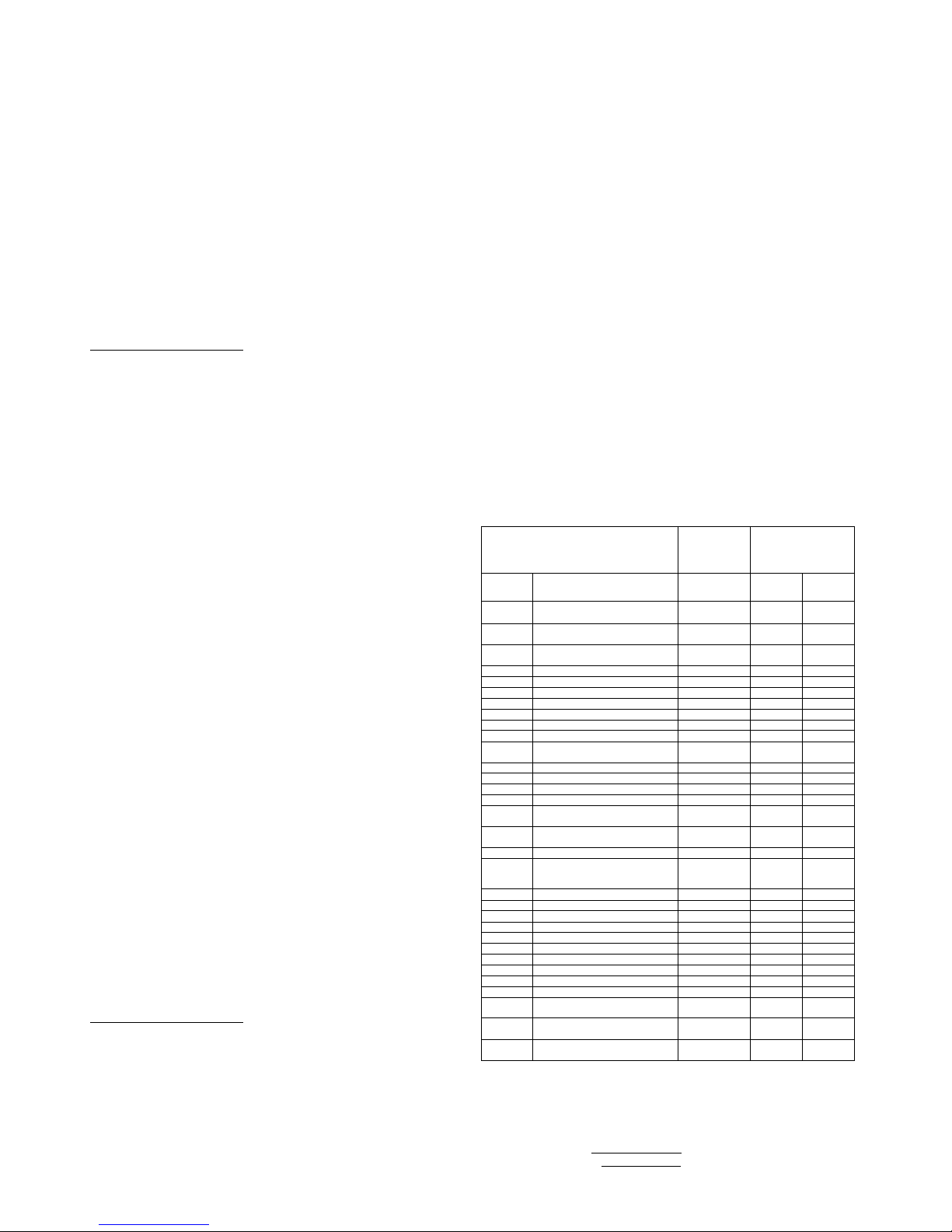
_______________________________________________________________________________________________________________________________
EuropeanSafetySystemsLtd. Impress House, MansellRoad, Acton, London W37QHsales@e-2-s.com Tel: +44 (0)208 743 8880
www.e-2-s.com Fax: +44 (0)208 740 4200
DocumentNo. BExDS120Dand BExDS110D(Gas-Dust)ItalianIssue E(TwoSheets)19-02-10 (18)
BExDS120D 230 VCA90 mA 264 V
BExDS120D 110 VCA200 mA121 V
BExDS120D 115 VCA180 mA126 V
BExDS110D 24 VCC 265 mA30 V
BExDS110D 12 VCC 195 mA15 V
BExDS110D 48 VCC 130 mA58 V
BExDS110D 230 VCA56 mA 264 V
BExDS110D 110 VCA93 mA 121 V
BExDS110D 115 VCA110 mA126 V
Latabellasoprariportatamostrainoltreletensionimassime
previsteperil funzionamentodellesirene.
9)Sceltadeicavi
Icavidevonoesserecapacidisostenerelacorrente
provenientedatutteleunitàpresentisullalinea.
AVVISODISICUREZZA: SelesireneBExDS120Dadalta
emissionevengonoutilizzateinambientiatemperature
elevate,adesempiosuperioria+40 °C,latemperaturain
ingressodeicavipuòsuperare+70°C,percuioccorre
utilizzarecaviadeguatiresistentialcalore,conuna
temperaturanominaledieserciziodialmeno110 °C.
10)Collegamentoditerra
SialeunitàsireneCAsiaquelleCCdevonoesserecollegate
correttamenteaterra.Le unitàvengonoforniteconmorsetti
dicollegamentoaterrainternied esterni,entrambisituati
sullamorsettieradell'unità(vederefigure2e3).
Quando siutilizzailmorsettodicollegamentoaterraesterno,
occorreutilizzareuncapocordaaggraffatopercavi. Il
capocordadeveesserepostotraduerondellepiattein
acciaioinossidabileM5. Larondellaamollainacciaio
inossidabileM5deveesserefissatatralarondellapiatta
esterna eil dado inacciaioinossidabileM5, inmodo da
garantirecheil capocordasiafissatosaldamenteeche
quindinonpossaallentarsioattorcigliarsi.
11)Premistoppapercavi
Le sirenesonodotatedidueingressiperpremistoppacon
filettatureM20 x1.5.Utilizzaresolopremistoppaapprovatiper
leapplicazioniEx'd';essiinoltredevonoessereadeguatial
tipo dicavoinusoedevonorispettaregli standarddi
installazioneantincendioEx'd'EN60079-14:2008 /
IEC60079-14:2007.
Quando siutilizzasoloun ingressopercavi,l'altroingresso
deveesserechiusoconun maschiodichiusuraantincendio
Ex‘d’chedeveessereapprovatoperirequisitidi
installazione.
Perapplicazioniinpresenzadipolvericombustibili, il
dispositivodiingressodelcavoegli elementidiprotezione
devonoessereditipo"e"conprotezionesuperiorecontrole
esplosionioditipo"d"conchiusuraantideflagrantee
presentareuna classificazioneIP6XconformeallanormaEN
60529:1992.
AVVISODISICUREZZA: SelesireneBExDS120Dadalta
emissionevengonoutilizzateinambientiatemperature
elevate,adesempiosuperioria+40 °C,latemperaturain
ingressodeicavipuòsuperare+70°C,percuioccorre
utilizzarepremistoppaadeguatiresistentialcalore,conuna
temperaturanominaledieserciziodialmeno110 °C.
12)Connessionideicavi
VederefiguraCeD
13) Sceltadeltono eallarmidisecondo eterzo
livello
VedereloschemadeicollegamentielettriciE
14) Controllo delvolume
VederefiguraF
15) Sistema dicontrollo difinelinea (unitàCC)
SulleunitàCC BExS120DeBExS110D,serichiesto,è
possibileutilizzareil sistemadicontrollodellalineadi
inversioneCC.TuttelesireneCCsonodotatediun diodo di
bloccaggionellelineediingressodell'alimentazione.È
possibilecollegareaimorsettipositivoenegativoun diodoo
un resistoredicontrollodifinelinea.Sevieneutilizzatoun
resistoredifinelinea,questodeveavereun valoredi
resistenzaminimodi33kohmed un wattaggiominimodi
0,5Woppureun valorediresistenzaminimodi500 ohmed
un wattaggiominimodi2W.
TABELLADISELEZIONEDEITONI
ToneSelection
DIPSwitch
Settings
StageSelection
Stage1
FrequencyDescription
12345
Stage2
Stage3
1
Continuous1000Hz
ToxicGasAlarm
00000
Tone31
Tone11
2
Alternating800/1000Hzat0.25s
intervals
10000
Tone17
Tone5
3
SlowWhoop
500/1200Hzat0.3Hz
with0.5sgaprepeated
01000
Tone2
Tone5
4
Sweeping800/1000 at1Hz
11000
Tone6
Tone5
5
Continuousat2400Hz
00100
Tone3
Tone27
6
Sweeping2400/2900Hzat7Hz
10100
Tone7
Tone
5
7
Sweeping2400/2900Hzat1Hz
01100
Tone10
Tone5
8
Siren500/1200/500Hzat0.3Hz
11100
Tone2
Tone5
9
Sawtooth1200/500Hzat1Hz
00010
Tone15
Tone2
10
Alternating2400/2900Hzat2Hz
10010
Tone
7
Tone5
11
Intermittent1000Hzat0.5Hz
Generalalarm
01010
Tone31
Tone1
12
Alternating800/1000Hzat0.875Hz
11010
Tone4
Tone5
13
Intermittent2400Hzat1Hz
00110
Tone15
Tone5
14
Intermittent800Hz0.25s
on 1soff
10110
Tone4
Tone5
15
Continuousat800Hz
01110
Tone2
Tone5
16
Intermittent660Hz150mSon,
150mSoff
11110
Tone18
Tone5
17
Alternating544Hz
(100mS)/440Hz(400mS)
00001
Tone2
Tone27
18
Intermittent660Hz1.8son, 1.8soff
10001
Tone2
Tone5
19
1400Hzto1600Hzsweepupover
1s-1600Hzto1400Hzsweepdown
over0.5s
01001
Tone2
Tone5
20
Continuous660Hz
11001
Tone2
Tone5
21
Alternating
554/440Hzat1Hz
00101
Tone2
Tone5
22
Intermittent554Hzat0.875Hz
10101
Tone2
Tone5
23
800Hzpulsingat2Hz
01101
Tone6
Tone5
24
Sweeping800/1000Hzat50Hz
11101
Tone29
Tone5
25
Sweeping24
00/2900Hzat50Hz
00011
Tone29
Tone5
26
Simulatedbell sound
10011
Tone2
Tone1
27
Continuous554Hz
01011
Tone26
Tone5
28
Continuous440Hz
11011
Tone2
Tone5
29
Sweeping800/1000Hzat7Hz
00
111
Tone7
Tone5
30
420Hzrepeating0.625son, 0.625s
off Australianalertsignal
10111
Tone32
Tone5
31
1200/500Hzat1Hz
PreparetoAbandon Platform
01111
Tone11
Tone1
32
Sweeping500/1200Hz3.75son,
0.25soff 15Hz
11111
Tone26
Tone1
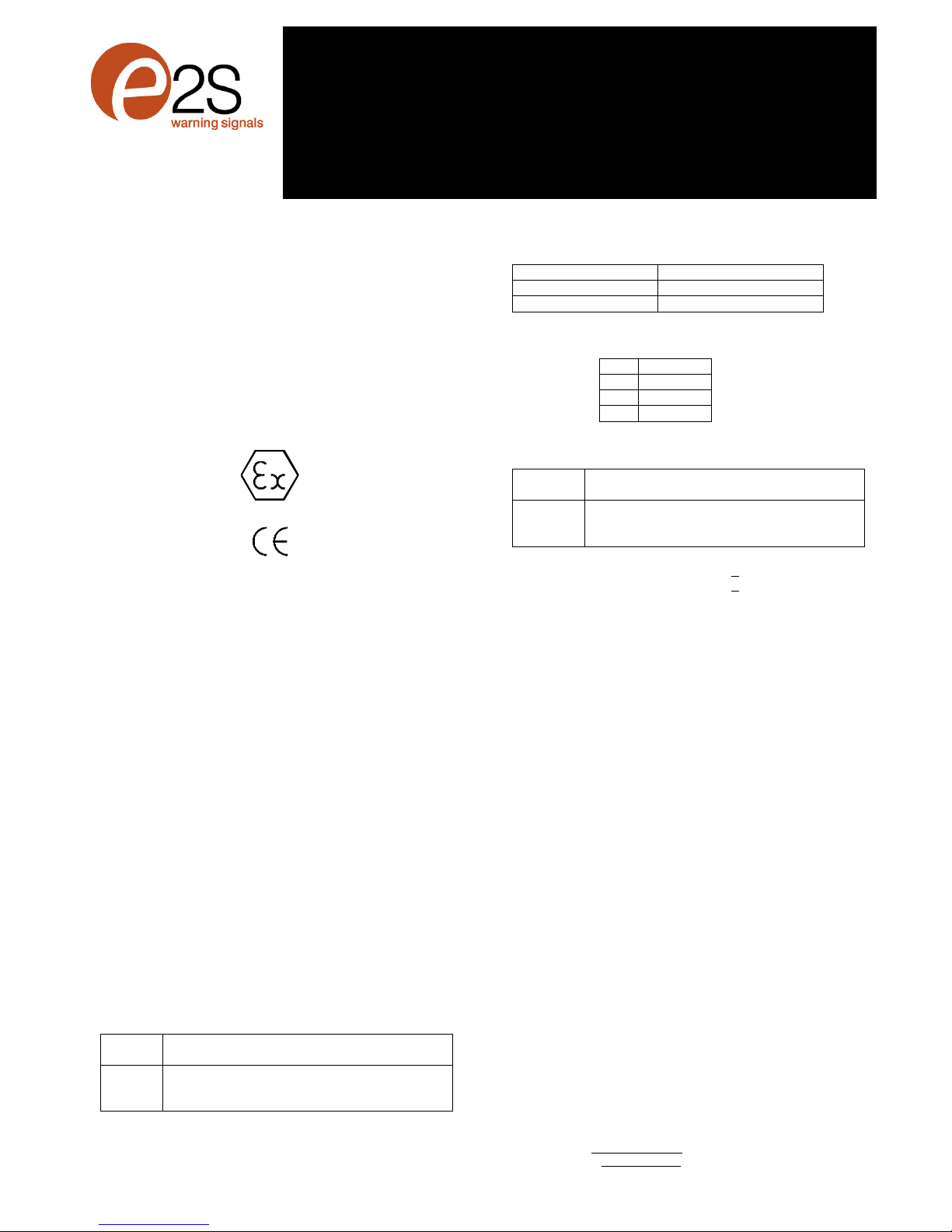
_______________________________________________________________________________________________________________________________
EuropeanSafetySystemsLtd. Impress House, MansellRoad, Acton, London W37QHsales@e-2-s.com Tel: +44 (0)208 743 8880
www.e-2-s.com Fax: +44 (0)208 740 4200
DocumentNo. BExDS120Dand BExDS110D(Gas-Dust)Norwegian Issue E(TwoSheets)19-02-10 (19)
INSTRUKSJONSHÅNDBOK (ATEX/IECEx)(NOR)
BExDS120Dog BExDS110D
Flammesikre lydalarmer
Forbruki atmosfærermedbrennbar
gass og brennbart støv
2)Merking
Alleenheterharenetikett med følgende viktige informasjon:
Enhetstypenr. BExDS120DellerBExDS110D
Inngangsspenning: DC-enheter12 Veller24 Veller48V
AC-enheter230Veller110 Veller115 V
Kode: ExdIICT4forTa–50ºCto+55ºC
ExdIIBT4forTa–50ºCto+70ºC
ExtDA21IP67T115ºCbased onmaxTaof+70ºC
Sertifikat nr. KEMA99ATEX6312
IECExKEM10.0003
“Advarsler” MÅIKKE ÅPNES I ATMOSFÆRE
MEDEKSPLOSIVGASS
ELLEREKSPLOSIVTSTØV
DEKKEBOLTERKLASSE A4-80
BRUKVARMEBESTANDIGEKABLEROG
KABELMUFFER(godkjentfor110ºC)VED
OMGIVELSESTEMPERATUREROVER40ºC
4)Installasjonskrav
Lydalarmermåinstalleresisamsvarmed følgendeeller
tilsvarende standarder.
EN60079-14:2008 Elektriskeinstallasjonerifarlige
IEC60079-14:2007 (Ed4) områder(unntatt gruver)
EN60079-10:2003 Klassifisering avfarlige områder
IEC60079-10:2008 (Ed1)
Installeringmåkunutføresavkompetentepersoner, og alle
gjeldendelokalebransjestandardermåoverholdes.
5)Soner,gassgruppe,kategoriog temperatur
klassifisering
Enhetenekan installerespåstedermed følgende forhold:
Soneklassifisering, gass:
Sone1
Eksplosivgass/luft
-
blandingsomsannsynligvis
forekommerved normaldrift.
Sone2
Eksplosivgass/luft
-
blandingsomikkevanligvis
vil forekomme, ogomdengjørdet, kun vil
forekommeikort tid.
Gassgrupperinger:
Gruppe IIA
Propan
Gruppe IIB
Etylen
Gruppe IIC
<+55ºC
Hydrogenogacetylen
Temperaturklassifisering:
T1
400
o
C
T2
300
o
C
T3
200
o
C
T4
135
o
C
Soneklassifisering, støv:
Sone21
Eksplosivstøv/luft
-
blandingvil sannsynligvis
opptreved normalbruk.
Sone22
Eksplosivstøv/luft
-
blandingvil sannsynligvis
ikkeopptre, oghvisdetskjer, vil denkun
foreliggeikort tid.
IP-klasse: IP67 T100ºCTa< +55ºC
T115ºCTa< +70ºC
Utstyrskategori: 2G/D
Omgivelsestemperaturområde:
-50°Ctil +55°CGassgrupperingerIIA,IIBogIIC
-50°Ctil +70°CGassgrupperingerIIAog IIB
6)Plassering og montering avlydalarmen
Setegningen. A
7)Tilgang til flammesikkerthus
Setegningen. B
Merk:Defire M6-skrueneeravrustfritt stålklasseA4-80,
og kun skrueridennekategorienkanbrukes til disse
lydalarmene. Derforerdetviktigatdisseskruenemed
tilhørende fjærskiveroppbevarespåetsikkertstedunder
installeringen.
8)Valg avstrømtilførsel
Strømtilførselentil systemetmåha nødvendigkapasitettil å
giinngangsstrømtil allelydalarmenesomerkoplettil
systemet.
Følgendetabell viserinngangsstrømmensombenyttesavde
forskjellige lydalarmenhetene:
0518
II 2G/D
Epsilonx:
Utstyrsgruppe og –
kategori:
CE
-
me
rking:
Varslet organ nr.
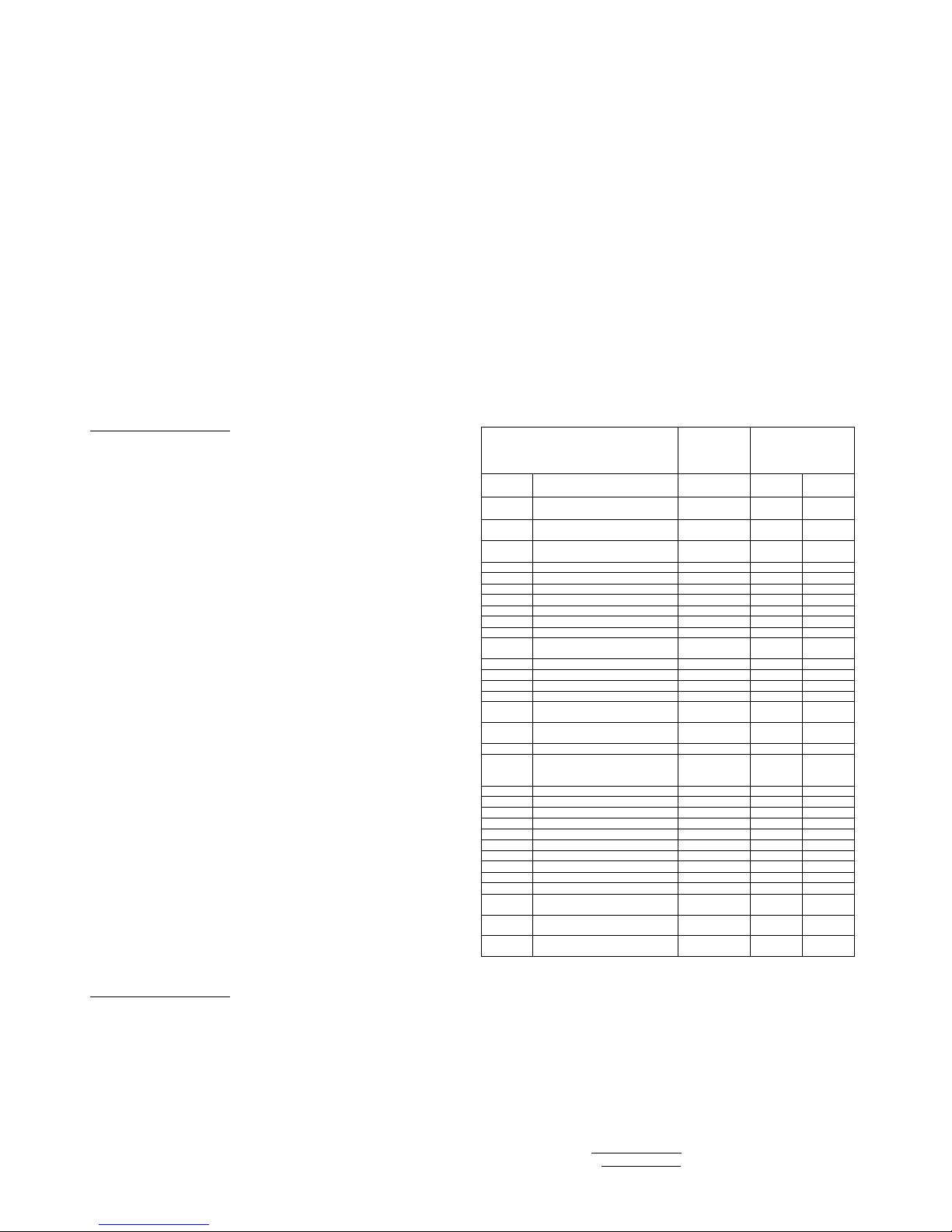
_______________________________________________________________________________________________________________________________
EuropeanSafetySystemsLtd. Impress House, MansellRoad, Acton, London W37QHsales@e-2-s.com Tel: +44 (0)208 743 8880
www.e-2-s.com Fax: +44 (0)208 740 4200
DocumentNo. BExDS120Dand BExDS110D(Gas-Dust)Norwegian Issue E(TwoSheets)19-02-20 (20)
Enhetstype Inngangs- Inngangs- Maks
spenningstrøm I/Pvolt
BExDS120D 24 VDC 800 mA30 V
BExDS120D 12 VDC 850 mA15 V
BExDS120D 48 VDC 420 mA58 V
BExDS120D 230 VAC90 mA 264 V
BExDS120D 110 VAC200 mA121 V
BExDS120D 115 VAC180 mA126 V
BExDS110D 24 VDC 265 mA30 V
BExDS110D 12 VDC 195 mA15 V
BExDS110D 48 VDC 130 mA58 V
BExDS110D 230 VAC56 mA 264 V
BExDS110D 110 VAC93 mA 121 V
BExDS110D 115 VAC110 mA126 V
Tabellenovenforviserogsåmaksimalespenningersom
lydalarmenekanbenyttesved.
10)Valg avkabler
Kablene måkunnehåndterestrømmensomtrekkesfraalle
enhetenepålinjen.
SIKKERHETSVARSEL: Hvishøyeffektsalarmene
BExDS120Dbenyttesved høyeomgivelsestemperaturer,
dvs. over+40ºCkan kabelinngangstemperaturenoverstige
+70 ºC, og derformåegnedevarmebestandigekabler
benyttes, med godkjent driftstemperaturpåminst 95 ºC.
11)Jording
Både AC-ogDC-alarmenhetermåkoplestil jordforbindelse
avgod kvalitet. Enheteneleveresmedinterneogeksterne
jordingsterminaler,sombeggesitterpåterminalkammerdelen
avenheten(sefigur2og3).
Vedbrukaveksternejordterminalermåenbenytteen
kabelkrympesko.Kabelskoenskalsettesmellomdetoflate
M5-fjærskiveneavrustfritt stål.M5-fjærskivenmåfestes
mellomdenytreflateskivenog M5-mutterenavrustfritt stål
foråsikreat kabelskoenikkekanløsnesellervris.
12)Kabelmuffer
Lydalarmenehardoblekabelmuffeinngangermed M20x1,5
inngangsgjenger.Kun kabelmuffergodkjentforEx‘d’-bruk
kanbrukes,og de måværeegnetfortypenkabelsom
brukes,samtoverholdekraveneistandardenforEx‘d’
flammesikkerinstallering,EN60079-14:2008/IEC60079-
14:2007.
Nårkunénkabelinngangbenyttes, mådenandrelukkesmed
enEx‘d’flammesikkerlukkeplugg, sommåværegodkjent for
de aktuelleinstallasjonskravene.
Forbrukmed brennbart støvskalkabelinnføringsenhetenog
tetningsdeleneværeavtypenmed økt eksplosjonssikkerhet
“e”ellerflammesikkerkapsling“d”, og denskalha IP6X-
klasseifølgeEN60529:1992.
SIKKERHETSVARSEL: HvislydalarmeneBExDS120Dmed
høyeffektbrukesved høyeomgivelsestemperaturer,dvs.
over+40 ºC,kankabelinngangstemperaturenoverstige +70
ºC,og derformåegnedevarmebestandige kabelmuffer
benyttes, med godkjent driftstemperaturpåminst 95 ºC.
13)Kabelforbindelser
Setegningen. Cog D
14) Tonevalg og2.-og 3.-trinnsalarmer
Sekablingsskjemaet. E
15) Volumkontroll
Setegningen. F
16) Slutt pålinje-overvåking (DC-enheter)
PåBExDS120D- og BExDS110DDC-enheter,kan
likestrømsreversertlinjeovervåkingbenyttesomnødvendig.
AlleDC-alarmerharenblokkeringsdiode monterti
inngangslinjene.Enslutt pålinje-overvåkingsdiode ellerslutt
pålinje-overvåkingsresistorkan koblesover+ve-og-ve-
terminalene.Hvisenslutt pålinje-resistorbenyttes,måden
ha minstemotstandsverdi3k3ohm,ogminstewattverdi0,5
watt,ellerminstemotstandsverdi500ohmog minste
wattverdi2watt.
TONEVALGTABELL
ToneSelection
DIPSwitch
Settings
StageSelection
Stage1
FrequencyDescription
12345
Stage2
Stage3
1
Continuous1000Hz
ToxicGasAlarm
00000
Tone31
Tone11
2
Alternating800/1000Hzat0.25s
intervals
10000
Tone17
Tone5
3
SlowWhoop 500/1200Hzat0.3Hz
with0.5sgaprepeated
01000
Tone2
Tone5
4
Sweeping800/1000 at1Hz
11
000
Tone6
Tone5
5
Continuousat2400Hz
00100
Tone3
Tone27
6
Sweeping2400/2900Hzat7Hz
10100
Tone7
Tone5
7
Sweeping2400/2900Hzat1Hz
01100
Tone10
Tone5
8
Siren500/1200/500Hzat0.3Hz
111
00
Tone2
Tone5
9
Sawtooth1200/500Hzat1Hz
00010
Tone15
Tone2
10
Alternating2400/2900Hzat2Hz
10010
Tone7
Tone5
11
Intermittent1000Hzat0.5Hz
Generalalarm
01010
Tone31
Tone1
12
Alternating800/10
00Hzat0.875Hz
11010
Tone4
Tone5
13
Intermittent2400Hzat1Hz
00110
Tone15
Tone5
14
Intermittent800Hz0.25son 1soff
10110
Tone4
Tone5
15
Continuousat800Hz
01110
Tone2
Tone5
16
Intermitt
ent660Hz150mSon,
150mSoff
11110
Tone18
Tone5
17
Alternating544Hz
(100mS)/440Hz(400mS)
00001
Tone2
Tone27
18
Intermittent660Hz1.8son, 1.8soff
10001
Tone2
Tone5
19
1400Hzto1600Hzsweepupover
1s-1600Hzto1400Hzsweepdown
over0.5s
01001
Tone2
Tone5
20
Continuous660Hz
11001
Tone2
Tone5
21
Alternating554/440Hzat1Hz
00101
Tone2
Tone5
22
Intermittent554Hzat0.875Hz
10101
Tone2
Ton
e5
23
800Hzpulsingat2Hz
01101
Tone6
Tone5
24
Sweeping800/1000Hzat50Hz
11101
Tone29
Tone5
25
Sweeping2400/2900Hzat50Hz
00011
Tone29
Tone5
26
Simulatedbell sound
10011
Tone2
Tone1
27
Continuous554Hz
01011
Tone26
Tone5
28
Continuous440Hz
11011
Tone2
Tone5
29
Sweeping800/1000Hzat7Hz
00111
Tone7
Tone5
30
420Hzrepeating0.625son, 0.625s
off Australianalertsignal
10111
Tone32
Tone5
31
1200/500Hzat1Hz
PreparetoAbandon Platform
01111
Tone11
Tone1
32
Sweeping500/1200Hz3.75son,
0.25soff 15Hz
11111
Tone26
Tone1
This manual suits for next models
1
Table of contents
Languages:
Other Incite Fire Marine Equipment manuals


