Webasto Cool Top 23 RT-E User manual

Installation Instructions
Rooftop Parking Cooler
Model:Cool Top 23 RT-E
Installation & Operation Instructions
English Version (V1)

Improper installation or maintenance of the rooftop parking air conditioner may cause
adverse consequences, which may cause damage to vehicle components.
To install and maintain rooftop parking cooler, Webasto training courses, corresponding
technical documents, professional tools and special equipments are required.
Only Webasto's original accessories are allowed.
Forbid to conduct Installation and maintenance of the product without completion of
Webasto training, lacking of corresponding qualification for working on air conditioning
system or necessary technical documents, tools and outfits
Read and comply with warnings and notes in these installation and operation instructions
of this product
Reminder:
To guarantee better comfort effect, it is preferable to cool down cabin via the original
air-conditioning system in vehicle before starting parking cooler only for stationary use.
Ensure that the capacity of the vehicle battery is at least 180Ah. Otherwise, short duration
may happen and cause your discomfort.
Do not clean the truck or expose it to rain for at least 4 hours after installation until the
sealant is sufficiently dry.

Content
1. Rooftop parking cooler general ….................4
2. Rooftop parking cooler structure…..............4
2.1 Outer Unit................................................................4
Upper cover..............................................................4
Axial fan...................................................................5
2.2 Inner Unit...................................................................5
Inlet...........................................................................6
Outlet.............................................................................6
Universal interior plate............................................6
Control panel…………............................................7
3. Remote controller.......................................8
4. General installation¬es.........................9
4.1 Fixing holes selection...............................................9
4.2 Fixing nuts&screws installation..............................10
4.3 A/C main assembly installation...............................11
4.4 Roof hatch sealing operation…………….….............14
4.5 Universal interior plate cutting¬es..........................15
4.6 Fixing Screws cutting¬es......................................15
4.7 Fixing brackets cutting¬es.....................................16
5. Error codes and troubleshooting................17
6. Maintenance.............................................................19
7. Disclaimer................................................................19
8. Appendix 1 Accessories.........................20
9. Appendix 2 Special installation notes for
exclusive vehicles.......................................21
9.1 Fixing nuts&screws installation................................21
9.2 Roof hatch holes handling...............................21
9.3 A/C main assembly installation………………….22

Roof top 23 RT-E
4
1. Rooftop parking cooler general
All components are integrated into one whole unit
locating on roof openings, ensuring pleasant airflow
and temperature in cabins independent of existing
air-conditioning system. Flat design, simple
installation and two colors –white and red are ready
for you to choose.
Fig.01 Outline
2. Rooftop parking cooler structure
2.1 Outer unit
Fig.02 Outer unit of parking cooler
Material of upper cover is ABS with high strength,
resistance to deformation and climate aging.
Fig.03 Upper cover
Upper cover
Axial fans

5
Roof top 23 RT-E
Dual electrical brushless axial fans has
characteristic of small current, low noise and long life
Fig.04 Axial fans
2.2 Inner unit
Fig.05 Inner unit of parking cooler
Control panel
Universal interior plate
Outlet
Inlet

Roof top 23 RT-E
6
Big airflow from inlets with small noise.
Fig.06 Inlets
Three outlets with wide rotating range of airflow
direction enables air distribution convenient for users.
Fig.07 Outlets
Material of universal interior plate is also ABS
with high strength, resistant to deformation and
climate aging.
Fig.08 Universal interior plate

7
Roof top 23 RT-E
Fig.09 Control panel
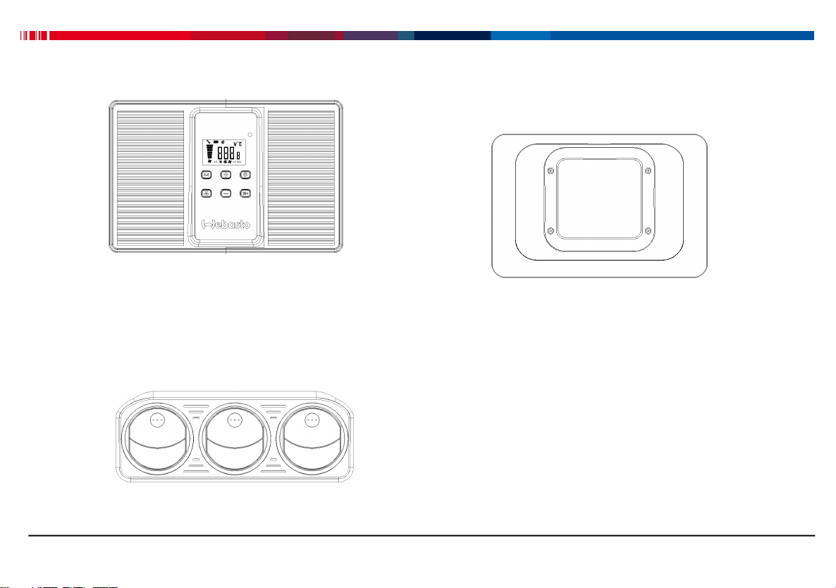
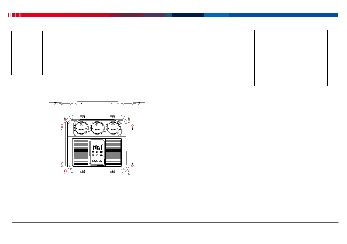
Control panel legend:
①On-Off button: Press this button to switch the Cool
Top 23 RT-E On or Off;
②Mode button: Push this button to switch among the
modes Auto, Eco, and Power.
③Airflow button: Each push on this button
corresponds to cycle through 5 different airflow levels;
④Auto 26 ℃:Press this button enables automatic
management towards 26℃;
⑤Temperature “+”button: Each pushing on this button
corresponds to the increase of 1℃of temperature;
⑥Temperature “-” button: Each pushing on this button
corresponds to the decrease of 1℃of temperature;
⑦Display window: Display temperature, airflow,
Voltage, error codes and ambient temperature.
⑧Infrared signal:Acceptance of infrared signal from
remote controller by users.
Low-voltage protection function
Settings: Long press on “26 ℃” button till screen
blinking, adjust low-voltage cutoff value (default value
is 20.5V, ranging 18-23V)via Temp“+” or “-” button,
and then long press on “26℃” button again for 5s.
⑦Display
⑤Temp“+”
②Mode
③airflow
⑥Temp“-”
④Auto 26℃
⑧Infrared
①On-Of

Roof top 23 RT-E
8
Low-voltage recovery: after the low-voltage protection
of the air conditioning battery, the low-voltage
protection will be automatically removed if the
battery voltage is above or equal to 25.5V; or starting
the vehicle to charge the battery making its voltage
higher than 25.5V to remove the low-voltage
protection.
In order to ensure the using time, it is
recommended to use the battery after it is fully
charged.
3. Remote control description
Power mode is used for fast cooling;
Eco mode is used when resting or reading is
preferred;
In Power mode, the default airflow is the biggest
with manual adjustment;
In Eco mode, compressor is running in low
frequency, airflow is defaulted as smallest with
manual adjustment.
Note: When ambient is above 35℃, and cabin in
high temperature, Power mode is preferable for
fast cooling with a result of biggest airflow and best
cooling effect.
Note: Strong recommendation for power mode
less than 20minutes. Long time operation will
significantly shorten the duration of use.
When cabin temperature is below 30℃, Auto
mode is preferred.
In different modes, users can adjust the air
volume according to their needs.
Please set it according to your own needs. Above
notes are only for reference.

9
Roof top 23 RT-E
Fig.10 Remote control panel
4. General installation¬es
4.1 Fixing holes selection
Tianlong 2007/2010/2015 Model,Delong M3000、
F3000、Auman ETX、Hongyan GENLYON、C&C、Scania
R/P series and trucks in need of cutting roof.
Fig.11
Hole pattern 7 for interior plate (4xM6 nuts)
Hole pattern 8 for fixing brackets (4xM8 nuts)
Voltage query
Temp“-”
On-Off
Temp query
Airflow“-”
Auto mode
Timer
Airflow“+”
Temp“+”
Eco mode
Power model
Mode

Roof top 23 RT-E
10
Trucks with small roof opening(e.g.Dayun) using hole
pattern 6 and 7.
Fig.12
Hole pattern 7 for interior plate (4xM6 nuts)
Hole pattern 6 for interior plate (4xM8 nuts)
4.2 Fixing Nuts&Screws installation.
Step-1: Select installation holes based on trucks
models, and fix corresponding M8 or M6 nuts via
electrical screwdriver or similar tools (perpendicular to
base frame as shown below).
after installation, it can be leveled with the horizontal
plane of the bottom plate
Torque values are as follow:
M8 nut (inner&outer threads): 6±0.5N.m
M6 nut (inner&outer threads): 4±0.5N.m
Special installation for trucks refer to Appendix 2.
Part name
Quantity
Hole
Tool
Comment
M8 nut
4
8
Electrical
screwdrive
r or wrench
nuts with
inner&out
er threads
M6 nut
4
7
Part name
Quantity
Hole
Tool
Comment
M8x90 screw
4
8
Torque
wrench
M8x90
whole
tooth
screw
M8 flange nut
M6x110 stud bolt
4
7

11
Roof top 23 RT-E
Fig.13 Installation holes schematic
Step-2: Manually fix M8x90 screws into
corresponding thread holes in first step to end, then
fix them with M8 flange nuts by wrench. And then fix
M6x110 screws in same way. Installations schematic
are shown in below.
Torque value for M8 flange nut: 10±0.5N.m
Fig.14 Screws Installation schematic
4.3 A/C main assembly installation
Step-1: Dismantle existing roof,clean the roof
perimeter zone and remove dirt with towel, ensuring
that sealing zone is dry and dustless.
Note: if there is no sunroof, the minimum opening
size is about 500mm (left and right) x400mm(front
and back)
90°

Roof top 23 RT-E
12
Fig.15 Clean roof perimeter zone
Step-2: Paste roof sealing sponge and glue at outside
and upside of foam. Details refers to section 4.4.
Fig.16 Roof foam pasting and gluing
Step-3: Place A/C in center of roof opening (avoid any
damages during installation).
Fig.17 A/C locating in center of roof opening
Step-4: Fix A/C main assembly based on truck
models. Special installation refers to section 9.3.
Fig.18 Fixing A/C main assembly

13
Roof top 23 RT-E
Step-5: Fix brackets with four flat&spring washers and
four M8 flange nuts via electrical screwdriver or other
tools. Torque for M8 nut is 8±0.5N.m. Spring washer size
is Φ30xΦ10.5x1.5.
It ranges from 6 to 10mm for sponge thickness
before and after compression.
Ensure brackets are fixed securely. Any interferences
with roof, referring to section 4.7.
Check if there is any interference for interior plate
before next step. If any, referring to section 4.6.
Fig.19 Fixing brackets
Step-6: Fix interior plate by means of four M6 nuts
with torque value of 0.8±0.5N.m
Fig.20 Fixing interior plate
Step-7: Fix power harness in below way.
Connect the power harness shown in Fig.21 via cable
bearers in accessories and avoid any damages.
During wiring layout, power harness in A/C section
fixing in truck body while the other section fixing in
battery, avoiding any possible damages to harness.
In case of cab rotation, disconnect the power
harness in advance.
Step-8: Connect negative and positive power harness
to the batteries correctly and start A/C.

Roof top 23 RT-E
14
Connector
Black negative
Fuse 60A
Battery
Red positive
Fig.21 Harness connection schematic
Note:
(1) Connect red harness end to battery positive end,
and connect black harness to battery negative end
instead of ground electrode (GND) on truck frame.
(2) Disconnecting power harness to engine starter
In order to avoid overload voltage.
(3) Paste the sealing foam firmly in order to avoid any
water leakage into cab (referring to section 4.4).
4.4 Roof hatch sealing operation
Fig.22 Roof sponge cutting notes
Roof sealing sponge installation and notes:
(1) After confirming that the sponge can completely
cover the edge of the sunroof, use the art knife (lb50h)
as shown in the figure to cut the sealing sponge
obliquely, stagger obliquely by 1cm, and squeeze and
paste it; according to the actual installation, one side or
both sides can be selected to cut obliquely, and the
cutting edge is required to be neat.
Sunroof outer edge
Shear bevel
Sunroof sealing sponge
Sponge cushion
Oblique cutting
staggered 1cm

15
Roof top 23 RT-E
Cut line
(2) Remove the oil and dust from the outside of the
sunroof, tear off the sealing sponge adhesive layer, and
paste the sealing sponge on the side of the sunroof as
shown in the figure. It is required to paste it neatly, press
it flat and tightly without warping and deformation.
(3) Apply waterproof sealant on the outside of sunroof
sealing sponge(according to the actual situation of the
vehicle, the upper part of the sponge should also be
filled with sealant if necessary),At the same time, the
cutting opening is also filled with sealant.
(4) As shown in the figure, install the sponge cushion
pad and press it to the bottom of the sealing sponge.
4.5 Universal interior plate cutting¬es
Fig.23 Interior plate cutting schematic
Interior plate cutting note:
(1) Please select the cutting size according to the
sunroof size and the actual installation situation.
(2) Use lb50h or electrical grinder with cemented
carbide saw blade to cut along the cutting line (groove
position) of interior plate. The cutting edge should be
neat and free of burr.
4.6 Fixing screws cutting¬es
Installation of M6x110 stud bolt cutting and precautions:
(1) The M6x110 stud bolt is used to fix the interior plate.
When installing, please install the 20 mm long end of the
screw tooth into the M6 inner and outer nut, and fix the
interior plate 40 mm at the other end. The cutting size
shall be selected according to the actual loading
situation.
(2) Please use an grinder for cutting, and deburring the
chamfer on the cutting end.

Roof top 23 RT-E
16
Fig.24 Stud screws cutting schematic
M8x90 screws cutting and notes:
The M8x90 full tooth bolt is used to fix the bracket.
When installing the bracket, measure the length first,
and select the cutting length according to the actual
installation situation.
4.7 Fixing brackets cutting¬es
(1) It is necessary to confirm the installation size before
cutting. If the size is too small after cutting, it will not be
able to install and fix.
(2) The grinder is used for cutting from both sides, and
the chamfering and deburring of the cutting end are
carried out.
Part
Name
Screw
tooth
length
Installation
position
Tool
Comment
M8*90
Screw
90
M8 nut
grin
der
The cutting
length should be
selected
according to the
actual situation;
the m6x110 stud
should be cut
within the thread
length of 40
M6*110
stud bolt
20
M6 nut
40
Fixed
universal
interior plate
M8x90 full tooth bolt cutting
Cutting of M6x110 stud
Chamfer cutting end
Cutting

17
Roof top 23 RT-E
Fig.25 Fixing brackets cutting schematic
5. Error codes and troubleshooting
Failure analysis of no cooling or poor effect:
(1) The power cord connected is too long and too thin,
Poor connection at connector.
(2) No refrigerant or insufficient refrigerant.
(3) Eco mode is used when the temperature is too high.
(4) Compressor or condensing fan does not work.
(5) The evaporator or condenser is dirty or blocked.
Common fault code processing method:
1: The battery power is insufficient and under voltage
E2;
(1) Check the battery for aging and replace it.
(2) If the battery is not fully charged, it needs to be
charged.
(3) Connect the negative pole of the power line to the
metal or the generator, reconnect the wirings or
harness.
2: Pressure fault (system leakage)E4;
——Refrigerant leakage or poor heat dissipation.
3: Sensor fault E0 or E1;
(1) Check whether the plug-in is loose and re-insert it
tightly.
(2) Sensor quality problem, replace the sensor.
4: High current protection F6, electronic fan fault
F7/F8;
(1) Check the condenser heat dissipation, whether the
surface is dirty and blocked.
(2) Check whether the terminal or plug-in of the power
line is loose.
(3) Check if the plug-in of the fan is loose, and plug it in
again.
(4) Condenser fan failure,replace the fan.

Roof top 23 RT-E
18
4
Ways to deal with the above code: turn off the power and turn on the machine in 5 minutes. If the fault is not
solved, please refer to the maintenance manual or contact the local dealer.
Code
Description
Troubleshooting
E0
Inlet temp sensor fault
Check sensor connector
E1
Outlet temp sensor fault
Check sensor connector
E2
Low voltage
Check battery or harness
E3
High voltage
Check battery or power
E4
Pressure(system leakage)
Check R134a leakage
F0
Disconnected/Blocked compressor
Check cooling fan working or not/ R134a overcharge
F1
Compressor driver overheat
Check cooling fan working or not/ ambient>55℃
F2
Compressor driver wire low-voltage
Check harness false connection or not
F3
Compressor driver overvoltage
Check wire false connection
F4
Compressor driver phase absence
Check wire false connection
F5
Driver output overload
Check wire false connection
F6
Driver output overcurrent
Check cooling fan working or not/ ambient>55℃
F7
Cooling fan 1 fault
Check cooling fan1 working
F8
Cooling fan 2 fault
Check cooling fan2 working

Roof top 23 RT-E
19
4
6. Maintenance
In order to ensure the normal operation of the air
conditioner, please pay attention to the routine
maintenance:
(1) When idle for a long time,please remove the
positive and negative power lines at the battery end,
and pay attention to the sealing and to avoid negative
connection direct to ground, so as to avoid battery
damage caused by long-term electrification (the
power line must be connected to the battery, and it is
strictly forbidden to connect negative direct to ground
or connect the generator).
(2) The air conditioner needs to be maintained every 3
months (cleaning evaporator and condenser, checking
internal and external circuits); the maintenance cycle
should be shortened appropriately in special working
environment, such as dusty and high temperature
environment. Refer to table 7 of the maintenance
manual for product maintenance.
(3) It is not recommended to install generators, solar
energy and other external charging equipment.
7. Disclaimer
(1) We provide installation video and installation
instructions, users must install strictly in accordance
with the video and instructions. If the user fails to install
in accordance with the installation video and instructions
provided, human failure or damage and other accidents
occur, the user shall bear the responsibility, the
maintenance and material costs caused by the user
shall be paid separately, and our company will not bear
any responsibility.
(2) The user must pay attention to safety issues
during the installation process, in case of personal
safety issues occur, the user must bear the
responsibility.
(3) If the user changes the air conditioning privately, or
the replacement of parts and components that are not
the original happens, the user shall bear the
responsibility of the caused damage to the
air-conditioning equipment and personal safety issues,
our company will not bear any responsibility.

Roof top 23 RT-E
20
4
8. Appendix 1 Accessories
Fig.26 Cool Top 23 RT-E accessories
No.
Part Names
Quantity
yies
1
M8 inner and outer tooth nut
6
2
M6 inner and outer tooth nut
4
3
M8 hexagonal flange nut
6
4
M8x90 full-tooth screw
4
5
M8x60 full-tooth screw
6
6
Φ30xΦ10.5x1.5 flat washer
6
7
M8 standard spring washer
6
8
M8 non-metallic flange locking nut
6
9
Air conditioner fixing bracket
2
10
Universal interior plate
1
11
M6 x 110 two heads screw
4
12
M6 galvanized nut
4
13
Remote control
1
14
Sponge damping pad
8
15
Cable bearer seat
10
16
Battery power cord assembly
1
17
S2 hexagonal batch heads
1
18
Cable bearer 4x150
10
19
Cable bearer 8x200
10
20
Roof hatch sealing sponge
1
Note:installation manual and labels included in accessories.
Table of contents
Other Webasto Accessories manuals