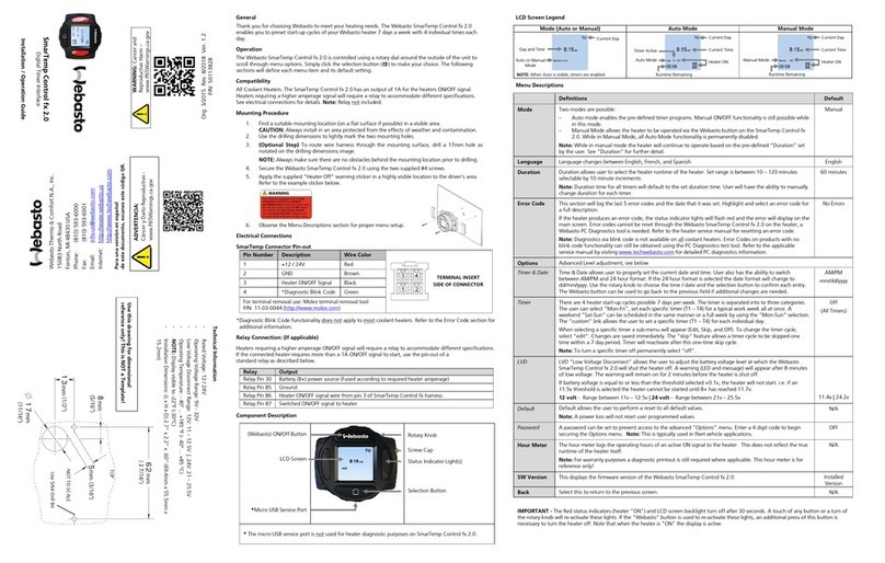
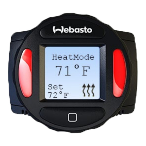
Webasto MultiControl User manual

Installation Instructions
Control element
MultiControl | SmartControl | UniBox
English
MultiControl
+HDWLQJ
+HDWLQJ
SmartControl

MultiControl | SmartControl | UniBox 2
Table of Contents
1 About This Document 3
1.1 Purpose of the document 3
1.2 Documents supplied 3
1.3 Use of this document 3
1.4 Use of symbols and highlighting 3
1.5 Liability waiver 3
2 Safety 4
2.1 Intended use 4
2.2 Qualification of the installation personnel 4
2.3 Regulations and statutory provisions 4
2.4 Safety instructions 4
3 Device Description 5
3.1 Delivery scope 5
3.2 Identification plate 5
3.3 Description of Functions 5
3.4 Device versions 5
3.5 Use 5
4 Installation of the Control Element 6
4.1 Recommendations for installation 6
4.2 Requirements for the installation location 6
4.3 Install control element 6
4.4 Optional: Install UniBox 7
5 Initial Start-up 9
5.1 Recommendations for initial start-up 9
5.2 Put the device into operation 9
5.3 Select heater 9
6 Technician Mode 11
6.1 Description of Functions 11
6.2 Connection of the diagnostic adapter 11
6.3 Select the Service menu 11
7 Fault Remedy 12
7.1 Error code 12
8 Technical Data 14
9 Annex 15
9.1 Connections 15
9.2 Technician Mode 16
9.3 Schematic Overview of Service Menu 19

MultiControl | SmartControl | UniBox 3
1 About This Document
1.1 Purpose of the document
The installation instructions form part of the device and contain
information for the correct and safe installation.
1.2 Documents supplied
All documents can be found on the enclosed DVD and can also be
downloaded from http://dealers.webasto.com.
The following documents are supplied with the device in printed
form:
■Quick-start guide
1.3 Use of this document
If necessary, print out these installation instructions.
Read these installation instructions before installing the device.
Read the instruction manual before operating the device.
1.4 Use of symbols and highlighting
WARNING
Type and source of danger
Effect: Failure to follow the instructions can lead to
serious or even fatal injuries
Action to protect yourself from the danger.
CAUTION!
Type and source of danger
Effect: Failure to follow the instructions can lead to
minor injuries
Action to protect yourself from the danger.
CAUTION
Type and source of material damage
Effect: Failure to follow the instructions can lead to
material damage
Action to avoid material damage.
Further information can be found in the following
documents:
■...
■...
Reference to a special technical feature.
Highlighting Explanation
3Precondition for the subsequent instruction
Instruction
1.5 Liability waiver
Webasto assumes no liability for faults and damage resulting from
a failure to follow the installation instructions and instruction
manual and the tips contained therein.
This liability waiver applies in particular to:
■Installation by unqualified personnel
■Improper use
■Repairs not carried out by a Webasto service workshop
■Use of non-original parts
■Modification of the device without the approval of Webasto
https://webasto-russia.ru

MultiControl | SmartControl | UniBox 4
2 Safety
2.1 Intended use
The control element serves to control the heater.
2.2 Qualification of the installation per-
sonnel
The installation personnel must have the following qualifications:
■Successful completion of the Webasto training
■Corresponding qualification for working on technical systems
2.3 Regulations and statutory
provisions
Observe the important information in the "Quick-start guide"
leaflet.
2.4 Safety instructions
Safety instructions for installation
Hazard of electric shock from live components
Before installation, disconnect the vehicle from the power sup-
ply.
Pay attention to proper earthing of the electrical system.
Observe the legal provisions.
Observe the information on the identification plate.
Danger of cuts from sharp edges
Fit chafers to sharp edges.
Safety instructions for operation
Risk of explosion in areas with flammable vapours, flammable
dusts and
hazardous goods (e.g. petrol stations, tank installations, fuel
stores, coal stores, wood stores or grain stores)
Do not switch on or operate the heater.
Risk of poisoning and suffocation caused by exhaust fumes in
enclosed areas without exhaust extraction system
Do not switch on or operate the heater.
Avoid material damage
Risk of short-circuit resulting from damage to cables due to sharp
edges
Fit chafers to sharp edges.

MultiControl | SmartControl | UniBox 5
3 Device Description
3.1 Delivery scope
■MultiControl / SmartControl
■Double-sided adhesive pad
■Optional: Holder for MultiControl / SmartControl
■Optional: UniBox
■Optional: Holder for UniBox
3.2 Identification plate
The identification plate is located on the rear side of the control
element.
3.3 Description of Functions
Control element
The MultiControl and SmartControl control elements are used to
control Webasto heaters.
The additional installation of the UniBox (optional) may be neces-
sary, depending on the installed heater and the application.
Heating
Fig. 01: MultiControl / SmartControl control elements
1 Submenu designation
2 Submenu symbol
3 Activated time setting
4 Time
5 Quick-start button
6 Control knob
UniBox
The UniBox allows heaters not compatible with the W bus to
also be operated with the MultiControl and SmartControl control
elements. Furthermore, the UniBox provides further inputs and
outputs which extend the scope of functions.
Communication between UniBox and control element is via the
W bus. The UniBox is automatically configured after selecting the
heater at the control element.
The UniBox is installed in an area of the vehicle not visible to the
customer.
3.4 Device versions
The control element is available in two versions:
■SmartControl: Control element with black frame without timer
function.
■MultiControl: Control element with silver frame and with timer
function.
The heaters and default settings supported depend
on the version of the control element used.
3.5 Use
The heaters for which the control element may be used can be
found under: http://dealers.webasto.com

MultiControl | SmartControl | UniBox 6
4 Installation of the Control Element
4.1 Recommendations for installation
CAUTION!
Electric shock if live parts are touched
Minor burns
Isolate the vehicle before installation (vehicle
initialisation may be lost).
CAUTION!
Risk of fire due to incorrect installation
Risk of burns
Observe the additional regulations if installing the
heater in vehicles for hazardous goods transport.
Observe the information on the identification
plate.
CAUTION!
Risk of fire caused by drilling into lines or
cables
Risk of burns
Lay lines and cables behind the installation sur-
face out of the drilling area.
CAUTION!
Risk of injuries caused by touching sharp
edges
Skin abrasions, cuts
Use protective gloves during installation.
4.2 Requirements for the installation loca-
tion
The installation location must satisfy the following requirements:
3Vehicle interior
3Easily accessible
3Clear visibility
3Clean, dry and grease-free
3Protected from dampness and moisture
3Protected from heat, not directly in the hot air current
3Adequate free space behind the installation location
4.3 Install control element
Installation with adhesive pads
123
Fig. 02: Install control element with adhesive pads
1 Installation location
2 Adhesive pads (adhesive on both sides)
3 Control element
Determine the installation location.
When determining the location, pay attention to
the length of the control element cable.
Determine the location for the leadthrough of the control ele-
ment wiring harness.
Lay the control element wiring harness through from the front.
3The rear side of the control element is clean, dry and free from
dust or grease.
Attach the adhesive pads to the control element.
Attach the control element to the selected installation location.

MultiControl | SmartControl | UniBox 7
Optional installation with holder
12 43
Fig. 03: Install control element with holder
1 Installation location
2 Holder
3 Screws
4 Control element
Determine the installation location.
Determine the location for the leadthrough of the control ele-
ment wiring harness.
Install the holder using the screws supplied.
Lay the control element wiring harness through from the front.
Clip the control element into the holder.
Observe the statutory regulations when installing
in cars.
1
2
Fig. 04: Connection example control element (1) with heater (2)
4.4 Optional: Install UniBox
Fig. 05: Optional: Install UniBox with holder
Determine the installation location.
Install the device in an area of the vehicle not visible
to the customer.
Install the holder using the screws supplied.
Determine the routing of the wiring harness of the UniBox.
Clip the UniBox into the holder.

MultiControl | SmartControl | UniBox 8
12
3 4
Fig. 06: Connection example – UniBox (1), control element (2), heater (3)
and vehicle wiring harness (4)

MultiControl | SmartControl | UniBox 9
5 Initial Start-up
5.1 Recommendations for initial start-up
WARNING
Inhalation of toxic gases in enclosed areas
Risk of poisoning and suffocation
Never use the heater in enclosed areas such as
garages or workshops without exhaust extraction
system, even in the case of programmed heating.
In workshops with exhaust extraction system,
ensure that the exhaust extraction system is
functioning.
5.2 Put the device into operation
3Heater is correctly installed.
3Control element is correctly installed.
Connect the vehicle power supply.
5.3 Select heater
For initial start-up
When the control element is connected for the first
time, a message about the missing setting/configu-
ration of the heater is displayed.
Fig. 07: Symbol "Missing configuration"
Press the control knob and the quick-start knob simultaneously
for 3 seconds.
+HDWHU
Fig. 08: Menu element "Heater"
Select the desired heater.
Press the control knob.
'D\
Fig. 09: Menu element "Day"
Select the current day.
Press the control knob.
Fig. 10: Menu element "Time"
Select the current time.
For manual reset
A reset returns all the settings and timer pro-
grammes in the control element to the basic set-
tings or to the default values set by the technician.
At a reset, the language setting is reset to English.
In the main menu, select the symbol "Settings" .
Settings
Fig. 11: Menu element "Settings"
Press the control knob.
Select menu element "Reset".
Reset
Settings
Fig. 12: Menu element "Reset"
Press the control knob.
Reset
Settings
Fig. 13: Menu element "Confirm reset"
To confirm the menu selection, press the control knob again.
3The control element is restarted.
During the restart of the control element (the starting mask is
displayed for 1.5 seconds), press the control knob and quick-
start knob simultaneously for 3 seconds.

MultiControl | SmartControl | UniBox 10
+HDWHU
Fig. 14: Menu element "Heater"
Select the desired heater.
Press the control knob.
The correct selection for the corresponding heater
can be found in the workshop manual for the
heater.

MultiControl | SmartControl | UniBox 11
6 Technician Mode
6.1 Description of Functions
This special function is not visible for the customer and is only
enabled when the diagnostic adapter is connected. With this
function, the preset heaters with their settings can be selected
and activated. The limit values for temperature/operating time,
etc., can be altered by the technician in the event that they have
not been correctly preset for the installed system. Alternatively the
settings can also be altered using the WTT (Webasto Thermo Test)
diagnostic software.
Factory settings may only be changed by qualified
personnel.
6.2 Connection of the diagnostic adapter
Remove the cover of the diagnostic adapter port.
Fig. 15: Removal of the cover
CAUTION
Dust and moisture can damage the diagnostic
adapter port
The device can then make incorrect or no diagnoses
Fit the cover of the diagnostic adapter port again
after use.
Connect the diagnostic adapter to the control element.
Fig. 16: Connection of the diagnostic adapter
6.3 Select the Service menu
In the main menu, select the symbol "Service" .
6HUYLFH
Fig. 17: Menu element "Service"
The menu items of the technician menu are an
extension of the operator menu and are addition-
ally available. The "Service" symbol replaces the
"Settings" symbol as soon as the diagnostic adapter
is connected.
Further information can be found in the Annex:
„Technician Mode“.

MultiControl | SmartControl | UniBox 12
7 Fault Remedy
7.1 Error code
If a fault occurs in the heater during heating, the
heater outputs an error code via the control ele-
ment.
Further information can be found in the instruction
manual of the heater.
Internal control element error table "Txx"
A fault is signalled as Txx or as Fxx on the display of
the control element together with the red flashing
LED. The fault display also appears after waking up
the control element from standby mode and must
be acknowledged by pressing the control knob or
the quick-start knob. This fault is stored in the error
codes in the menu (menu element "Error code") of
the control element and can be called up. With a
"Reset" via the customer menu, all error codes in
the control element and the UniBox are deleted.
Error code Fault Fault description Fault remedy
Ted Overvoltage Supply voltage is above 36V. Check vehicle electrical installation.
Te3 Display background lighting defective Contact Technical Support/Customer Service.
Te4 Status LED defective Contact Technical Support/Customer Service.
Te5 Temperature sensor fault Temperature sensor of the MultiControl/SmartCon-
trol defective. Contact Technical Support/Customer Service.
Te6 W bus temperature sensor fault Temperature from the external sensor (W bus) can-
not be read correctly. Check installation. Replace the sensor, if necessary.
T5d UniBox temperature sensor fault Temperature from the external sensor connected to
the UniBox cannot be read correctly. Check installation. Replace the sensor, if necessary.
T12 Communication fault on the W bus Check installation.
Te7/Te8 Flash Reading/writing from/to the internal memory has
failed. Contact Technical Support/Customer Service.
Tea Faulty feedback signal from the heater (ST) Check installation.
Tec Jamming control knob A control knob is pressed for longer than 10
seconds. Contact Technical Support/Customer Service.
T46 Overcurrent/short-circuit at switching output SAU1 Current is higher than 500mA.
Check installation. Ensure that the consumer at
switching output SAU1 does not draw a higher
current than 500mA.
T49 Overcurrent/short-circuit at switching output SAU2 Current is higher than 20mA. Check installation. Ensure that this switching output
is only connected to the corresponding heater.
Te0 Reduced voltage Supply voltage is below the value set by the techni-
cian.
Recharge the battery and check the vehicle's electri-
cal installation
T84 Low voltage Supply voltage is below 8V. Recharge the battery and check the vehicle's electri-
cal installation
Te1 Ambient temperature too low/high Ambient temperature is outside the working range
of -20°C to +70°C.
The fault disappears automatically when the ambi-
ent temperature returns to the working range of
-20°C to +70°C.
Teb RTC error The internal clock chip of the MultiControl/Smart-
Control has lost its setting.
In the event of interruptions in the power supply
of more than 8 minutes: Enter the date and time
again.
If the error occurs without an interruption in the
power supply: Contact Technical Support/Customer
Service.
Tee
Defective switching transistor in the MultiControl/
SmartControl Contact Technical Support/Customer Service.
Attention: If this fault occurs, the heater can no longer be switched off. Please remove the fuse immediately and drive to a workshop.

MultiControl | SmartControl | UniBox 13
Fault in connected UniBox with analogue heater
Error code Fault Fault description Fault remedy
Fed Overvoltage Supply voltage is above 36V. Check vehicle electrical installation.
F5d Temperature sensor fault Temperature from the external sensor connected to
the UniBox cannot be read correctly.
Check installation. Contact Technical Support/Cus-
tomer Service.
F12 Communication fault on the W bus Check installation.
Fe7/Fe8 Flash Reading/writing from/to the internal memory has
failed. Contact Technical Support/Customer Service.
Fe9 Implausible signal from switching output SAU1 The UniBox receives an implausible
signal.
Check installation. Contact Technical Support/Cus-
tomer Service.
Fea Faulty feedback signal from the heater (ST) Check installation.
Fec Jamming external control knob The external control knob is pressed for longer than
10 seconds.
Check installation. Contact Technical Support/Cus-
tomer Service.
F01 to F0F Heater fault Please refer to the documentation on the heater. Contact Technical Support/Customer Service.
T84 Low voltage Supply voltage is below 8V. Recharge the battery and check the vehicle's electri-
cal installation
Fault in a connected W bus heater
Error code Fault Fault description Fault remedy
F01 to FFE Heater fault Please refer to the documentation on the heater. Contact Technical Support/Customer Service.

MultiControl | SmartControl | UniBox 14
8 Technical Data
Control element MultiControl / SmartControl UniBox
Nominal voltage [V] 12 to 24
Maximum power consumption (during
operation without external relay) [mA] 17 to 23 12
Maximum power consumption (in standby)
[mA] 0.5
Admissible ambient temperatures [°C]
(operation / storage) -40 to +75 / -40 to +90
Dimensions of control element [mm]
(length / depth / height) 68 / 15 (9.5 without control knob) / 48 90 (104 with connected wiring harness) / 60 / 25
Weight [g] 41 66

MultiControl | SmartControl | UniBox 15
9 Annex
9.1 Connections
Legend – Control element connections
Item Col-
ours
Name Remarks
Contact 1 yellow W bus / low switch /
diagnosis
The connection is configured
differently, depending on
the choice of heater. Please
note that heaters with
analogue control do not
have a W bus available on
this lead. A W bus diagnosis
is only possible with con-
nected W bus heater or with
connected UniBox.
Contact 2 black Switching output SAU1 max. switching current
500 mA
Contact 3 red KL30 Plus+
Contact 4 brown KL31 Earth-
4
3
2
11
Fig. 18: Control element connections
Legend – UniBox connections
Item Col-
ours
Name Remarks
Contact 1 red KL30 Plus+ (control element)
Contact 2 brown KL31 Earth- (control element)
Contact 3 yellow W bus W Bus (control element)
Contact 4 grey Switching output SAU1 Switching output heating
(operating element)
Contact 5 red KL30 Plus+
Contact 6 brown KL31 Earth-
Contact 7 green /
white W bus W bus
Contact 8 black Switching output SAU1 Switching output heating
(high side) from the UniBox
Contact 9 red /
white Switching output SAU2
Switching output ventilation
(low side) from the UniBox
max. switching current
20 mA
Contact 10 TS (Plus) External room temperature
sensor
Contact 11 TS (earth) External room temperature
sensor
Contact 12 blue SWG (Plus) Setpoint input
Contact 13 white SWG (earth) Setpoint input
Contact 14 black /
grey KL15 Ignition
Contact 15 violet ADR (TRS) ADR mode
Display on control element
Contact 16 green SEI
Switching input
External button for switch-
ing ON/OFF
Contact 17 red /
black ST / Status Error code / status
Item Col-
ours
Name Remarks
Contact 18 white /
red Multifunction Multifunction input (air
heater)
9
18
1
10
1
Fig. 19: UniBox connections

MultiControl | SmartControl | UniBox 16
9.2 Technician Mode
Service settings
This special function is not visible for the user and is only enabled
when the diagnostic adapter is connected. With this function, the
preset heaters with their settings can be selected and activated.
The limit values for temperature/heating time, etc., can be altered
by the technician in the event that they have not been correctly
preset for the installed system. Alternatively the settings can also
be altered using the WTT without diagnostic cable.
Factory settings may only be changed by qualified
personnel.
3Connect the plug of the diagnostic cable to the control element.
3Select the "Service" symbol in the main menu.
Press the control knob.
3The "Quick-start" symbol appears on the display.
Select heater
This menu item allows a different heater to be selected. When a
different heater is selected, other settings from this menu are also
reset to the specific values for the heater. The error memory is also
deleted.
3Select the "Service" symbol in the main menu.
3The "Quick-start" symbol appears on the display.
Turn the control knob to select the desired symbol "Heater".
3The name of the heater appears on the display.
Turn the control knob to select the heater.
Press the control knob to confirm the selection.
Min duration
Default setting of the minimum operating time that the customer
can select during configuration of the quick-start button or from
the menu during heating/ventilation. The value for "Min duration"
can be set between 10 minutes and the "Max duration".
3Select the "Service" symbol in the main menu.
3The "Quick-start" symbol appears on the display.
Turn the control knob to select the desired symbol "Min dura-
tion".
Press the control knob to confirm the selection.
3The "Min duration" appears on the display and the "hour" digit
flashes.
Turn the control knob to select the desired "hours" for the "Min
duration".
Press the control knob to confirm the selection.
3The "Min duration" appears on the display and the "minute"
digit flashes.
Turn the control knob to select the desired "minutes" for the
"Min duration".
Press the control knob to confirm the selection.
Max duration
Default setting of the maximum operating time that the customer
can select during configuration of the quick-start button or from
the menu during heating/ventilation. The value for "Max duration"
can be set between the value for "Min duration" and the maxi-
mum time permissible for the selected heater.
3Select the "Service" symbol in the main menu.
3The "Quick-start" symbol appears on the display.
Turn the control knob to select the desired symbol "Max dura-
tion".
Press the control knob to confirm the selection.
3The "Max duration" appears on the display and the "hour" digit
flashes.
Turn the control knob to select the desired "hours" for the "Max
duration".
Press the control knob to confirm the selection.
3The "Max duration" appears on the display and the "minute"
digit flashes.
Turn the control knob to select the desired "minutes" for the
"Max duration".
Press the control knob to confirm the selection.
Permanent mode
This allows continuous operation of the heater to be enabled or
barred for the user. Permanent mode is only possible with heaters
which support this mode. If this option is selected for heaters
which do not support permanent mode, the heater dictates the
operating time when the user starts the heating/ventilation func-
tion in permanent mode.
3Select the "Service" symbol in the main menu.
3The "Quick-start" symbol appears on the display.
Turn the control knob to select the desired symbol "Permanent
mode".
Press the control knob to switch between "On" and "Off".
This setting is saved without confirmation.

MultiControl | SmartControl | UniBox 17
Ventilation
This option allows the menu item "Ventilation" to be removed
from the customer menu. This option has no influence on heaters
that do not support "Ventilation".
3Select the "Service" symbol in the main menu.
3The "Quick-start" symbol appears on the display.
Turn the control knob to select the desired symbol "Ventilation".
Press the control knob to switch between "On" and "Off".
This setting is saved without confirmation.
Temperature range
This option allows the temperature range for air heaters to be
limited that the user can during configuration of the quick-start
button or from the menu during heating. The minimum tempera-
ture can be selected between 5°C and 20°C and the maximum
temperature between 20°C and 35°C. This setting has no influ-
ence on water heaters.
3Select the "Service" symbol in the main menu.
3The "Quick-start" symbol appears on the display.
Turn the control knob to select the desired symbol "Temperature
range".
3If the temperature setting function is not supported by the
heater, "N/A" appears on the display and no settings can be
made here.
Press the control knob to confirm the selection.
3The minimum temperature appears on the display.
Turn the control knob to select the desired minimum tempera-
ture.
Press the control knob to confirm the selection.
3The maximum temperature appears on the display.
Turn the control knob to select the desired maximum tempera-
ture.
Press the control knob to confirm the selection.
Show temperature
This option allows the temperature display in the status line to be
configured. If this option is deactivated, no actual temperature is
displayed in the status line. The displayed temperature is always
the actual temperature signalled by a connected sensor or the
internal sensor of the MultiControl/SmartControl. After a factory
reset or when a new heater is selected, all possible sensors are
scanned and the first available sensor for the temperature meas-
urement is selected. The scanning sequence is:
■External sensor on the W bus
■Sensor in the heater
■External sensor connected to the UniBox
■Internal sensor of the MultiControl/SmartControl
3The temperature can be displayed and hidden in the main
menu.
3Select the "Service" symbol in the main menu.
3The "Quick-start" symbol appears on the display.
Turn the control knob to select the desired symbol "Display
temperature".
Press the control knob to switch between "On" and "Off".
This setting is saved without confirmation.
UniBox
After a factory reset or when a new heater is selected, a scan for
detection of a possibly UniBox is always performed automatically.
If the UniBox is retrofitted, the support can be forced by activat-
ing this option and hence the additional functions, e.g. ignition
detection, ADR, additional external button (analogue quick-start
button) can be used.
3Select the "Service" symbol in the main menu.
3The "Quick-start" symbol appears on the display.
Turn the control knob to select the desired symbol "UniBox".
Press the control knob to switch between "On" and "Off".
This setting is saved without confirmation.
Undervoltage shutdown
When the option is activated, the supply voltage is constantly
monitored during heating/ventilation and if the voltage drops
below the configured value for more than 5 seconds, the heater is
switched off. The heater can only be switched on again when the
voltage is stable and above the configured value. Undervoltage is
signalled in the status line with a battery symbol.
3Select the "Service" symbol in the main menu.
3The "Quick-start" symbol appears on the display.
Turn the control knob to select the desired symbol "Low volt-
age".
3If the undervoltage shutdown is active, the preset value is
shown on the display. If it is deactivated, "Off" is displayed.
Press the control knob to confirm the selection.
Turn the control knob to set the value or to deactivate the func-
tion (Off).
Press the control knob to confirm the selection.

MultiControl | SmartControl | UniBox 18
Max active timers
As standard, only one timer can be activated. This option allows
the number of timers that can be activated simultaneously to be
increased to 21.
Please observe the statutory regulations, in particular that only
one active timer is permitted for cars.
3Select the "Service" symbol in the main menu.
3The "Quick-start" symbol appears on the display.
Turn the control knob to select the desired symbol "Max active
timers".
3The default value (number of timers) is displayed.
Press the control knob to confirm the selection.
Turn the control knob to set the value.
Press the control knob to confirm the selection.
Basic configuration
During a reset, all settings are return to the basic configuration
with the exception of the day of the week and the time. After the
reset, the procedure is the same as after installation and for the
initial start-up.
3The "Quick-start" symbol appears on the display.
Turn the control knob to select the desired symbol "Factory
settings".
Press the control knob to confirm the selection.
3"OK" appears on the display.
3Press the control knob to confirm the selection.
3A restart is performed.

MultiControl | SmartControl | UniBox 19
9.3 Schematic Overview of Service Menu
Fig. 20: Schematic overview of service menu

Ident-Nr. 9030531A01 • 04/14 • Errors and omissions excepted • Printed in Germany • © Webasto Thermo & Comfort SE, 2014
Webasto Thermo & Comfort SE
Postfach 1410
82199 Gilching
Germany
Visiting Address:
Friedrichshafener Str. 9
82205 Gilching
Germany
The telephone number of each country can be found in the
Webasto service center leaflet or the website of the respective
Webasto representative of your country.
In multilingual versions the German language is binding.
Other manuals for MultiControl
2
This manual suits for next models
2
Table of contents
Other Webasto Control Unit manuals
Popular Control Unit manuals by other brands

Minebea
Minebea MPC-201B-25 instruction manual

turck
turck TBEN-LH-8IOL Configuration guide

SST Automation
SST Automation GS11-EI user manual

Jafar
Jafar 6516 Operation and maintenance manual

Deviser
Deviser TC701B Operation manual

UTC Fire and Security
UTC Fire and Security KiddeFire Systems ARIES NETLink BACnet user guide

Evco
Evco C-PRO 3 CLIMA sistema+ Installer manual

ICM Controls
ICM Controls ICM292 Installation

Texas Instruments
Texas Instruments BQ25181 user guide

ADLINK Technology
ADLINK Technology cPCI-6830 Series manual

Val-Matic
Val-Matic 801SSBW Operation, maintenance and installation manual

M-system
M-system R7M-RS4 instruction manual