ThermoConnect 3
1.4 Intended use
The ThermoConnect system is designed
for controlling Webasto air - and water
heaters with any compatible mobile phone
or web app. The ThermoConnect is con-
nected electrically to the air- or water
heater and gets its commands using a 2G
network connection. Commands are send
by a mobile phone with the
ThermoConnect app or a web browser
(My WebastoConnect).
For more information, please con-
tact the Webasto Service Centre.
2 Operating ThermoConnect
You can operate the air - or water heater
in 3 ways:
■With the Push button.
■With the ThermoConnect app on a
mobile phone.
■With the "My WebastoConnect" web
page.
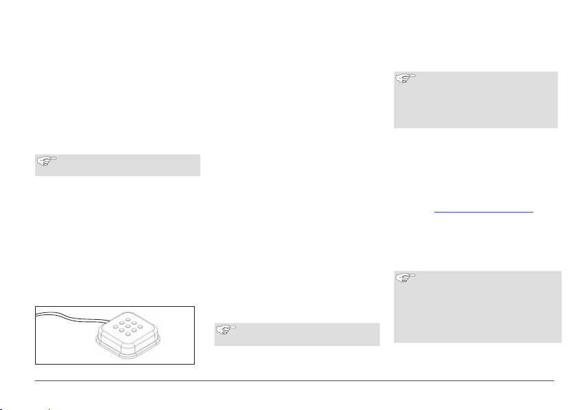
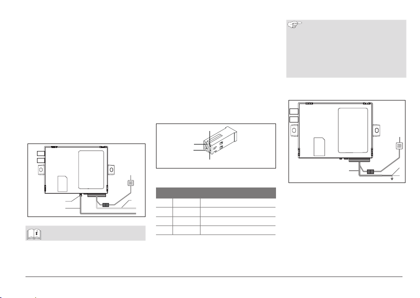
3 Push button
Fig.1 Push button
The Push button is located within the driv-
er's reach. The Push button switches the
air- or water heater on or off with a de-
fault duration (60min).
Press the Push button to start the air-
or water heater.
If necessary, the default duration can be
changed. See "5 My WebastoConnect
web service" on page 3.
The backlight of the push button is also a
status indicator:
-Off - Heater off
-Red (blinking) - The ThermoConnect
is not connected, is searching for a
network or is restarting
-Red (bright) - Heater on
Use of the Push button to restart and reset
settings of the ThermoConnect.
■Restart See 6.2.1 on page 4
■Reset See 6.2.2 on page 4
4 Mobile phone app
3Make sure that the ThermoConnect
app is installed on the mobile phone.
To install the app: See "12 Initial
start-up" on page 9.
The ThermoConnect is operated using any
network-connected compatible mobile
phone with the Webasto ThermoConnect
app.
Not all settings can be controlled
by using the app. More settings are
available in the web service.
See "5 My WebastoConnect web
service" on page 3.
5 My WebastoConnect web
service
ThermoConnect settings can be controlled
using the My WebastoConnect web ser-
vice.
Go to "my.webastoconnect.com".
Enter the temporary identification num-
ber shown in mobile app under the My
WebastoConnect item of the app or
use the ThermoConnect account cre-
dentials.
All app settings are also available in
My WebastoConnect and will be
synchronised automatically. Context-
specific help for each setting is avail-
able in My WebastoConnect service.