STAY ALERT
Do not operate the machine while under the influence of drugs, alcohol, or any medicaon that could affect
your ability to use it properly. Do not use this machine when you are red or distracted from the job at hand.
Be aware of what you are doing at all mes. Use common sense.
AVOID DANGEROUS CONDITIONS
Make sure there is adequate surrounding workspace. Cluered areas invite injuries.
Keep your work area clean with sufficient light. Keep area around the machine clear of obstrucons, stones,
scks, wires and other debris or foreign bodies which could cause damage to the machine.
DO NOT SMOKE, whilst using the machine.
INSPECT YOUR MACHINE
Check all bolts, nuts, and screws for ghtness before each use, especially those securing guards and drive
mechanisms. Vibraon during use may cause these to loosen.
Replace damaged, missing or failed parts before using.
Warning labels carry important informaon.
Replace any missing or damaged warning labels.
DRESS PROPERLY
Do not wear loose clothing, gloves, scarfs, neckes or jewelry (rings, wrist watches), which can be caught in
moving parts.
ALWAYS wear protecve eye and ear wear. Appropriate gloves are also recommended.
Wear protecve hair covering to contain long hair, prevenng it from geng caught in machinery.
DO NOT use whilst barefoot or wearing open toed footwear.
KEEP BYSTANDERS AND CHILDREN AWAY
Keep unauthorised persons or animals a minimum distance of 15 metres away from the mower. Do not allow
children to handle, use, or climb on the machine.
DO NOT OVERREACH
Keep proper foong and balance at all mes, parcularly if using on slopes. The machine should not be used
on steep slopes and always be sure of foong.
AVOID INJURY FROM UNEXPECTED ACCIDENT
Keep hands out of the way of moving parts, parcularly the engine and rotang cung tool.
DO NOT FORCE TOOL
Always work within the rated capacity. Do not use the machine for a purpose for which it was not
intended. Always use the correct handles and shoulder straps provided with the machine.
MAINTAIN YOUR MACHINE WITH CARE
Clean the machine immediately aer use. Keep the machine clean to ensure it operates to its full and safest
performance. When maintaining this machine, only the manufacturer’s original replacement parts should be
used. The use of non-original manufacturer parts may invalidate your warranty.
STORE IDLE EQUIPMENT
When not in use, the machine should be stored in a dry locaon. Keep the machine away from children and
others not qualified to use it. DO NOT STORE FUEL IN THE MACHINE, fuel over 30 days old can become stale
and if used, damage the carburetor, which is not covered by the manufacturer’s warranty.
SAFETY INSTRUCTIONS
Read and understand the owner’s manual and labels affixed to the machine. Learn its applicaon and
limitaons as well as the specific potenal hazards. Retain these instrucons for future reference. The
operator is responsible for following the warnings & instrucons in this manual and on the product.
Read & understand operator’s manual
before using the machine. Failure to
follow instrucons could result in
death or serious injury.
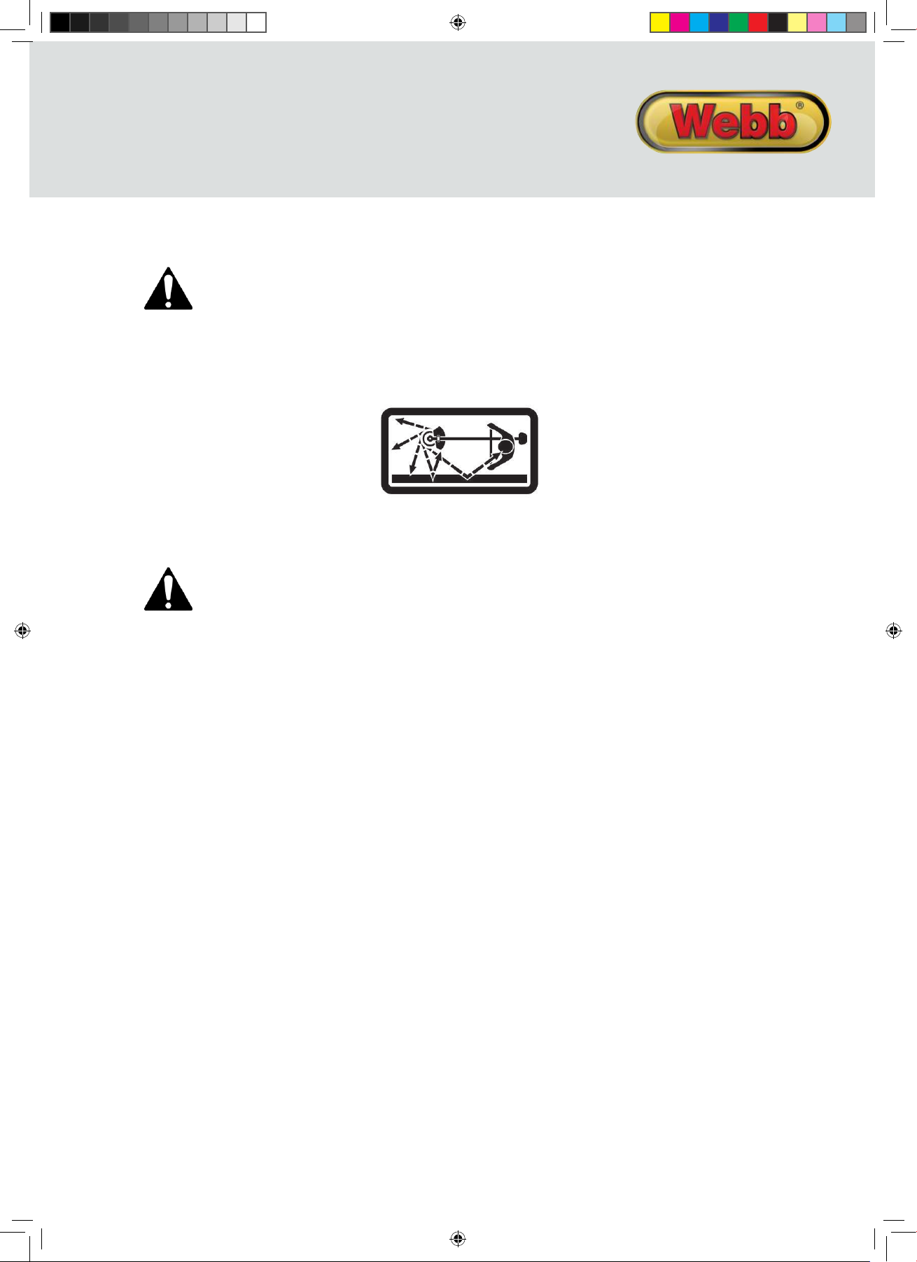
This graphic and when accompanied by
WARNING or DANGER, calls aenon
to acons which could lead to SERIOUS
INJURY
Always wear eye and ear protecon
Always TURN OFF THE ENGINE,
ensuring the cung tool has stopped,
before cleaning, removing or adjusng
the blade.
Always wear gloves to protect your
hands.
SHARP ROTATING BLADES
Wear foot proteconor sensible shoes
when using the machine
WARNING
Never modify a machine in any way.
Incorrect use of a machine can cause
SERIOUS OR FATAL PERSONAL INJURY
15m
Keep all bystanders & animals at least
15 metres away from the machine
during operaon.
If approached, stop the machine
immediately.
No smoking
Risk of Carbon Monoxide Poisoning.
Ensure working area is correctly
venlated.
Do not use near a flame, or sparks
Fire and its vapors are extremely
flammable & explosive.
Fire or explosion can cause severe
burns or death.
Rotang parts can contact or entangle
hands, feet, hair, clothing or
accessories.
Traumac amputaonor severe
laceraon can result
Running engines produce heat. Engine
parts, especially the exhaust, become
extremely hot.
Severe thermal burns can occur on
contact
Safety alert symbol. Used to alert you to potenal personal injury hazards. Obey all safety messages that
follow this symbol to avoid possible injury.
DANGER
Indicates an imminently hazardous situaon which, if not avoided, will result in serious injury.
WARNING
Indicates a potenally hazardous situaon which, if not avoided, could result in serious injury
CAUTION
Indicates a potenally hazardous situaon which, if not avoided, may result in minoror moderate injury.
CAUTION
Used without the safety alert symbol indicates a potenally hazardous situaon which, if not avoided, may
result in property damage.
INSTRUCTION MANUAL
WEPHT26 193879001 IM.indd 5 27/06/2016 13:58