SD20L / SD26L
WARNING -
safe usage instructions
1. The jacking beam is only to be mounted on lifts
approved by the lift manufacturer for mounting
of jacking beams - be aware that not all lifts are
approved. Rated beam capacity must be max.
2/3 of vehicle lift capacity.
2. Mount the jacking beam with adequate support
arms on horizontal, parallel and solid rails and
secure it against crashing before use. See para-
graph “Assembly Instructions for Support Arms”.
3. The jacking beam has been constructed for
operation only by trained personnel, having read
and understood this manual.
4. Check before each lift, that the support arms are
correctly placed on rail of lift or pit edge.
5. This is a lifting device only. Do not move or trans-
port vehicle with jacking beam.
6. Always lower the jacking beam to the nearest
safety stop immediately - or use axle stands for
support - before working on vehicle.
7. Do not overload, for instance due to sudden exter-
nal load. Overload can cause damage or failure of
jack.
8. Lift only on points as specified by automaker.
During lifting be attentive that the saddles cannot
slide.
9. When lifting the complete vehicle by means of 2
jacking beams they shall be placed minimum
0,85 m from each other.
10. Gravity of load must always be placed centrally.
When lifting by means of only one saddle always
place it in the centre of the jacking beam. Also,
the 2 extension arms must only be used simulta-
neously.
11. The wheels of the vehicle is to point forward and
be chocked.
12. No person must remain in, on or under a vehicle
when lifted or supported only by the jacking beam.
13. The operator must observe, that the jacking beam
can be operated without any danger to himself and
others.
14. The jacking beam as well as the safety valve is not
to be altered.
15. Failure to follow these warnings may result in loss
of load, damage to jack, and/or failure resulting in
personal injury or property damage.
GB
Assembly
See paragraph “Assembly Instructions for Support
Arms” on previous pages.
Use
Lifting: Pump the handle. Lower to the nearest safety
stop by turning opposite.
Lowering: Lift a little to allow release of safety stop.
Turn both handles counter clockwise
(release valve to the left, release for safety stop to the
right). Both handles automatically return to neutral.
Maintenance
Maintenance and repairs must always be carried out
by qualified personnel.
Daily: Check jacking beam and supports for damage
- and the correct placement of supports.
Monthly: Lubricate all moving parts with oil.
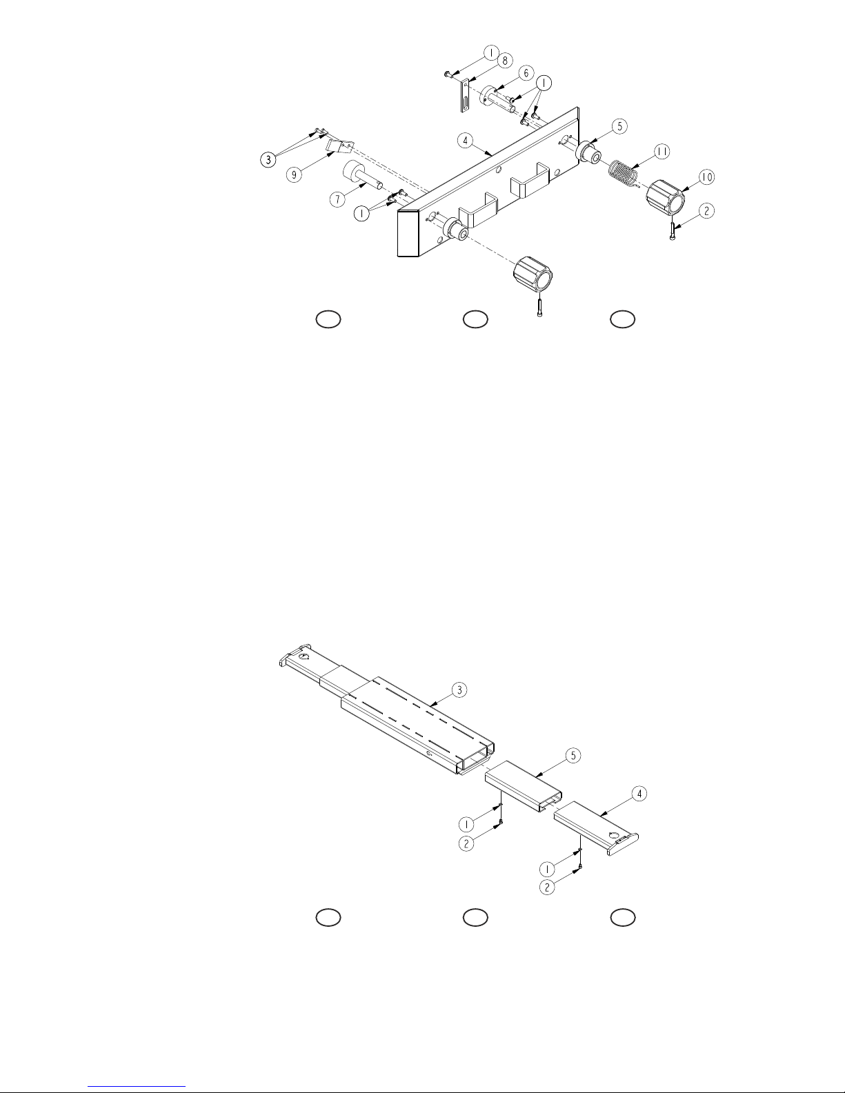
Oil refill and check: Lift to maximum height without
load and remove filler plug (11). Correct oil-level is up to
the lowest hole.
Oil quantity: 0,6 l. - Any good hydraulic oil with
viscosity ISO VG 15 can be used.
Never use brake fluid.
Safety inspection
In accordance with national regulations - yet, at least
once a year - the following parts must be checked
by an expert: Supports and support arms (security
against crashing), abnormal wear and damages,
weldings and the hydraulic system for leaks.
Possible faults and how to overcome them
1. T he jacking beam cannot lift to maximum height:
Refill the oil tank. (See “Maintenance”).
2. T he jacking beam cannot lift enough: Check that
release handle is on “neutral” and can move
freely. Both release 6222600 (adjusted with nut
0262700) and release arm 6222702 (adjusted with
counternuts 2 x 0201600 on the pump’s release
spindle) must be loose to allow the release valve to
close tightly.
3. T he jacking beam cannot lower to minimum
position: Check for damages; lubricate mechanical
parts.
4. T he jacking beam continues to lower after letting
go of the release handle: Ventilate the hydraulic
cylinder by screw (10).
Warning: The jacking beam is not to be loaded.
Destruction
The oil must be drained off and legally disposed of.