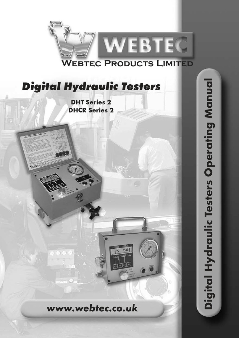
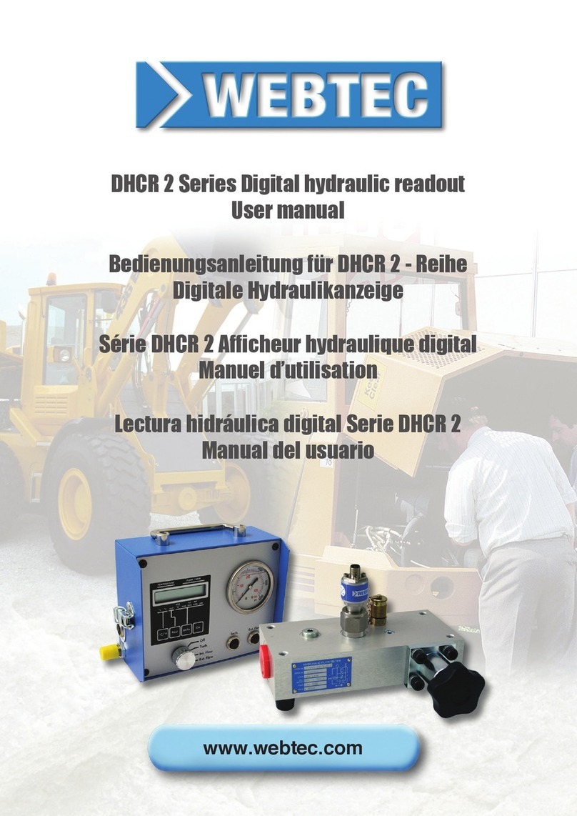
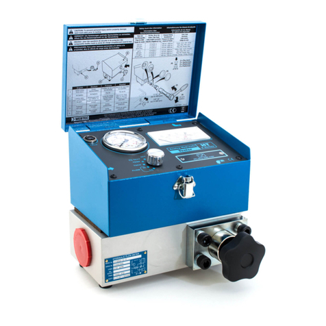
WEBTEC 1 Series User manual

English
Deutsch
FrançaisEspañol
1
1, 2 & 4 Series
Portable Hydraulic Testers User Manual
Bedienungsanleitung für tragbare Hydraulik
Testgeräte der Reihen 1, 2 und 4
Manuel d’utilisation des Testeurs Hydrauliques
portables des séries 1, 2 & 4
Manual de usuario de los Testers Hidráulicos
Portátiles Serie 1, 2 y 4
www.webtec.com

EU - English
This product contains a Bluetooth® Low Energy Module which broadcasts in the license free ISM Band as follows:
l2.402 to 2.480GHz
lChannels 0-39
lTransmit power: +7dBm
EU - Deutsch
Dieses Produkt enthält ein Bluetooth® Low Energy Modul, welches im lizenzfreien ISM-Band sendet und zwar wie folgt:
l2.402 bis 2.480GHz
lKanäle 0-39
lSende-Leistung: +7dBm
UE - Français
Ce produit contient un module basse consommation Bluetooth® qui fonctionne avec la licence gratuite ISM comme
ci-dessous :
l2.402 à 2.480GHz
l0-39 voies
lPuissance transmise: +7dBm
UE - Español
Este producto contiene un módulo Bluetooth® de energía baja que emite en la licencia libre ISM Band de la siguiente:
l2.402 a 2.480GHz
lCanales 0-39
lPotencia de transmisión: +7dBm
United States
Contains Transmitter Module FCC ID: T9JRN4020
This device complies with Part 15 of the FCC Rules.
Operation is subject to the following two conditions:
(1) this device may not cause harmful interference, and
(2) this device must accept any interference received, including interference that may cause undesired operation
This equipment has been tested and found to comply with the limits for a Class B digital device, pursuant to part 15 of
the FCC Rules. These limits are designed to provide reasonable protection against harmful interference in a residential
installation. This equipment generates, uses and can radiate radio frequency energy, and if not installed and used in ac-
cordance with the instructions, may cause harmful interference to radio communications. However, there is no guarantee
that interference will not occur in a particular installation. If this equipment does cause harmful interference to radio or
television reception, which can be determined by turning the equipment o and on, the user is encouraged to try to cor-
rect the interference by one or more of the following measures:
lReorient or relocate the receiving antenna.
lIncrease the separation between the equipment and receiver.
l Connect the equipment into an outlet on a circuit dierent from that to which the receiver is connected.
lConsult the dealer or an experienced radio/TV technician for help.
Canada
This device complies with Industry Canada license exempt RSS standard(s). Operation is subject to the following two
conditions:
(1) this device may not cause interference, and
(2) this device must accept any interference, including interference that may cause undesired operation of the device.
Le présent appareil est conforme aux CNR d’Industrie Canada applicables aux appareils radio exempts de licence.
L’exploitation est autorisée aux deux conditions suivantes: (1) l’appareil ne doit pas produire de brouillage, et (2)
l’utilisateur de l’appareil doit accepter tout brouillage radioélectrique subi, même si le brouillage est susceptible d’en
compromettre le fonctionnement.
Contains transmitter module IC: 6514A-RN4020
Under Industry Canada regulations, this radio transmitter may only operate using an antenna of a type and maximum (or
lesser) gain approved for the transmitter by Industry Canada. To reduce potential radio interference to other users, the
antenna type and its gain should be so chosen that the equivalent isotropically radiated power (e.i.r.p.) is not more than
that necessary for successful communication.
Conformément à la réglementation d’Industrie Canada, le présent émetteur radio peut fonctionner avec une antenne
d’un type et d’un gain maximal (ou inférieur) approuvé pour l’émetteur par Industrie Canada. Dans le but de réduire les
risques de brouillage radioélectrique à l’intention des autres utilisateurs, il faut choisir le type d’antenne et son gain de
sorte que la puissance isotrope rayonnée équivalente (p.i.r.e.) ne dépasse pas l’intensité nécessaire à l’établissement
d’une communication satisfaisante.
Meters with Bluetooth Contain Transmitter Module FCC ID: T9JRN4020 - IC: 6514A-RN4020
Tester mit Bluetooth enthalten Transmittermodul FCC ID: T9JRN4020 - IC: 6514A-RN4020
Débitmètres avec la fonctionnalité Bluetooth, contient un émetteur FCC ID: T9JRN4020 - IC: 6514A-RN4020
Medidores con Bluetooth contienen Módulo Transmisor FCC ID: T9JRN4020 - IC: 6514A-RN4020

English
1
Introduction
Webtec Portable Hydraulic Testers have been designed for easy connection to a hydraulic
circuit so that flow, pressure and temperature can be readily checked. Testers can take full
back pressure up to 210/420/480 bar (3000/6000/7000 psi) depending on the model, and the
built in loading valve enables many of the operating conditions to be simulated. The tester can
be connected anywhere in the hydraulic system to test pumps, motors, valves and cylinders
in both flow directions.
The tester range consists of the following types:
lDHT 1 Series Digital Hydraulic Tester
lHT 2 Series Analogue Hydraulic Tester
lDHT 2 Series Digital Hydraulic Tester
lDHM 4 Series Digital Hydraulic Multimeter
There are different sizes and porting options to cover a wide range of flows.
This manual covers all testers.
Before first operating the equipment read the whole of these instructions. Safety may be
impaired if they are not followed.
Webtec have been designing and manufacturing flow meters and hydraulics components
for over 50 years. We operate within a Quality Management System that complies with the
requirements of BS EN ISO 9001 which is externally audited and certificated each year.
Beyond compliance to the standard, Webtec is committed to continually improving in everything
we do; with particular emphasis on understanding what matters to our customers and suppliers,
and designing our systems and work to meet their needs. We are always keen to hear from
customer who may have special requirements not covered by our standard ranges.

English
2
Basic operation
Flow measurement
The tester measures flow using an axial turbine mounted in the aluminium base block. The
oil flow rotates the turbine and its speed is proportional to the oil velocity. The revolutions of
the turbine are measured by means of a magnetic sensing head which feeds a pulse every
time a turbine blade goes by to an electronic circuit. The electronic circuit has a built-in micro
processor; the signal is amplified and linearised to maximise accuracy. The readout is calibrated
in lpm or gpm, units are selectable on some models.
Pressure measurement
Where fitted, the pressure gauge has a spiral Bourdon tube and the gauge case is filled with
glycerine to ensure good dampening of pulsating pressures. The gauge is connected to the base
block by a fine bore capillary tube. The DHM series meters have a pressure transducer fitted
directly to the base block which improves fast transient capture. All testers are bi-directional
and incorporate a shuttle valve which directs the highest pressure (from inlet or outlet) to the
measuring point. A gauge port is provided on the back of the base block for the addition of a
low pressure gauge kit.
Temperature
The Thermistor temperature transducer is in contact with the oil flow and readout is on the meter
scale calibrated 32 - 250°F or 0 - 120°C.
Bi-Directional Loading Valve
The reverse flow valve gives positive shut-off and pressure control in both directions of flow.
The loading valve has two easily replaceable safety discs located in the valve assembly which
internally protect the tester and machine in both flow directions.
Installation guidance
lAll hydraulic connections should be made by suitably qualified personnel.
lAvoid sharp bends because high pressure hoses will deflect and straighten under pressure.
lA preliminary check of the hydraulic system’s oil supply, pump rotation, filters, oil lines,
cylinder rods as well as looking for external leaks should be made prior to installing the
Hydraulic Tester.
lAlthough the Bi-Directional tester can be used in both flow directions, the preferred direction
is indicated by the larger arrow on the panel. When the tester is used for reverse flow
tests, slightly lower accuracies may be obtained depending on the oil viscosity, density and
compressibility.
lThe tester should be connected to the hydraulic circuit by means of flexible hoses 1 - 2
metres long.
lThe use of quick-disconnect couplings can save time. Make sure the hoses are long enough
so that the tester can be used safely on the machine.
lThe hoses and fittings at the inlet to the tester must be of adequate size for the flow being
tested. Elbows, rotary couplings etc., at the inlet and outlet ports of the tester should be
avoided to ensure accurate readings.
lThe use of the flexible hoses will help to isolate the test unit from vibration which often exists.
lThe internal burst discs are to protect the tester not the hydraulic installation. Always ensure
the appropriate relief devices are fitted to protect the installation.

English
3
General Operation
All tests should be performed by suitably qualified personnel.
1. Connect the Tester to the circuit (see above for installation guidance)
2. Ensure that the pressure loading valve is fully opened by turning the knob counter clockwise.
3. Switch the unit on. On digital models if the display flashes, or on analogue models if the
needle points to the symbol, then the battery needs replacing.
4. Select the desired test using the front panel controls where applicable.
5. IMPORTANT: Ensure that all connections are tightened and the oil can flow freely throughout
the hydraulic system BEFORE running the machine at full speed. Check that the circuit is
correctly connected and any shut-off valves are opened. Also quick disconnect couplers
MUST be open.
6. Start the pump momentarily to ensure there is no obstruction which could cause pressure
build up.
7. Check for leaks and free flow of oil
8. The tester is now ready for use - run the machine and adjust the loading valve as needed
9. When the test is completed fully open loading valve.
Notes
When low pressure testing is required, connect the optional low pressure gauge with automatic
cut-out valve to the tester block.
Testers have an automatic electronic system which shuts the power off after approximately
20 minutes should you forget. To reactivate the tester, turn the selector switch to the “OFF /
RESET” position then back to ‘ON’.
Performance
All 600 & 800 models have limited pressure control below 86 lpm (23 USgpm). The maximum
controllable pressure in this region is calculated by: Max. pressure (in bar) = 5 x flow (lpm) +30.
Do not use with water
The standard Webtec Hydraulic Testers are designed for use with mineral oil having reasonable
lubrication properties. They are not suitable for use with water or fluids with a high water
content. If a tester is contaminated with water it should be flushed immediately with white or
methylated spirit or similar and then flushed with mineral oil to minimise any internal corrosion.
This may avoid an expensive repair. Damage to a tester from the use of a non-approved fluid
invalidates our normal warranty.

English
4
General Specification for all models
Ambient temperature: 5 to 40°C (41 - 104°F)
Fluid type: Mineral oil to ISO 11158 category HM
(for other fluid types please contact Sales).
Fluid temperature: DHT & HT - 0 to 120°C (32 - 250°F)
DHM - 0 to 105°C (32 - 220°F)
Accuracy: see model specifications
EMC Environment: This equipment is intended for use within industrial and residential
environments and does not suffer any degradation in operation when
subjected to test conditions according to requisite standards.
Construction materials
Case: Painted mild steel
Flow block: High tensile aluminium
Seals: FKM as standard - EPDM seals on request
Battery Details
PP3 9 volt Alkaline (IEC6LR61, ANSI/NEDA 1604A)
Dimensions and Weight
Model Height Width Depth Weight
DHT401
HT302/402 200 mm 240 mm 200 mm 6.5 kg
DHT302/402 7.87 inches 9.45 inches 7.87 inches 14.33 lbs
DHM404
DHT801
HT602/802 225 mm 245 mm 225 mm 10 kg
DHT602/802 8.86 inches 9.65 inches 8.86 inches 22 lbs
DHM804
Fluid viscosity
The performance of the tester can be affected by the viscosity of the fluid measured. Our testers
are calibrated at a mean viscosity of 21 cSt using ISO32 hydraulic mineral oil to ISO11158
category HM. The shaded area of the table shows the range of viscosities that can be measured
by a tester with standard calibration with minimal effect on the accuracy (less that ± 1% FS).
Table showing kinematic viscosity (cSt) of different mineral
oils at specific temperatures
Fluid type
Temp °C ISO15 ISO22 ISO32 ISO37 ISO46 ISO68
0 85.9 165.6 309.3 449.9 527.6 894.3
10 49.0 87.0 150.8 204.7 244.9 393.3
20 30.4 50.5 82.2 105.5 127.9 196.1
30 20.1 31.6 48.8 59.8 73.1 107.7
40 14.0 21.0 31.0 36.6 44.9 63.9
50 10.2 14.7 20.8 23.9 29.4 40.5
60 7.7 10.7 14.7 16.5 20.2 27.2
70 6.0 8.1 10.9 12.0 14.6 19.2
80 4.8 6.4 8.4 9.1 11.1 14.3
90 4.0 5.2 6.6 7.2 8.7 11.1
100 3.3 4.3 5.5 6.0 7.1 8.9
ISO 15, 22, 32, 46 and 68 based on typical figures for the Esso Nuto range of
HM oils. ISO 37 based on Shell Tellus HM oil.

English
5
Model Number Flow Range (lpm) Pressure Range (bar) Inlet/Outlet Ports
DHT401-B-6 10 - 400 0 - 420 1” BSPP
DHT801-S-7-L 20 - 800 0 - 480 1-7/8” -12UN #24 SAE ORB
DHT801-F-3-L 20 - 800 0 - 210* 1-1/2” SAE Code 61 4-Bolt Flange
Specification
EU (lpm/Centigrade)
US (gpm/Fahrenheit)
Flow Accuracy: ± 1% of full scale.
Pressure Accuracy: ± 1.6 % of full scale.
Temperature Accuracy: ± 1°C, 2°F.
* per J518 SAE Code 61 standard
Model Number Flow Range (gpm) Pressure Range (psi) Inlet/Outlet Ports
DHT401-S-6 2.5 - 100 6000 1-5/16” -12UN #16 SAE ORB
DHT801-S-7 5 - 210 7000 1-7/8” -12UN #24 SAE ORB
DHT801-F-3 5 - 210 3000* 1-1/2” SAE Code 61 4-Bolt Flange
DHT 1 Series Digital Hydraulic Tester
Digital display Pressure gauge
Battery coverOn/Off switch

English
6
HT 2 Series Analogue Hydraulic Tester
Tachometer
input Pressure gauge Battery
voltage low Battery
voltage ok
Display
(flow, temp, rpm)
Battery coverSelector switch
lTachometer input - Connection socket for the optional infra-red phototachometer.
lSelector switch - Turn the switch to select the required function.
lOFF/RESET - Switches the tester off and resets the unit after automatic power shut off.
l‘B’ TEST - Checks the condition of the battery.
lTEMP - Temperature is indicated on the display.
lTACH - RPM is indicated on the display.
lFLOW ‘HI’ - Flow is indicated on the ‘Hi’ scale of the display.
lFLOW ‘LO’ - Flow is indicated on the ‘LO’ scale of the display.

English
7
Model Flow Flow Scales Pressure Speed Inlet/Outlet
Number Range (lpm) Range (rpm) Ports
(lpm) Low High (bar)
HT302-B-6 8 - 300 0 - 75 0 - 300 0 - 420 300 - 3000 1” BSPP
HT402-B-6 10 - 400 0 - 100 0 - 400 0 - 420 300 - 4000 1” BSPP
HT602-S-7 20 - 600 0 - 150 0 - 600 0 - 480 300 - 6000 1-7/8” -12UN #24 SAE ORB
HT802-S-7 20 - 800 0 - 200 0 - 800 0 - 480 300 - 5000 1-7/8” -12UN #24 SAE ORB
Specification
EU
US
Flow Accuracy: ± 1% of full scale.
Pressure Accuracy: ± 1.6% of full scale.
Temperature Accuracy: ± 2°C, 4°F.
Speed: Needs optional infra-red phototachometer using one or more retro-reflective marks.
Range: See Table.
Accuracy: ± 2% of full scale.
* per J518 SAE Code 61 standard
Model Flow Flow Scales Pressure Speed Inlet/Outlet
Number Range (gpm) Range (rpm) Ports
(gpm) Low High (psi)
HT302-S-6 2 - 80 0 - 20 0 - 80 6000 300 - 3000 1-5/16” -12UN #16 SAE ORB
HT402-S-6 2.5 - 100 0 - 25 0 - 100 6000 300 - 4000 1-5/16” -12UN #16 SAE ORB
HT602-F-3 5 - 160 0 - 40 0 - 160 3000* 300 - 6000 1-1/2” SAE Code 61 4-Bolt Flange
HT602-S-7 5 - 160 0 - 40 0 - 160 7000 300 - 6000 1-7/8” -12UN #24 SAE ORB
HT802-F-3 5 - 210 0 - 50 0 - 210 3000* 300 - 5000 1-1/2” SAE Code 61 4-Bolt Flange
HT802-S-7 5 - 210 0 - 50 0 - 210 7000 300 - 5000 1-7/8” -12UN #24 SAE ORB

English
8
DHT 2 Series Digital Hydraulic Tester
Digital display
Battery coverExternal
flow
Tachometer
input
Selector switch
lChange settings indicated by the ^ on the display - using the °C/°F and UNITS buttons.
The FAST button changes the screen refresh from 1 to 3 times per second.
lTachometer input - Connection socket for the optional infra-red phototachometer.
lExternal flow - Connection socket for optional second ‘LT’ series flow meter, to measure a
second flow and temperature.
lSelector switch - Turn the switch to select the required function.
lOFF - Switches the tester off and disconnects the battery.
lTACH - RPM is indicated on the display.
lINT FLOW - Display flow and temperature measured by the internal flow meter.
lEXT FLOW - Display flow and temperature measured by the optional external flow
meter.
Pressure gauge

English
9
Model Flow Range Pressure Range Speed Inlet/Outlet Ports
Number (lpm) (bar) (rpm)
DHT302-B-6 8 - 300 0 - 420 300 - 6000 1” BSPP
DHT402-B-6 10 - 400 0 - 420 300 - 6000 1” BSPP
DHT602-F-3-L 20 - 600 0 - 210* 300 - 6000 1-1/2” SAE Code 61 4-Bolt Flange
DHT602-S-7-L 20 - 600 0 - 480 300 - 6000 1-7/8” -12UN #24 SAE ORB
DHT802-F-3-L 20 - 800 0 - 210* 300 - 6000 1-1/2” SAE Code 61 4-Bolt Flange
DHT802-S-7-L 20 - 800 0 - 480 300 - 6000 1-7/8” -12UN #24 SAE ORB
Specification
EU (lpm/Centigrade)
US (gpm/Fahrenheit)
Flow Accuracy: ± 1% of indicated reading (over 15 - 100% of range).
Pressure Accuracy: ±1.6% of full scale.
Temperature Accuracy: ± 1°C, 2°F.
Speed: Needs optional infra-red phototachometer using one or more reflective marks.
Range 300 - 6000 rpm. Accuracy: ± 1/4% of full scale with one count per revolution.
* per J518 SAE Code 61 standard
Model Flow Range Pressure Range Speed Inlet/Outlet Ports
Number (gpm) (psi) (rpm)
DHT302-S-6 2 - 80 6000 300 - 6000 1-5/16” -12UN #16 SAE ORB
DHT402-S-6 2.5 - 100 6000 300 - 6000 1-5/16” -12UN #16 SAE ORB
DHT602-F-3 5 - 160 3000* 300 - 6000 1-1/2” SAE Code 61 4-Bolt Flange
DHT602-S-7 5 - 160 7000 300 - 6000 1 7/8” -12UN #24 SAE ORB
DHT802-F-3 5 - 210 3000* 300 - 6000 1-1/2” SAE Code 61 4-Bolt Flange
DHT802-S-7 5 - 210 7000 300 - 6000 1 7/8” -12UN #24 SAE ORB
Program Mode - EXT, INT and TACH.
External Flow - EXT
1. Turn selector switch to Ext.Flow.
2. Press °C/°F button and hold down. Then press ON i.e. two buttons are pressed at the same time.
3. On the left side of the display appears the turbine type number i.e. 750 is 750 lpm, on the right
side of the display is the standard calibration number. Use the FAST key to browse through the
list of turbine types. Press UNITS to select a turbine type.
4. Use the FAST key to increment the number above the cursor. Press UNITS to move to the
next column. After entering the calibration factor press UNITS until the display overflows. The
display will now show the number of digits after the decimal point. Use the FAST key to select
the number of decimal places to appear on the display.
5. Press the ON button to store the entries.
Internal Flow - INT
The internal calibration factor can be loaded by switching to INT and repeating the program
instructions above.
TACH
The calibration factor for RPM is pre-programmed for a factor of 1.0. For the RPM/N function
the tachometer provides N pulses per revolution of the shaft.
To set factor N:
1. Turn selector switch to TACH.
2. Press °C/°F button and hold down. Then press ON i.e. two buttons are pressed at the same time.
3. The display shows the current value for “N”. Use the FAST key to increment the number above
the cursor. Press UNITS to move to the next column.
4. Press the ON button to store the entries.

English
10
lContrast up - Press & hold to make the screen text darker and easier to read in dierent
light conditions.
lContrast down - Press & hold to make the screen text lighter.
lRecord data – Pressing this button when viewing live data (screen 1, 2 or 3) will record the
current values.
lToggle screen - This button toggles through the four display screens, three live data views
and the record review screen.
lToggle between temperature & power (P-Q) - Pressing this button will change the
bottom line of the display from temperature to power. This button is also used to start the
eciency display on screen 3.
lClear peak - Press to clear the peak pressure value
lToggle pressure and power units - Toggles through a selection of engineering units for
pressure and the corresponding power units.
lON/OFF button – A momentary press turns the unit ON. Press and hold for 2sec to turn
OFF.
DHM 4 Series Digital Hydraulic Multimeter
Toggle
screen Clear peakToggle:
temperature
& power
Toggle
pressure and
power units
Battery
cover
Record
Data
Digital display
Contrast
up Contrast
down On/Off switch

English
11
Model Number Flow Range (lpm) Pressure Range (bar) Inlet/Outlet Ports
DHM404-B-6 10 - 400 0 - 420 (0 - 600 peak) 1” BSPP
DHM804-S-7-L 20 - 800 0 - 480 (0 - 600 peak) 1-7/8” -12UN #24 SAE ORB
Specification
EU (lpm/Centigrade)
US (gpm/Fahrenheit)
Flow
The EU version displays flow in lpm, the US version displays flow in gpm.
Accuracy: ± 1% of indicated reading (over 15 - 100% of range).
Pressure and peak pressure
Measured using a built-in pressure transducer rated to 600 bar / 8700 psi. The transducer
has a typical response time of <1 ms to enable the accurate capture of peak pressures. The
meter samples the pressure transducer 1000 times per second and updates the peak display
appropriately. The engineering units for pressure can be changed using the ‘pressure units’
button on the front panel. Standard units are ‘BAR, PSI, MPA, KSC’.
Accuracy: Pressure 0.5% FSD, Peak 1% FSD.
Peak Pressure: capture rate = 1ms
Temperature
Sensed by a thermistor built into the flow transducer to maximise contact with the oil flow
and ensure fast response. The EU version displays temperature in °C, the US version displays
temperature in °F.
Accuracy: ± 1°C, 2°F.
Power
Calculated from the flow and pressure, the hydraulic power is displayed in either HP or KW.
The engineering units for power are linked to the pressure units and can be changed using the
‘pressure units’ button on the front panel.
Accuracy: ± 3 kW / 4 HP (≤ 100 kW / 134 HP), ± 5 kW / 6.7 HP (> 100 kW / 134 HP).
Volumetric efficiency
Calculated as a ratio of the flow at high pressure to the flow under reference conditions.
Volumetric Efficiency is expressed as a percentage, at constant rpm.
Accuracy: ± 1% point.
Data Recording: up to 12 sets of data points can be saved to internal memory
LCD Display: High contrast, fast response 4 line display. Update rates of measurements:
Digital values @1.4Hz
Analogue bars @ 14Hz
Peak Pressure capture @1ms
Battery Life: approximately 15 hours of normal use with high capacity Alkaline unit.
IP54 Internal Protection of electronic circuits.
iOS® App’
Application programs are only available for phones or tablets running iOS operating systems.
Handheld devices must support Bluetooth® Smart (v4.1) or greater.
Apple iOS v8.1 or higher.
NB. For Apple iPhone 5S upwards.
Model Number Flow Range (gpm) Pressure Range (psi) Inlet/Outlet Ports
DHM404-S-6 2.5 - 100 0 - 6000 (0 - 8700 peak) 1-5/16” -12UN #16 SAE ORB
DHM804-S-7 5 - 210 0 - 7000 (0 - 8700 peak) 1-7/8” -12UN #24 SAE ORB
Visit the iTunes® store and download the Webtec Quick Cert App’ to your mobile device.

English
12
This screen displays the measurement type, value and engineering units in digital format.
Bottom line displays either Power or Temperature depending on selection.
This screen displays the measurements in the same order as in SCREEN 1, but this time
displays the value, engineering units and a bar graph which corresponds to the value
indicated. The bar graph is scaled from zero to the maximum value for the tester (see below).
Bottom line displays Power or Temperature depending on selection.
NB. Analogue bars update @14Hz to provide a visual indication of rapid activity.
Screen 1 (Digital)
Screen 2 (Analogue)
Screen 3 (P - Q)
Bar graph scaling: EU US
DHM404 DHM804 DHM404 DHM804
Flow LPM 0 - 400 0 - 800 GPM 0 - 100 0 - 210
Pressure BAR 0 - 600 0 - 600 PSI 0 - 8700 0 - 8700
Peak BAR 0 - 600 0 - 600 PSI 0 - 8700 0 - 8700
Temperature °C 0 - 120 0 - 120 °F 32 - 250 32 - 250
Power kW 0 - 400 0 - 800 HP 0 - 536 0 - 1072
This screen is used for testing pump volumetric efficiency. The screen initially displays flow
and pressure on the top two lines as in SCREEN 2 and power on the bottom two lines. Once
the efficiency reference point has been captured, then the third line displays the current
efficiency and the bottom line shows the reference point, the top two lines will continue to
display the current flow and pressure.
Screen 4 (Data Review)
This screen displays any recorded parameters and provides delete options.

English
13
To turn the meter ON press this button momentarily.
To turn the meter OFF press and hold this button.
As the meter turns on two information screens display status data including:
lCurrent version of software running on the meter.
lTotal run time in minutes.
lTurbine type.
lTurbine calibration number.
lCalibration date.
lMeter serial number.
After the two information screens the meter reverts to the previously used display screen.
Note: Low battery warning is issued by the display screen flashing. Reliable operation
cannot be expected in these circumstances - the battery must be replaced.
DHM Operation
As pressure changes the actual and peak values are updated on the display. Peak
pressure is captured at a typical rate of 1ms, allowing the display of rapid transition
spikes, otherwise missed.
Pressing the P-Q button while on screen 1 will toggle the bottom line, temperature
display between power and temperature.
When the meter is turned ON the contrast buttons can be used to adjust the display
to suite the ambient light conditions. Settings are saved.
Pressing the clear peaks button clears the peak capture memory.
Pressing the pressure units button scrolls through the available pressure engineering
units. If power is being displayed, then its engineering units will change to suite the
selected pressure units.
Pressing the screen selection button scrolls through the four available screens: digital
display, digital + bar graphs, power/efficiency and record review.
Pressing the P-Q/HP button while in screen 3 initiates the efficiency display. It
captures the flow and pressure to memory and treats this as the 100% reference
point. The bottom line of the display shows the flow and pressure that are saved as
the reference marker:
Holding the clear peaks button at power on will toggle the temperature units.
Holding the pressure units button at power on will toggle the flow units.
Holding both buttons at power on will toggle the temperature and flow units.
+
+
+

English
14
In efficiency mode, as the flow and pressure vary the % value on line 3 changes to
indicate the difference from the starting point:
Pressing the record button while in screens 1, 2 or 3 (live data view) will save the
instantaneous flow pressure and temperature values to memory. If there is available
memory the display acknowledges by displaying “SAVED”. If there is no available
memory the display warns “MEMORY FULL”.
This is screen 4, recorded data review and delete screen:
This display shows a table of captured data points that can be navigated by the ‘soft
menu’ keys designated on the bottom line.
Clear peaks button becomes the scroll “UP” key.
Pressure unit’s button becomes the scroll “DWN” key.
PQ/HP button becomes the “DEL” key.
The ‘soft menu’ action of these buttons allows the user to scroll up and down the
recorded data table with an option to delete data.
The delete options are indicated by ‘soft menu’ designators on line 4 and allow either
the last data item or all data items to be erased.
Failure to connect to mobile device
If there are persistent failures when attempting to Import data with a mobile device
the following reset procedure may help:
lTurn the meter OFF
lHold down the REC button and turn the meter ON. Keep the REC button pressed
until normal display screen appears.

English
15
Maintenance and service
Battery replacement
lTurn tester off.
lLoosen the two screws either end of the battery cover.
Note: They are captive screws.
lCarefully remove battery and disconnect.
lConnect new PP3 battery (See General Specification for details), place in tester and replace
battery cover.
Note: Only replace with similar size and type of battery.
Calibration
Recommended period between calibrations is 12 months. Maximum period between calibrations
is 36 months. Unit accuracy may be affected by operating cycle, fluid condition or extended
periods between recalibrations.
Testers can be specially calibrated at a different viscosity to the standard, please contact sales
for further information.
Accessories
Low pressure gauge kit - comprises 63 mm Glycerine filled 40 bar (600 psi) gauge with
automatic cut-out valve, pressure test point and 300 mm (12”) long micro bore hose. The test
point is fitted permanently into the tester block and the low pressure gauge can be connected
by hand without the need to stop the machine.
For 2 series testers only: Infrared photo tachometer comprises infrared photo tach head, six
metre connecting cable and reflective tape. The BA20 magnetic base with flexible arm is also
available, this is used to secure the tacho head on the machine.
A range wide range of general accessories are available, these include pressure transducers, high
pressure temperature sensors adaptors, cables and remote displays, please consult sales office
Only use Webtec approved parts and accessories, using other parts could cause permanent
damage to the tester or comprise safety.
lDisconnect the tester from the hydraulic
circuit
lLocate the new discs - the tester is shipped
with spare discs located in the block
lScrew the load valve fully shut - (clockwise)
lUnscrew the safety disc holder from the valve
lRemove the disc spacer and ruptured discs
from the valve and disc holder
lCarefully shape the two new discs by pressing
them by hand between the disc holder and
spacer
lPlace the first disc inside the valve
lReplace the spacer
lPlace the second disc on top of the spacer
lScrew in the disc holder, tighten to 54 Nm
(40 lb.ft)
lUnscrew the load valve fully
lRe-connect the tester if required
Replacement of burst discs

Garantía limitada del fabricante de 5 años
Webtec Products Ltd. garantiza al comprador original, durante un periodo de cinco años a partir de la fecha de compra, que todos los testers
hidráulicos nuevos estarán libres de defectos materiales y de mano de obra.
Esta garantía no incluye ningún tester hidráulico que haya resultado dañado debido al abuso o funcionamiento más allá de las especificaciones
máximas indicadas por Webtec Products Ltd. en la literatura asociada con el tester hidráulico o mediante su uso con líquidos incompatibles.
La única obligación de Webtec Products Ltd. al amparo de esta garantía está limitada a la reparación o sustitución de piezas gratis, siempre y
cuando las mismas demuestren estar defectuosas después de la inspección realizada por Webtec Products Ltd. o por una de sus divisiones.
La reparación o sustitución de las piezas defectuosas será a la absoluta discreción de Webtec Products Ltd.
Antes de devolver cualquier tester hidráulico al amparo de esta garantía es necesario obtener el consentimiento escrito de Webtec Products
Ltd. Los gastos de envío y manipulación están cubiertos durante los 12 primeros meses de la fecha de compra. Después de 12 meses de la
fecha de compra, los gastos de envío y manipulación no están cubiertos por la garantía.
Webtec Products Ltd. no es responsable de ningún daño indirecto ni de cualquier responsabilidad contingente que pueda surgir del fallo de
cualquier tester hidráulico, componente, pieza o accesorio.
Esta garantía sustituye y se ofrece en lugar de cualquier otra garantía, expresa o implícita y de cualquier otra obligación o responsabilidad.
Ningún agente, representante o distribuidor está autorizado a modificar en forma alguna los términos de esta garantía.
Cinq ans de garantie fabricant
Webtec Products Ltd. garantit à l’acheteur initial que pendant la période de cinq années qui suit l’achat, tout nouveau testeur hydraulique est
exempt de défaut de fabrication et de matériaux.
Cette garantie ne couvre pas les testeurs hydrauliques détériorés par une utilisation abusive, ou utilisés au dessus des spécifications maximales
établies par Webtec Products Ltd. dans les documentations techniques associées, ou encore par l’utilisation d’un fluide incompatible.
Dans le cadre de la garantie, l’unique obligation de Webtec Products Ltd. se limite, à titre gratuit, à la réparation ou remplacement des pièces que
Webtec Products Ltd. ou une de ses divisions aura trouvées défectueuses. La réparation ou le changement des pièces se fera à notre discrétion.
Une autorisation écrite de Webtec Products Ltd est requise avant tout retour, sous garantie, d’un testeur hydraulique. Les frais de transport
et de garde sont couverts durant les 12 mois qui suivent la date d’achat. 12 mois après la date d’achat, les frais de transport et de garde ne
sont plus couverts par la garantie.
Webtec Products Ltd. n’est en aucun cas responsable des dégâts causés ou des éventuelles conséquences qui résulteraient d’un défaut d’un
testeur hydraulique, d’une pièce ou d’un accessoire.
La garantie présentée ci-dessus supplante et prend la place de toutes les autres garanties, exprimées ou impliquées ainsi que les autres obligations
et responsabilités. Aucun agent, revendeur ou distributeur, en aucun cas, n’a le pouvoir ou l’autorité de modifier les termes de cette garantie.
Fünf Jahre begrenzte Garantie des Herstellers
Webtec Products Ltd. garantiert an den Erstkäufer, über einen Zeitraum von fünf Jahren ab Verkaufsdatum, dass jeder neue Hydrauliktester
frei von Fehlern in Material und Verarbeitung ist.
Diese Garantie erstreckt sich nicht auf Hydrauliktester, welche durch Missbrauch, fehlerhafter Bedienung oder Bedienung über die Grenzen des
Testers (wie von Webtec Products Ltd in der Literatur angegeben) hinaus, entstanden sind. Ferner durch die Verwendung von nicht geeigneten
Flüssigkeiten.
Die einzige Verpflichtung von Webtec Products Ltd. unter dieser Garantie, ist beschränkt auf die kostenlose Reparatur oder den Ersatz von
Teilen, welche für defekt befunden wurden, nach einer Inspektion von Webtec Products Ltd, oder einer ihrer Divisionen. Reparatur oder Ersatz
von Teilen erfolgt nach Ermessen von Webtec Products Ltd.
Schriftliche Ermächtigung durch Webtec Products Ltd ist notwendig, bevor ein Tester unter Garantie retourniert werden darf. Versand- und
Bearbeitungsgebühren sind, während den ersten 12 Monaten ab Verkaufsdatum, gedeckt. Nach 12 Monaten ab Verkaufsdatum sind Versand-
und Bearbeitungsgebühren nicht durch die Garantie gedeckt.
Webtec Products Ltd. ist nicht haftbar für Folgeschäden oder Folgekosten, welche durch einen Ausfall oder einer Fehlfunktion eines
Hydrauliktesters, Zubehörs, Teile davon oder Komponententeile entstehen könnten.
Obige Garantie ersetzt und ist anstelle aller anderen Garantien, welche angeführt oder angedeutet wurden und anstelle aller anderen
Verpflichtungen und Verbindlichkeiten. Kein Wiederverkäufer, Agent oder Distributor hat ein Recht die Konditionen dieser Garantie in
irgendeiner Weise zu ändern.
Manufacturer’s Five Year Limited Warranty
Webtec Products Ltd. warrants to the original purchaser, for the period of five years from the date of purchase, that each new hydraulic tester
is free from defect in materials and workmanship.
This warranty does not cover any hydraulic tester that has been damaged due to abuse or operation beyond the maximum specifications stated
by Webtec Products Ltd. in the associated hydraulic tester literature or by use on incompatible fluids.
Webtec Products Ltd. sole obligation under the warranty is limited to the repair or the replacement of parts, at no charge, found to be defective
after inspection by Webtec Products Ltd. or one of its divisions. Repair or replacement of parts will be at Webtec Products Ltd. discretion.
Written authorisation from Webtec Products Ltd. is required before any hydraulic tester can be returned under warranty. Cost of shipping and
handling is covered during the first 12 months from the date of purchase. After 12 months from the date of purchase, cost of shipping and handling
is not covered by the warranty.
Webtec Products Ltd. is not liable for any consequential damages or any contingent liabilities arising out of the failure of any hydraulic tester,
component part or accessory.
The above warranty supersedes and is in place of all other warranties, either expressed or implied and all other obligation or liabilities. No
agent, or representative or distributor has any authority to alter the terms of this warranty in any way.

Designed and produced by Webtec - Entwickelt und hergestellt von Webtec
Conçu et produit par Webtec - Diseñado y producido por Webtec TESTERS-MA-MUL-1812.pdf FT10049 Issue J 03/17
Webtec reserve the right to make improvements and changes to the specification without notice.
Webtec behält sich das Recht vor, Verbesserungen oder Änderungen der Spezifikationen ohne Ankündigung vorzunehmen.
Webtec se réserve le droit d’améliorer et de changer ses spécifications sans préavis.
Webtec se reserva el derecho de realizar mejoras y cambios a las especificaciones sin previo aviso.
For Sales & Service contact
Auskunft & Beratung
Contact Service commercial & maintenance
Para más información sobre ventas y servicios contactar con
Distributor - Vertriebspartner - Distributeur - Distribuidor
Certificate No.8242
Please do not return goods without written authorisation
Bitte keine Waren ohne schriftliche Genehmigung retournieren
Veuillez ne pas retourner d’appareil sans autorisation écrite
Favor de no devolver mercancías sin autorización por escrito
St. Ives, Cambs, PE27 3LZ, UK
中国:
Tel: +852-34624900 - [email protected]
France
Deutschland
U.S.A & Mexico
www.webtec.com
Other manuals for 1 Series
1
This manual suits for next models
10
Table of contents
Other WEBTEC Test Equipment manuals