OfiTE 150-50 User manual

Dierential Sticking Tester
Part No. 150-50
Instruction Manual
Updated 11/28/2023
Ver. 4
OFI Testing Equipment, Inc.
11302 Steeplecrest Dr. · Houston, Texas · 77065 · U.S.A.
Tele: 832.320.7300 · Fax: 713.880.9886 · www.ote.com
©Copyright OFITE 2013

OFITE, 11302 Steeplecrest Dr., Houston, TX 77065 USA / Tel: 832-320-7300 / Fax: 713-880-9886 / www.ote.com 1
Intro..................................................................................................2
Description ......................................................................................2
Components ...................................................................................3
Safety ...............................................................................................5
Test Procedure ...............................................................................6
Timed Filtration ...........................................................................6
Disassembly ................................................................................. 11
Theory............................................................................................12
Example ....................................................................................14
Worksheet.................................................................................15
Maintenance ..................................................................................16
Diagrams .......................................................................................17
Full Unit.....................................................................................17
Cell Assembly ...........................................................................18
Warranty and Return Policy ........................................................19
Table of
Contents

OFITE, 11302 Steeplecrest Dr., Houston, TX 77065 USA / Tel: 832-320-7300 / Fax: 713-880-9886 / www.ote.com 2
The OFITE Dierential Sticking Tester measures the “Stuck Pipe Tendency
Coecient” of drilling uids, and also determines how eective lubricants or
treatments might be with any given drilling uid. This coecient takes into ac-
count both the friction, or “stickiness”, of the lter cake, as well as the amount
of cake building that must occur in order to freeze or stick the pipe in the hole.
The coecient is determined by running a Timed Filtration test. By measuring
the area of cake building during a test, the “Bulk Sticking Coecient” is ob-
tained and read directly at the conclusion of the test. How likely a given uid
will be to produce a stuck pipe situation and how eective a given treatment
may be, can be immediately determined on-site.
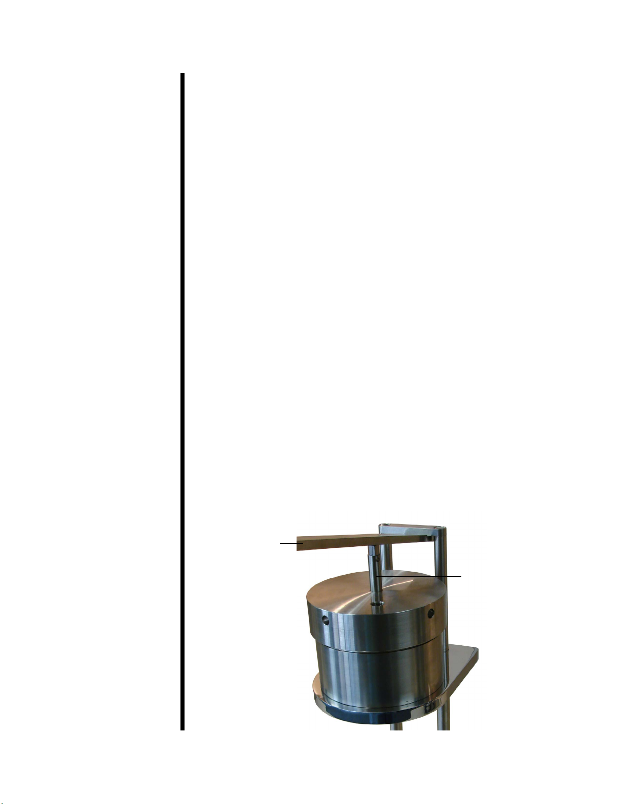
The unit is normally pressurized by a CO2 pressuring assembly, but any
nitrogen source will also work. If nitrogen is used, the tester apparatus must
be tted with a suitable nitrogen regulator, gauges, valves, and high-pressure
hoses. The standard test uses 477.5 PSI (3,291 kPa) applied to a 200-mL
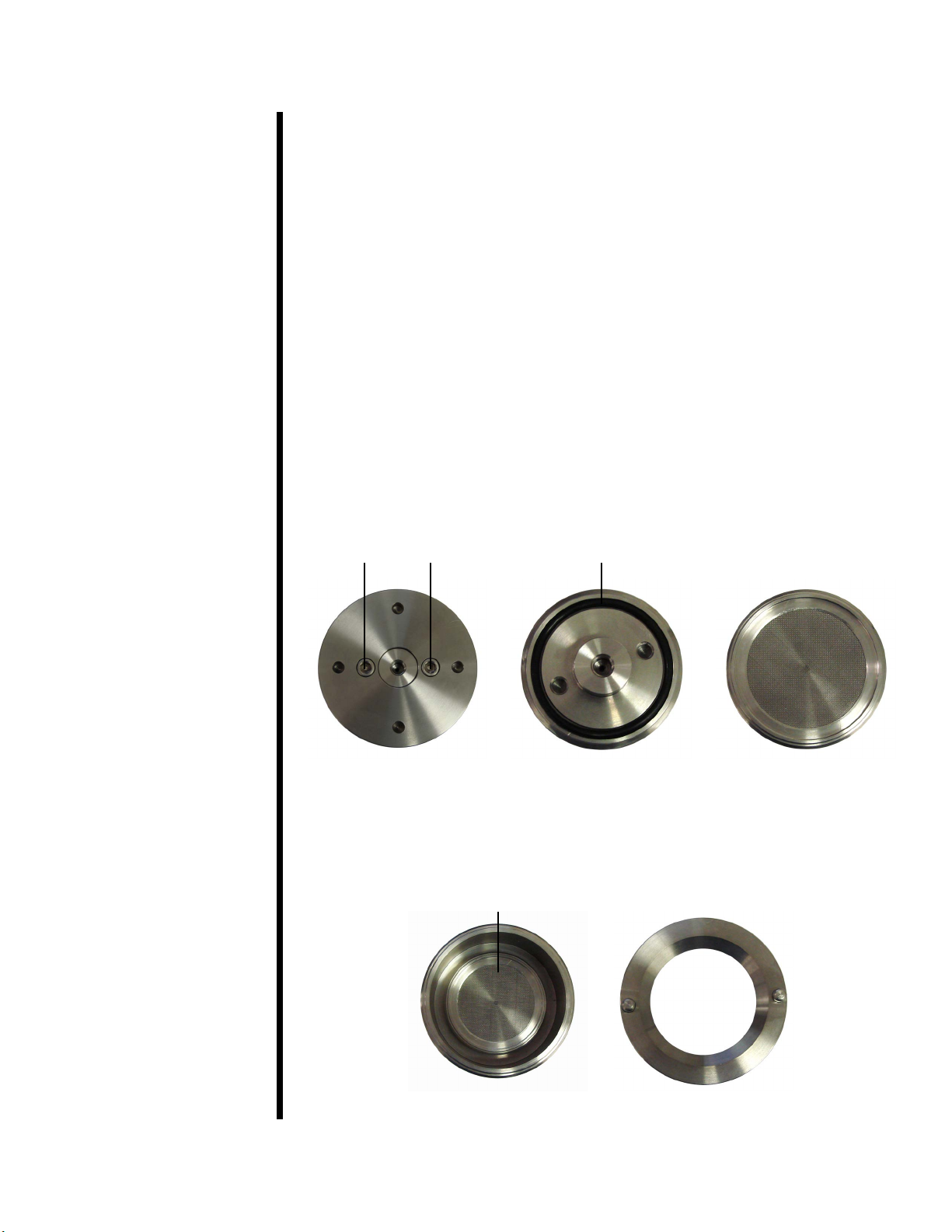
stainless steel vessel. The unit includes both a at-faced plate and a plate of
12½" (31.75 cm) spherical radius, which simulates the pipe inside the casing
or collars in the borehole. For samples that adhere more to the plate than to
the lter paper, stainless steel micro-corrugation disks are provided. For con-
venience a stainless steel carrying case is available as an optional item.
Intro
Description

OFITE, 11302 Steeplecrest Dr., Houston, TX 77065 USA / Tel: 832-320-7300 / Fax: 713-880-9886 / www.ote.com 3
Components #130-10-52 Jam Nut, 3/8-24, Qty: 2
#142-56 O-ring
#150-52 Neoprene Gasket
#150-53 Plastic Gasket
#150-54 Torque Wrench
#150-55 Spanner Wrench
#150-56 Test Cell O-ring
#150-57 5⁄1 6 " Socket with ⅜" Drive
#150-58 Torque Plate, Flat Bottom
#150-59 Torque Plate, Spherical
#153-16 Glass Graduated Cylinder, 25 mL × 2⁄1 0 mL
#170-04 CO2 Pressurization Unit:
#143-02-10 CO2 Puncture Head Assembly
#143-03 Barrel for CO2 Cartridge
#170-08 Regulator
#170-20 Manifold Block
#170-32 ⅛" × ⅛" NPT Male Needle Valve
#171-22 Retainer Pin
#171-34 1500-PSI Gauge, 2", ¼" NPT Bottom
#170-13-3 Test Cell O-ring, Viton 75D
#170-15 Base
#170-16 Valve Stem, Qty: 2
#170-17 Valve Stem O-ring, Qty: 10
#170-19 2½" (6.35 cm) Filter Paper, Specially Hardened for Filter
Presses
#170-35 6" Adjustable Wrench
#170-44 ½" Rubber Foot, Qty: 4
#171-79 ¼" Hex Wrench

OFITE, 11302 Steeplecrest Dr., Houston, TX 77065 USA / Tel: 832-320-7300 / Fax: 713-880-9886 / www.ote.com 4
Optional:
#150-50-SP Spare Parts for #150-50:
#142-56 O-ring, Qty: 12
#143-02-13 O-ring for Puncture Pin Holder Assembly, CO2 Cartridge,
Qty: 4
#143-02-14 O-ring for Puncture Pin Holder Assembly, Qty: 4
#143-05 EZ Puncture CO2 Bulbs, 8-Gram, UN #1013, Package of
10, Qty: 20
#143-07 Regulator Repair Kit for #143-00
#143-22 Gasket for Puncturing Pin, Qty: 6
#150-51 Locking Mesh Disc, Qty: 10
#150-52 Neoprene Gasket, Qty: 10
#150-53 Plastic Gasket, Qty: 8
#153-16 Glass Graduated Cylinder, 25 mL × 2⁄1 0 mL, Qty: 2
#170-13-3 Test Cell O-ring, Viton 75D, Qty: 4
#170-16 Valve Stem, Qty: 2
#170-17 Valve Stem O-ring, Qty: 20
#170-19 2½" (6.35 cm) Filter Paper, Specially Hardened for Filter
Presses, Qty: 5
#170-23 60-Mesh Screen, Qty: 4
#171-23-1 Safety Pin with Lanyard
#171-79 Hex Wrench, ¼"

OFITE, 11302 Steeplecrest Dr., Houston, TX 77065 USA / Tel: 832-320-7300 / Fax: 713-880-9886 / www.ote.com 5
Safety Nitrogen must be supplied in an approved Nitrogen Gas Cylinder and se-
cured to meet safety standards. Do not use nitrous oxide cartridges as pres-
sure sources.
Due to the high pressures involved in this test, extreme care must be exer-
cised at all times. All safety precautions must be met, especially in the cell
breakdown procedure after the ltration procedure has been completed.
Never transport CO2 bulbs or cartridges by airplane without proper packag-
ing. Cabin depressurization could cause them to explode.
Before pressuring, always check to be sure the regulator is in a closed posi-
tion by ensuring the T-screw is backed out and free turning. Insert and punc-
ture the CO2 cartridge by turning the barrel only a quarter turn past the actual
puncture point. Adjust the regulator to the desired pressure with the regulator
T-screw. With the Dierential Sticking Tester, never exceed 500 PSI (3,450
kPa). When depressurizing, shut o the pressure supply, then bleed o the
system of pressure with the valve, and nally back out the regulator T-screw.

OFITE, 11302 Steeplecrest Dr., Houston, TX 77065 USA / Tel: 832-320-7300 / Fax: 713-880-9886 / www.ote.com 6
Test
Procedure
Timed Filtration
Two torque plates are provided with the unit. The spherical torque plate
(#150-59) has a very slight curve on the bottom. The radius of the curve is
12.5" (31.75 cm) and simulates a 25" (63.5 cm) diameter drill casing or collar.
The at torque plate (#150-58) is completely at across the surface. The dif-
ference between the two is sometimes dicult to see. To distinguish between
the two, place them next to each other on a at surface. The spherical torque
plate will rock slightly, while the at torque plate will sit rmly.
1. Make sure the unit is clean and dry before beginning a test.
2. Open the test cell. Remove the inner cap by turning the cell over and
removing the two allen screws with the supplied wrench.
3. Inspect the o-ring on the bottom of the inner cap. Replace it if it shows
signs of wear or damage.
Allen Screws O-ring
Inner Cap
Cell Bottom Inner Cap - Bottom Inner Cap - Top
Cell - Inside Retaining Ring

OFITE, 11302 Steeplecrest Dr., Houston, TX 77065 USA / Tel: 832-320-7300 / Fax: 713-880-9886 / www.ote.com 7
4. Place a sheet of lter paper on top of the screen on the inner cap. On top
of the lter paper, place the rubber gasket, then the plastic ring.
The locking mesh disk can be used to lock the lter cake to the paper so
that it does not stick to the torque plate face and break lose from the lter
paper. If you choose to use the locking mesh disk, place it on top of the
lter paper, beneath the rubber gasket.
5. Screw the retaining ring in place on top of the lter paper and gaskets. Be
sure to keep the gaskets centered.
6. Place the inner cap back into the cell. Make sure the o-ring seats properly
beneath the inner cap. Refer to the photos on page 8.
7. Turn the cell over and secure the inner cap with the two allen screws.
8. Tighten the retaining ring securely with the supplied retainer wrench.
9. Inspect the o-rings on the valve stems and replace any that show signs of
wear or damage. Screw one of the valve stems into the hole in the base
of the test cell and hand tighten.
Retainer Wrench (#150-55)
Retaining Ring (#150-50-002)
Plastic Gasket (#150-53)
Neoprene Gasket (#150-52)
Locking Mesh Disk (#150-51)
Filter Paper (#170-19)
Inner Cap with Screen
(#150-50-009)

OFITE, 11302 Steeplecrest Dr., Houston, TX 77065 USA / Tel: 832-320-7300 / Fax: 713-880-9886 / www.ote.com 8
10. Place the cell on the stand. Make sure the four holes in the base of the
cell line up with the stand tips.
11. Fill the cell with sample uid to the scribed line.
12. Insert the stem of the torque plate through the hole in the cell cap as far
as possible. The face of the plate should be facing towards the inside of
the cell. Be careful not to cut the o-ring.
13. Screw the cell cap onto the test cell body. Make sure the o-ring is properly
seated in the groove in the cell cap.
14. Tighten the cell cap using the supplied spanner wrench. For additional
leverage, place the lever arm horizontally between the two support legs.
Once the cell cap is tightened, rotate the cell on the stand until the valve
stem hole is oriented away from the stand supports. This will provide
more space for the torque lever.
Torque Plate
O-ring
Cell Cap
Torque Plate
Spanner Wrench Lever Arm

OFITE, 11302 Steeplecrest Dr., Houston, TX 77065 USA / Tel: 832-320-7300 / Fax: 713-880-9886 / www.ote.com 9
15. Screw the other valve stem into the hole in the cell cap and hand tighten.
16. Place the CO2 assembly onto the top valve stem and secure it in place
with the retaining pin.
17. Unscrew (counter-clockwise) the regulator T-screw until it turns freely.
18. Remove the barrel from the regulator. Place a CO2 cartridge into the bar-
rel and tighten the barrel to the puncture head until the cartridge punc-
tures.
19. Tighten (clockwise) the regulator T-screw until the gauge reads 477.5 PSI
(3,292 kPa).
20. Place the 25 mL graduated cylinder under the cell and open the lower
valve stem by turning it counter-clockwise ¼ turn.
21. Make sure the torque plate is up as far as possible by turning and pulling
it upward.
22. Open the top valve stem ¼ turn to initiate ltration. Record the time of the
start of the test.
23. Continue ltration for 10 minutes, or until the desired ltrate volume is col-
lected.
24. Align the groove in the lever under the column top cross support and
press the torque plate down into the cell. Continue to hold the torque
plate all the way down against the screen until the pressure equalizes
suciently to allow the plate to stick. This usually takes about two minutes
and will require 50 to 80 pounds (23 to 36 kg) of force on the end of the
lever.
Lever Arm
Torque Plate Stem

OFITE, 11302 Steeplecrest Dr., Houston, TX 77065 USA / Tel: 832-320-7300 / Fax: 713-880-9886 / www.ote.com 10
25. Record the ltrate volume.
26. Allow the torque plate to stick in the down position for 10 minutes.
27. Remove the lever and attach the socket to the torque wrench. Place the
torque wrench and socket on the hex top of the torque plate stem. Wedge
the lever between the columns above the cell platform so it can be used
as a counter-torque lever.
If the lter paper tears when the torque plate is rotated, cell pressure
will be lost through the valve stem. A standard HTHP Filter Press back
pressure receiver may be substituted for the graduated cylinder while
the torque readings are being taken. A length of rubber or tygon tubing
can also be attached to the valve stem with the outlet end attached to a
closed container.
28. Measure the torque by rotating the torque plate in either direction with the
torque wrench. Observe the dial reading.
29. Repeat the torque measurements three to six times, allowing 30 seconds
between each check. Record each reading.
30. Calculate the average torque reading and record the plate sticking time.

OFITE, 11302 Steeplecrest Dr., Houston, TX 77065 USA / Tel: 832-320-7300 / Fax: 713-880-9886 / www.ote.com 11
Disassembly 1. Turn the regulator T-handle counter-clockwise until the pressure gauge
reads 0. Once the T-handle turns freely, open the bleeder valve.
2. Unscrew the barrel on the CO2 assembly and remove the empty cartridge.
3. Remove the torque wrench and socket from the test cell.
4. Remove the CO2 pressure assembly from the top valve stem.
5. Slowly open the valve stem to relieve any remaining pressure inside the
test cell.
6. Remove the cell cap. If the torque plate remains in the cell cap, carefully
push it through the lid by the stem.
7. Empty the test cell.
8. Gently wash the sample from the edge of the torque plate.
9. Note the diameter of the depression from the torque plate. If this diameter
is less than 2 inches or if any cake is adhering to the edge of the torque
plate, estimate the edge height of the cake from the lter paper.
If the cake is stuck to the torque plate rather than to the lter paper, then
the test is invalid. Repeat the test using the locking mesh.
10. Using the retainer wrench, unscrew the retaining ring. Remove the slip
ring and gasket. Remove the locking mesh, lter paper, and lter cake.
Examine the lter cake as desired and note any observations.
11. Remove the cell from the stage and thoroughly clean all parts. Polish any
surface where corrosion is noted.
12. Check all o-rings for damage or wear and replace as needed. Lubricate
all o-rings with grease.

OFITE, 11302 Steeplecrest Dr., Houston, TX 77065 USA / Tel: 832-320-7300 / Fax: 713-880-9886 / www.ote.com 12
Theory Bulk Sticking Coecient (Ksc) Derivation:
The Bulk Sticking Coecient (Ksc) is the ratio of the force necessary to initiate
sliding of the plate (Fs) to the normal force on the plate (Fn).
Where:
Tu = Average of readings from Torque Wrench (inch-pounds)
r = Radius of Plate (inches)
h = Height above at surface of cake around the edge of the plate
(inches)
P = Cell Pressure (PSI), dierential (inlet to outlet)
Fs = Sliding force
Fn = Normal force on plate
Ksc = Bulk Sticking Coecient
Kst = Stuck Tendency Coecient
a. The Sliding Force (Fs):
The Sliding Force (Fs) is a function of the measured torque (Tu). This
equation should only be used when the radius is 1 and edge eects
are not being considered.
Fs = 1.5 × Tu
b. The normal force (Fn):
The Normal Force (Fn) is determined by multiplying the area by the
dierential pressure. This assumes that a pressure of 477.5 PSI was
used during the test.
Fn = 1,500 × r2
If you are considering edge eects:
Fn = 1500 × (1 + 4/3h)

OFITE, 11302 Steeplecrest Dr., Houston, TX 77065 USA / Tel: 832-320-7300 / Fax: 713-880-9886 / www.ote.com 13
c. The Bulk Sticking Coecient (Ksc)
The Bulk Sticking Coecient (Ksc) is calculated by dividing the Sliding
Force (Fs) by the Normal Force (Fn): Ksc = Fs / Fn
Ignoring Edge Eects:
= 1.5 Tu / πPr3
For a standard pressure of 477.5 PSI (3,292 kPa):
K
sc = 1.5 Tu / 1,500 r3 = .001 × Tu / r3
And for r = 1":
K
sc = .001 × Tu
Taking into account Edge Eects:
K
sc = Fs / Fn = (1.5 Tu / r) / (πPr2 + 4/3πrhP)
= (1.5Tu) / [πPr2 × (r + 4/3h)]
For a standard pressure of 477.5 PSI (3,292 kPa) and r = 1":
K
sc = (1.5 × Tu) / [1,500 × (1 + 4/3h)]
K
sc = (.001 × Tu) / (1 + 1.33h)
The Stuck Tendency Coecient (Kst) is equal to the Bulk Sticking
Coecient (Ksc) multiplied by the variable stuck area.
K
st = Ksc × (Variable Stuck Area) = Tu
Kst is not valid for the at plate because the stuck area is either
0 or 3.14 in2 (r = 1) and not a variable.

OFITE, 11302 Steeplecrest Dr., Houston, TX 77065 USA / Tel: 832-320-7300 / Fax: 713-880-9886 / www.ote.com 14
Theory
Example
The drilling uid sample is mixed and then loaded into the cell and pressur-
ized at 477.5 PSI (3292 kPa) for 10 minutes. The torque plate is seated using
the lever and held for two minutes. Eight additional minutes are then allowed
to pass. The breaking torque is then measured in four breaks at 30 seconds
apart:
- 36 inch pounds (41.47 kg-cm)
- 39 inch pounds (44.93 kg-cm)
- 40 inch pounds (46.08 kg-cm)
- 41 inch pounds (47.23 kgt-cm)
The drilling uid sample has an average 0.039 Stuck Tendency Coecient.
The pressure is then removed and the cell is carefully opened, leaving the
torque plate set in the lter cake. The torque plate and cake are washed and
the torque plate is turned (not lifted) loose. The diameter of the imprint of the
torque plate impression (smoothed dome area) is measured at 1.57" (3.95
cm) diameter, which gives a radius of 0.785" (1.98 cm).
Therefore, (using inch dimensions):
K
sc = (.001 × 39.3) / (.785)3 = 0.081

OFITE, 11302 Steeplecrest Dr., Houston, TX 77065 USA / Tel: 832-320-7300 / Fax: 713-880-9886 / www.ote.com 15
Theory
Worksheet
1. Using the spherical torque plate and inch dimensions:
K
st =
= =
For a standard pressure of 477.5 PSI (3,292 kPa):
K
st = (Average Torque Wrench Reading) × .001
= ( ) × (.001) =
2. Using the spherical torque plate and 477.5 PSI (3,292 kPa) and inch
dimensions:
a. For cake with less than 1" stuck radius:
K
sc =
= =
b. Using either the spherical or at torque plate and 477.5 PSI (3,292
kPa) and inch dimensions:
For cake with 1" radius, edge eects considered and a pressure 477.5
PSI (3,292 kPa):
K
sc =
= =
(Average Torque Wrench Reading) × (Pressure) × (.001)
477.5
( ) × ( ) × (.001)
477.5
(Average Torque Wrench Reading) × (.001)
(Measured Stuck Cake Radius)3
( ) × (.001)
( )3
(Average Torque Wrench Reading) × (.001)
1 + 1.33 (Cake Height on Edges)
( ) × (.001)
(1 + 1.33 ( )

OFITE, 11302 Steeplecrest Dr., Houston, TX 77065 USA / Tel: 832-320-7300 / Fax: 713-880-9886 / www.ote.com 16
Maintenance 1. Disassemble the test cell after each test and thoroughly clean and dry all
surfaces.
2. Check all o-rings and o-ring grooves for signs of wear or damage. Re-
place any damaged o-ring and lubricate all o-rings before they are in-
stalled.
3. Wash and dry the support screen and the locking mesh disk (If used).
4. Wipe any spilled uid or other debris from the stand. Some materials may
damage the nish of these parts if allowed to remain for a long period of
time.
5. Sample uids can cause corrosion in the test cell and cap. The standard
cell is made of 303 stainless steel, however other materials, which are
more corrosive resistant, are available. Periodically inspect the inside of
the cell for evidence of corrosion. Light corrosion may be removed us-
ing 329 or ner wet or dry sand paper. Deeper corrosion pitting may be
removed by sand blasting the area of the corrosion. If severe corrosion is
evident, the cell should be replaced.
6. A metal-to-metal pressure tight seal is made between the valve stem and
its seat. Leaks can occur if either the valve stem or the seat is damaged.
The conical point of the valve stem should be inspected for damage by
removing the stem from the cap or cell body and replacing the stem if
the point is damaged. If the point is in good condition, the seat in the cell
or cap may be rough. A 5⁄1 6 " drill bit can be used to re-surface the seat, or
a special resurfacing tool may be ordered from OFI Testing Equipment.
Valve stems should also be inspected for possible plugging of the pas-
sages by dried uid samples. A small drill or wire may be used to insure
that both the cross-bore and the main passage openings are clear.

OFITE, 11302 Steeplecrest Dr., Houston, TX 77065 USA / Tel: 832-320-7300 / Fax: 713-880-9886 / www.ote.com 17
Diagrams
Full Unit
CO2 Pressurization Unit
(#170-04)
Torque Wrench (#150-54)
Retainer Pin
(#171-22) Socket (#150-57)
Valve Stem (#170-16)
Test Cell O-ring (#150-56)
Torque Plate
(#150-58 / #150-59)
Cell Assembly (See Page 18)
Valve Stem (#170-16)

OFITE, 11302 Steeplecrest Dr., Houston, TX 77065 USA / Tel: 832-320-7300 / Fax: 713-880-9886 / www.ote.com 18
Diagrams
Cell Assembly
Retainer Wrench (#150-55)
Plastic Gasket (#150-53)
Neoprene Gasket (#150-52)
Locking Mesh Disk (#150-51)
Filter Paper (#170-19)
Inner Cap with Screen
(#150-50-009)

OFITE, 11302 Steeplecrest Dr., Houston, TX 77065 USA / Tel: 832-320-7300 / Fax: 713-880-9886 / www.ote.com 19
Warranty and
Return Policy
Warranty:
OFI Testing Equipment, Inc. (OFITE) warrants that the products shall be free from liens and defects in
title, and shall conform in all respects to the terms of the sales order and the specications applicable
to the products. All products shall be furnished subject to OFITE’s standard manufacturing variations
and practices. Unless the warranty period is otherwise extended in writing, the following warranty shall
apply: if, at any time prior to twelve (12) months from the date of invoice, the products, or any part
thereof, do not conform to these warranties or to the specications applicable thereto, and OFITE is
so notied in writing upon discovery, OFITE shall promptly repair or replace the defective products.
Notwithstanding the foregoing, OFITE’s warranty obligations shall not extend to any use by the buyer
of the products in conditions more severe than OFITE’s recommendations, nor to any defects which
were visually observable by the buyer but which are not promptly brought to OFITE’s attention.
In the event that the buyer has purchased installation and commissioning services on
applicable products, the above warranty shall extend for an additional period of twelve
(12) months from the date of the original warranty expiration for such products.
In the event that OFITE is requested to provide customized research and development for the buyer,
OFITE shall use its best eorts but makes no guarantees to the buyer that any products will be provided.
OFITE makes no other warranties or guarantees to the buyer, either express or implied,
and the warranties provided in this clause shall be exclusive of any other warranties
including ANY IMPLIED OR STATUTORY WARRANTIES OF FITNESS FOR PURPOSE,
MERCHANTABILITY, AND OTHER STATUTORY REMEDIES WHICH ARE WAIVED.
This limited warranty does not cover any losses or damages that occur as a result of:
• Improper installation or maintenance of the products
• Misuse
• Neglect
• Adjustment by non-authorized sources
• Improper environment
• Excessive or inadequate heating or air conditioning or electrical
power failures, surges, or other irregularities
• Equipment, products, or material not manufactured by OFITE
• Firmware or hardware that have been modied or altered by a third party
• Consumable parts (bearings, accessories, etc.)
Returns and Repairs:
Items being returned must be carefully packaged to prevent damage in
shipment and insured against possible damage or loss. OFITE will not be
responsible for equipment damaged due to insucient packaging.
Any non-defective items returned to OFITE within ninety (90) days of invoice are subject to a
15% restocking fee. Items returned must be received by OFITE in original condition for it to
be accepted. Reagents and special order items will not be accepted for return or refund.
OFITE employs experienced personnel to service and repair equipment manufactured by us, as
well as other companies. To help expedite the repair process, please include a repair form with all
equipment sent to OFITE for repair. Be sure to include your name, company name, phone number,
email address, detailed description of work to be done, purchase order number, and a shipping address
for returning the equipment. All repairs performed as “repair as needed” are subject to the ninety (90)
day limited warranty. All “Certied Repairs” are subject to the twelve (12) month limited warranty.
Returns and potential warranty repairs require a Return Material Authorization (RMA)
number. An RMA form is available from your sales or service representative.
Please ship all equipment (with the RMA number for returns or warranty repairs) to the following address:
OFI Testing Equipment, Inc.
Attn: Repair Department
11302 Steeplecrest Dr.
Houston, TX 77065
USA
OFITE also oers competitive service contracts for repairing and/or maintaining your lab
equipment, including equipment from other manufacturers. For more information about
our technical support and repair services, please contact techservice@ote.com.
Other manuals for 150-50
1
Table of contents
Other OfiTE Test Equipment manuals