2/3 CC1B7987en 31.10.2002 HVAC Products
·Simulation of faults
To check the burner control’s supervisory functions, switch «LP», the rotary knob for simulating the actuator’s
position and the flame signal switch can be used to simulate faults:
PON.C. contact of air pressure switch «LP» constantly closed, «no air pressure»
PI N.O. contact of air pressure switch «LP» constantly open
Example: Contact welded
Z, A, M If, during the period of time from the start command to the completion of the prepurge time, the rotary knob for simulating the
actuator position is not in the required position (signal lamp flashes), the startup sequence will be discontinued (no power present at
terminal 8)
No flame signal
Example: No flame on completion of the safety time or loss of flame during operation
Flame signal always available
Example: Simulation of extraneous light, self-igniting UV tube or similar defects
·Check measurements with the LAL1... and LAL2... (series 02)
Measurement of pull-in and drop-out values of flame relay with flame supervision using the QRB... photoresistive
detector:
– If available, connect a potentiometer 0...1 MW(with scale) to jacks 22 and 23
– Set the potentiometer to 1 MW
– Let burner control run to its start position
– In the start position, the flame relay must safely pull in at about 470 kW, thus triggering lockout.
This resistance value applies at AC 100...110 V / AC 220...240 V
– Initiate startup with switch «R»
– Set the potentiometer to 180 kWas soon as signal lamp «BV1» lights up.
At this resistance value during operation, the flame relay must safely pull in
– Set the potentiometer to 390 kW.
At this resistance value, the flame relay must safely drop out when the burner control is in its operating position
·Check measurements with the LFL1... (series 01)
Measurement of operating voltage with QRA... and ionization probe during the detector test:
– Let burner control run to its start position
– Use a voltmeter (for AC) with an internal resistance of 10 MW
– Measure the mains voltage since the measured values also depend on the available voltage
Test voltage Voltmeter connected to
jacks
Umains Measured value
For UV detector
QRA...
22 and 23 AC 110 V
AC 220 V
Approx. AC 330V ±10 %
For ionization probe
FE
22 and 24 AC 110 V
AC 220 V
Approx. AC 315 V ±10 %
Measurement of the flame relay’s response threshold in the case of flame supervision
with the UV detector QRA... or the ionization probe
– Let burner control run to its start position
– Use a DC microammeter with an internal resistance of max. 5 kW
– Set detector selector to «O»
Type of
detector
Measuring instrument
connected to jack
Response threshold at
AC 220...240 V
Flame Measuring
simulation instrument
FE 24 Approx. 5 µA
QRA... 23 Approx. 70 µA
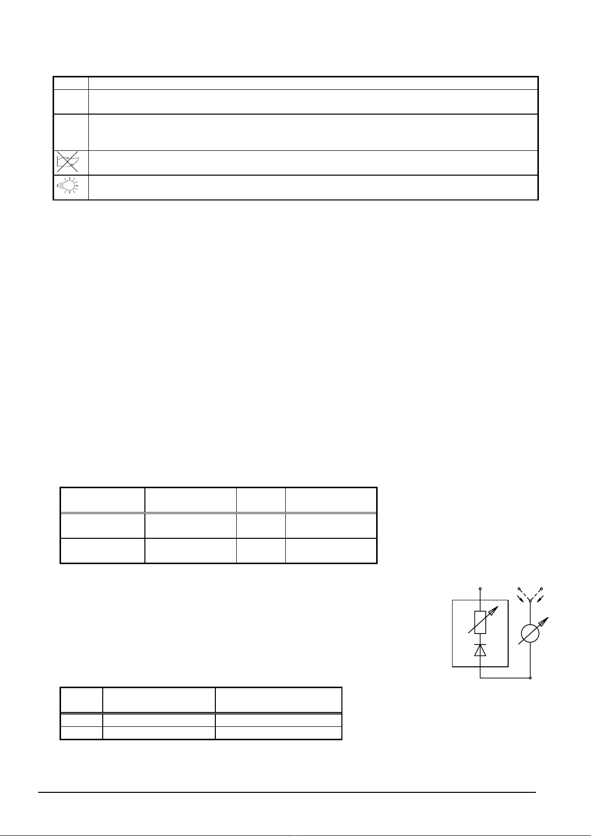
22 23 24
-
+
R
FL
I
QRA
7987a01/0999
I
Ion


