manuals.online logo
Brands
  1. Home
  2. •
  3. Brands
  4. •
  5. WEG
  6. •
  7. Industrial Electrical
  8. •
  9. WEG FHU ACW125 User manual

WEG FHU ACW125 User manual

#8-32 UNC
Tap
(4Holes)
4.212
(107)
1.18
(30)
0.433
(11)
4.251
(108) 4.685
(119) F
*Turn off the power before mounting, , wiring,
maintenance or inspection.
Failure to do may result in electric shocks and burns.
withdrawing
it
CAUTION
1. INSTALLATION INSTRUCTION
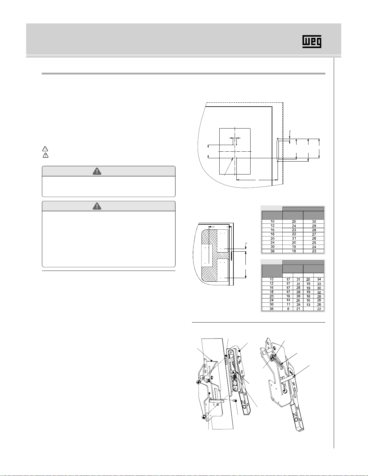
Figure. 1 and 2 show the location of the handle and door catch
when mounted on the enclosure.
FLANGE, OPERATING HANDLE (FHU ACW125)
2. HANDLE INSTALLATION-See Figures 3 and 4.
DANGER
TABLE1 MAXIMUM "E" DIMENSION
ENCLOSURE
DEPTH FHU-60 FHU-72
TABLE2 MAXIMUM " " DIMENSIONF
ENCLOSURE
DEPTH 62 cable 72 cable
<Fig. 2>
<Fig.3>
<Fig.1>
Dimensions: inch(mm)
Dimensions:inch
Dimensions:inch
1. Do not use deformed or damaged MCCB or operati handle.
2. Mounting, removal, wiring, maintenance and checking should
be done by authorized or certified .
3. Operati handle should not be used in severe environment
such as high temperature, humidity, dusty,corrosive gas and
excessive vibration.
4. Mounting should be done according to the instruction manual.
Mistakes on mounting may be a cause for a and
operation handle or cause an accident such as operator do
himself an injury.
ng
personnel
ng
ACW
1. Turn off and lock out all power supplying the circuit breaker and all
other equipment within the enclosure before installing.
2. Determine mounting location for the handle and circuit breaker. See
Figure. 1 and Tables 1 and 2.
3. The handle can be mounted on right side of flange type enclosures.
4. A latch is provided for applications where no interlocking door latch
mechanism is provided.
5. The PLATE ASS'Y BASE FH-1 mounts to the circuit breaker and
can be padlocked in the "OFF"position.
1. Secure O-RING into groove. Mount handle and frame to the
enclosure flange using the two M6X18 (+)PH, P/W screws. Tighten
screws to 75 in-lbs.
2. Place the PLATE FLANGE LINK onto the LINK CONNECTION PIN
and secure withthe E-ring, D8.
3. Attach the PLATE LOCK LINK to the PLATE LOCK FLANGE using the
M6X10 screw. Tighten nutsto25 in-lbs.
4. Close the enclosure door. This should release the PLATE LOCK LINK
allowing the handle to beturned ON. If the handle cannotbe turned ON,
adjustPLATE HOOKLOCKdownwardin itsslotand repeat item 4.
5. Turn handle ON and attempt to open door. The PLATE LOCK LINK
should hold the door closed. If the door can be opened, readjust the
PLATE HOOK LOCK upwardin its slot. Repeatsteps 3 and 4to insure
that the door can notbe opened whenthe handleis in the ON position.
handle
E
Be sure to read the instruction manual and safety precautions before
use products.
This manual should be given to the person who use products and
maintain them. SAFETY PRECAUTIONS
Before installation, wiring, operation, maintenance or inspection of
the device, be sure to read the warning message carefully and
ensurance proper operation.
Please follow the instructions, they are very important.
In this instruction, level of danger is classified by
UP DOWN UP DOWN
¤
¤
¤
¤
*
NOTE : THE MINIMUM BEND RADIUS FOR THE CABLE IS THREE&
ONE-HALF(3-1/2)INCHES.
Prepare the mounting holes for the handle and circuit breaker
and remove burrs.
F "UP"
F "DOWN"
E MAX
PLATEFLANGELINK
PLATELOCK LINK
M6X18
SCREW
PLATEASS'Y
FLANGE
O-RING
HANDLEASS'YFLANGE
GROOVE
E-RING,D8
PLATELOCK FLANGE
M6X10 SCREW
PLATELOCK LINK
LINKCONNECTIONPIN
8
DANGER
CAUTION It may result in death or serious injury.
It may result in injury or physical damage.
Installation Instruction
3. BREAKER AND BREAKER OPERATOR INSTALLATION-See Figure. 5
1. Turn the circuit breaker ON.
2. Attach circuit breaker and PLATE ASS'Y,BASE FHU to the back
panel using four N .8-32 UNC screws as shown at Figure 5.
Tighten screws to 150 in-lbs.
O
3. Attach the PLATE FIXED CABLE TO PLATE ASS`Y BASE FH3
using M5x10 screw. Tighten screws to 25 in-lbs.
*DANGER- Confirmthat suppling power has been turned off.
*CAUTION-DON'T PUSH TRIP BUTTON WITHFINGERS.
4. CABLE INSTALLATION - See Figure. 6
1. Secure cable to PLATE ASS'Y FLANGE with HOLDER FLANGE
CABLE using M5X10 screws. Tighten screws to 75 in-lbs.
HOLDER FLANGE CABLE must interlock with groove in cable.
2. Move handle to OFF position and pull cable to it's maximum stroke
Shim cable connecting and attach into hole of LINK ASS'Y.
Secure with E-ring.
3. Attach end of cable to PLATE ASS'Y BASE FHU as described below.
NOTE: To ensure proper adjustment and to prevent possible damage to
the operator, Follow the remaining steps carefully.
4. Move the handle to it's maximum ON position.
5. Adjust the top cable mounting nut to M5 from start of cable thread as
shown in Detail A.
6. Insert end of the cable rod through the hole in the PLATE BAR TAB
And place the cable mounting threads into the slotted FIXED TAB
PLATE of the PLATE ASS'Y BASE FHU. Tight cable mounting nut
(M12) And adjustment nut (M12) until the cable is secured to the tab.
7. After install the mounting nut and adjustment nut. Handle is maximum
On position.
5. CABLE ADJUSTMENT
<Fig.4>
MANUAL INSTRUCTION FHU ACW125
1. Check that the circuit breaker turns OFF and ON by moving the
operating handle. If circuit breaker does not turn ON, loosen adjusting
nut and tight lower adj nut to PLATE BAR TAB.
Repeat if required.
2. Turn the circuit breaker ON and trip it by pushing the "trip" button (not
using your finger).
3. If the circuit breaker does not reset, loose the lower adj nut and tight
adjusting nut to PLATE BAR TAB.
Repeat if required.
*DANGER- Confirm that suppling power has been turned off.
*CAUTION-DON'T PUSH TRIP BUTTON WITH FINGERS.
<Fig.5>
<Fig.6>
Tap
N0.8-32 UNC
PLATE ASS'Y,
BASE FHU
NO.8-32 UNC 2A
Mounting Screw
Dimensions:inch(mm)
PLATEHOOK LOCK
1/4, NUT
ENCLOSURE
DOOR
1.
( )
71
43.6
1.
( )
48
37.6
1.
( )
16
29.7
1.
( )
12
28.4
7.48
190( )
1.988
50.5( )
1.1
28( )
2.36
60( )
0.09
2.3( )
2.598
66( )
1/4 in
2 Screws
2.32
59( )
3.72
94.6
(OFF)
( )
3.14
( )79.65
(ON)
1.72
43.6( )
2.7
68.6)(
<Detail.A>
PIN CABLE CONNECTING
E-RING, D8
GROOVE
HOLDER FLANGE CABLE M ¿10 SCREW5
CABLE MOUNTING NUT
PLATEASS'Y
FLANGE
PLATE BAR TAB
ADJUSTING NUT,M5
CABLE ROD
FIXED TAB PLATE
ACW125-HOLE
LINKASS'Y
PLATE ASS'Y
BASE FHU
LOWER ADJ NUT

Other WEG Industrial Electrical manuals

WEG FHU ACW400 User manual

WEG

WEG FHU ACW400 User manual

WEG FSW 250 User manual

WEG

WEG FSW 250 User manual

WEG PFW03-M8 User manual

WEG

WEG PFW03-M8 User manual

WEG FSW 160 User manual

WEG

WEG FSW 160 User manual

WEG CWM Series Instruction manual

WEG

WEG CWM Series Instruction manual

WEG BFC0 User manual

WEG

WEG BFC0 User manual

WEG FSW 400 User manual

WEG

WEG FSW 400 User manual

WEG MPW100 User manual

WEG

WEG MPW100 User manual

WEG FSW 100 User manual

WEG

WEG FSW 100 User manual

WEG FSW 630 User manual

WEG

WEG FSW 630 User manual

WEG ACW100 User manual

WEG

WEG ACW100 User manual

WEG JC CWM9 105 Series User manual

WEG

WEG JC CWM9 105 Series User manual

WEG BCXML User manual

WEG

WEG BCXML User manual

WEG JC CWM9 105 Series User manual

WEG

WEG JC CWM9 105 Series User manual

WEG CWB Series User manual

WEG

WEG CWB Series User manual

WEG SCW100 Series User manual

WEG

WEG SCW100 Series User manual

WEG CWM Series User manual

WEG

WEG CWM Series User manual

Popular Industrial Electrical manuals by other brands

Eaton Power Defense PD-1 Series Instruction leaflet

Eaton

Eaton Power Defense PD-1 Series Instruction leaflet

Balluff BNI PNT-104-105-Z015 user guide

Balluff

Balluff BNI PNT-104-105-Z015 user guide

Murata GRM31C5C1H683JA01 Series Reference sheet

Murata

Murata GRM31C5C1H683JA01 Series Reference sheet

Murata GRT155C8YA224ME01 Series Reference sheet

Murata

Murata GRT155C8YA224ME01 Series Reference sheet

Murata GRM033C80J683ME15 Series Reference sheet

Murata

Murata GRM033C80J683ME15 Series Reference sheet

Fujitec VIS SETTER MK-3020 instruction manual

Fujitec

Fujitec VIS SETTER MK-3020 instruction manual

Murata GRM216R71H392KA01 Series Reference sheet

Murata

Murata GRM216R71H392KA01 Series Reference sheet

Allen-Bradley 140G-R-EP quick start guide

Allen-Bradley

Allen-Bradley 140G-R-EP quick start guide

Murata GRM0225C1A680JA02 Series Reference sheet

Murata

Murata GRM0225C1A680JA02 Series Reference sheet

Murata GRM0225C1E150JA03 Series Reference sheet

Murata

Murata GRM0225C1E150JA03 Series Reference sheet

Simco-Ion Simco-Ion MEB user manual

Simco-Ion

Simco-Ion Simco-Ion MEB user manual

Murata GQM2195C2E360GB12 Series Reference sheet

Murata

Murata GQM2195C2E360GB12 Series Reference sheet

Murata GCM219R71C204JA37 Series Reference sheet

Murata

Murata GCM219R71C204JA37 Series Reference sheet

Beckhoff EP1918 Operating	 instruction

Beckhoff

Beckhoff EP1918 Operating instruction

Grundfos CIU 202 Functional profile and user manual

Grundfos

Grundfos CIU 202 Functional profile and user manual

SCHUNK SPK Series operating manual

SCHUNK

SCHUNK SPK Series operating manual

ABB AF400 operating instructions

ABB

ABB AF400 operating instructions

Murata GRM188R60G476ME15 Series Reference sheet

Murata

Murata GRM188R60G476ME15 Series Reference sheet

manuals.online logo
manuals.online logoBrands
  • About & Mission
  • Contact us
  • Privacy Policy
  • Terms and Conditions

Copyright 2025 Manuals.Online. All Rights Reserved.