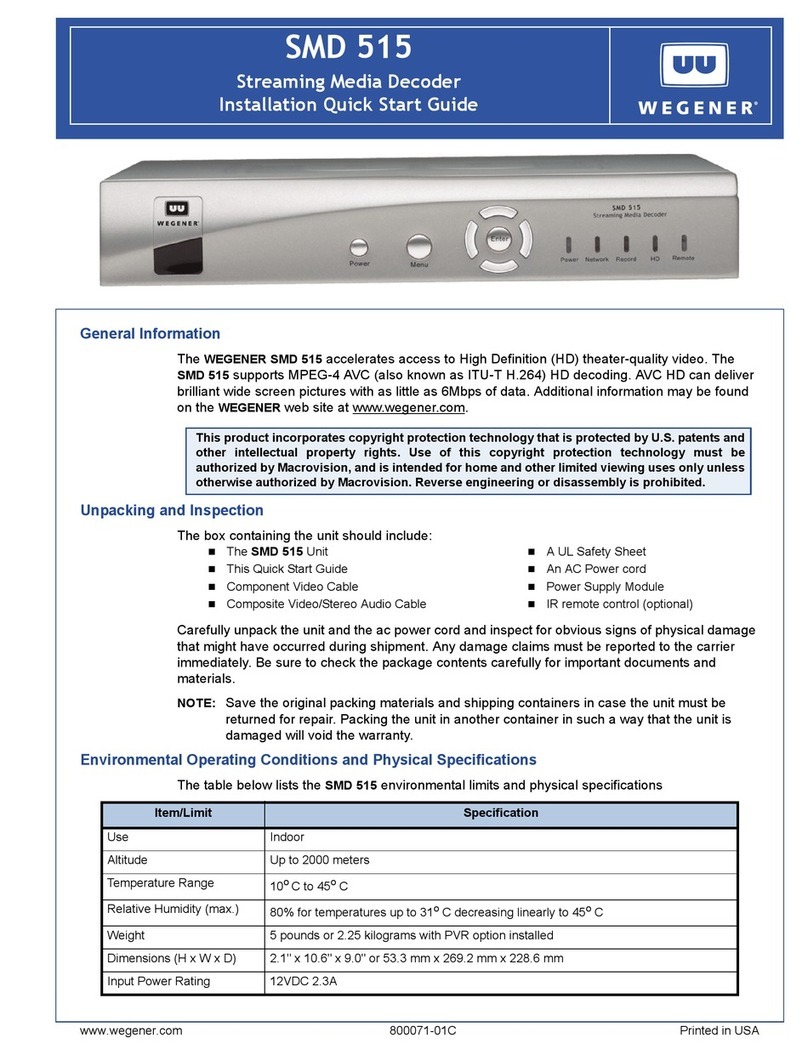
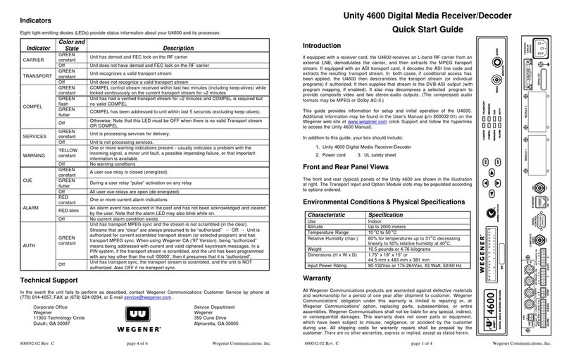
Wegener UNITY4000 User manual

WEGENER
COMMUNICATIONS R
TECHNOLOGY PARK / JOHNS CREEK
11350 TECHNOLOGY CIRCLE
DULUTH, GEORGIA 30097-1502
(770) 814-4000 FAX (770) 623-0698
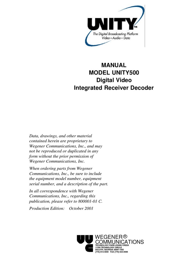
Instruction Manual
UNITY4000ª
AUDIO INTEGRATED
RECEIVER DECODER
D
ata, drawings, and other material
contained herein are proprietary to
Wegener Communications, Inc., and
may not be reproduced or duplicated in
any form without the prior permission
of Wegener Communications, Inc.
When ordering parts from Wegener
Communications, Inc., be sure to include
the equipment model number, equipment
s
erial number, and a description of the
p
art.
I
n all correspondence with Wegener
Communications, Inc., regarding this
p
ublication, please refer to UTY4000-
011A.
N
ote: Features of the product described
herein are covered by U.S. Patent #
4,985,895.
F
irst Edition: September 1999

Page 2
UTY4000-011 Page 2 of 75
This Page Intentionally Left Blank

Page 3
Page 3 of 77 UTY4000-003
CAUTION
RISK OF ELECTRIC SHOCK
DO NOT OPEN
CAUTION: TO REDUCE THE RISK OF ELECTRIC SHOCK,
DO NOT REMOVE COVER (OR BACK).
NO USER-SERVICEABLE PARTS INSIDE.
REFER SERVICING TO QUALIFIED SERVICE PERSONNEL.
CAUTION
As this unit is intended to interface with other electrical/electronic systems, proper
engineering practices must be adhered to during installation and check-out.
All AC power and ground must be installed in accordance with National Electric
Code Standards as to conductor size and limitations (see NFPA 70, articles 200-
280, as amended, if required), and lightning protection must be provided.
All RF interconnections must be properly shielded to prevent ingression or
egression of potential interfering sources to existing services.
Any damage to this unit caused by improper wiring/interconnections will void any
warranty extended.
The following warranty applies to all Wegener Communications products.
All Wegener Communications products are warranted against defective materials and workmanship for
a period of one year after shipment to customer. Wegener Communications' obligation under this
warranty is limited to repairing or, at Wegener Communications' option, replacing parts, subassemblies,
or entire assemblies. Wegener Communications shall not be liable for any special, indirect, or
consequential damages. This warranty does not cover parts or equipment which have been subject to
misuse, negligence, or accident by the customer during use. All shipping costs for warranty repairs will
be prepaid by the customer. There are no other warranties, express or implied, except as stated
herein.
WARRANTY

Page 4
UTY4000-011 Page 4 of 75
This Page Intentionally Left Blank

Page 5
Page 5 of 77 UTY4000-003
TABLE OF CONTENTS
SECTION 1 GENERAL INFORMATION...................................................................10
1.1 GENERAL ........................................................................................................................10
1.2 INTRODUCTION ..........................................................................................................10
1.3 UNPACKING AND INSPECTION...............................................................................10
1.4 PHYSICAL ENVIRONMENT .......................................................................................10
1.5 SECURITY LABELS ......................................................................................................11
1.6 PHYSICAL SPECIFICATIONS ...................................................................................11
1.7 TECHNICAL SUPPORT ...............................................................................................11
1.8 MANUALS.......................................................................................................................12
SECTION 2 SYSTEM CONFIGURATION ...............................................................14
2.1 UNIT OVERVIEW...........................................................................................................14
2.2 BLOCK DIAGRAM DISCUSSION .............................................................................14
2.3 SPECIFICATIONS ........................................................................................................16
2.3.1 L-BAND TUNER ..........................................................................................................16
2.3.2 QPSK DEMODULATOR ...............................................................................................17
2.3.3 TRANSPORT DEMUX.................................................................................................17
2.3.4 SYSTEM PROCESSOR ....................................................................................................17
2.3.5 AUXILIARY DATA PROCESSING ...................................................................................17
2.3.6 COMPOSITE VIDEO ENCODER ......................................................................................17
2.3.7 VIDEO SPECIFICATIONS................................................................................................18
2.3.8 AUDIO SPECIFICATIONS...............................................................................................18
2.3.9 SERIAL ASYNC DATA, MONITOR AND CONTROL OF IRD ..........................................19
2.3.10 ENCRYPTION ...............................................................................................................20
2.3.11 TRANSPORT OUTPUT...................................................................................................20
2.3.12 OPTION MODULES FOR EXPANSION PORTS..................................................................20
2.3.13 AC POWER .................................................................................................................20
2.3.14 LNB DC POWER ........................................................................................................20
2.3.15 FOUR INPUT / ONE OUTPUT RF SWITCH (OPTIONAL)..................................................20
2.3.15.1 Description..........................................................................................................20
2.3.15.2 Electrical Characteristics......................................................................................21
2.4 LOCAL CONTROLS AND INDICATORS ................................................................21
2.4.1 FRONT PANEL .............................................................................................................21
2.4.1.1 Front Panel Display................................................................................................21
2.4.1.2 Front Panel Keypad................................................................................................21
2.4.1.3 Indicator LEDÕs ......................................................................................................21
2.4.2 REAR PANEL...............................................................................................................22
2.4.2.1 MODE Control DIP-Switches ...............................................................................22

Page 6
UTY4000-011 Page 6 of 75
2.4.2.2 Standard DVB Synchronous Interface....................................................................22
2.5 EXTERNAL INPUTS AND OUTPUTS ........................................................................23
2.5.1 BALANCED AUDIO OUTPUTS.......................................................................................23
2.5.2 FCC-MANDATED SUPPRESSION OF RADIATED EMISSIONS..........................................23
2.5.3 ALARM RELAY AND ADDRESSABLE CONTACT CLOSURES...........................................24
2.6 EXPANSION CARD CONFIGURATION ...................................................................27
2.6.1 BALANCED AUDIO EXPANSION CARD.........................................................................27
2.6.1.1 Audio Card Jumper Configuration..........................................................................27
2.6.1.2 Audio Card Label Instructions................................................................................27
2.6.2 SYNC OR ASI DATA CARD JUMPER CONFIGURATION ..............................28
SECTION 3 OPERATION.............................................................................................29
3.1 MODES OF OPERATION............................................................................................29
3.1.1 POWER UP..................................................................................................................29
3.1.2 BOOT FAIL ..................................................................................................................29
3.1.3 ALARM, WARNING, & NORMAL .................................................................................29
3.2 LED & ALARM / WARNING CONDITIONS .............................................................30
3.2.1 CARRIER (GREEN).......................................................................................................30
3.2.2 AGC (GREEN)............................................................................................................30
3.2.3 MPEG (GREEN).........................................................................................................30
3.2.4 CUE (GREEN)..............................................................................................................30
3.2.5 COMPELª (GREEN)................................................................................................30
3.2.6 AUTHORIZED (GREEN) ................................................................................................31
3.2.7 ALARM (RED) .............................................................................................................31
3.2.8 WARNING (AMBER).....................................................................................................32
3.3 RELAYS ...........................................................................................................................32
3.3.1 PULSE COMMAND FOR RELAY CLOSURES...................................................................33
3.4 PROGRAM SELECTION..............................................................................................33
3.4.1 DUPLICATING AUDIO SERVICE ....................................................................................34
3.5 AUDIO HANDLING .......................................................................................................34
3.6 UNIT CONTROL ...........................................................................................................35
3.6.1 COMPELª...............................................................................................................35
3.6.2 TERMINAL...................................................................................................................35
3.6.3 MODEM ......................................................................................................................35
3.6.4 DIP SWITCHES .............................................................................................................35
3.6.5 DISPLAY / PUSH BUTTONS...........................................................................................36
3.7 SERIAL PORTS..............................................................................................................36
3.7.1 PRINTER DEVICE HANDLING .......................................................................................37
3.7.2 AUX DATA DEVICE......................................................................................................37
3.8 RECEIVER FUNCTIONS ..............................................................................................37
3.8.1 PERMS, TEMPS, SEARCHING & SETTINGS ....................................................................37
3.8.2 SETTINGS TABLE (OR SEARCH TABLE).........................................................................39
3.8.3 SIGNAL QUALITY MONITORING ..................................................................................40

Page 7
Page 7 of 77 UTY4000-003
3.8.4 FREQUENCY TAGGING................................................................................................40
3.9 DISPLAY / PUSH BUTTONS.......................................................................................41
3.9.1 OVERVIEW...................................................................................................................41
3.9.1.1 LCD Menu Timeout...............................................................................................41
3.9.2 PUSH BUTTON FUNCTIONS...........................................................................................42
3.9.3 E-MAIL................................................................... ERROR! BOOKMARK NOT DEFINED.
APPENDIX A TERMINAL/MODEM COMMANDS...................................................50
A.1 STATUS COMMANDS ................................................................................................50
A.1.1 H [COMMAND].............................................................................................................50
A.1.2 R TYPE [PAGE]............................................................................................................51
A.2 CONTROL COMMANDS............................................................................................51
A.2.1 ABORT......................................................................................................................51
A.2.2 ADDS LOCATION SETTINGS.........................................................................................51
A.2.3 DELS LOCATION ..........................................................................................................51
A.2.4 CADD LOCATION ROUTE SERVICE ATTENUATION ..........................................................51
A.2.5 CSEL PORT LOCATION.................................................................................................52
A.2.6 MUTE [SOURCE][SOURCE].........................................................................................52
A.2.7 OH..............................................................................................................................52
A.2.8 PC DEVICE BAUD PARITY.............................................................................................52
A.2.9 PERM SETTINGS..........................................................................................................52
A.2.10 PERMCH LOCATION...................................................................................................53
A.2.11 PW PASSWORD............................................................................................................53
A.2.12 RE STATE [NUMBER]....................................................................................................53
A.2.13 SETAUDIO PORT ROUTE [PROGRAM] [ATTEN]...........................................................53
A.2.14 SETLNB LO_FREQ....................................................................................................53
A.2.15 SETTIMEOUT SOURCE TIME ....................................................................................53
A.2.16 SNR ALARM_LEVEL MARGIN_OFFSET .........................................................................54
A.2.17 TEMP SETTINGS TIME ................................................................................................54
A.2.18 TEMPCH LOCATION TIME...........................................................................................54
A.1.19 UNMUTE [SOURCE][SOURCE]...................................................................................54
APPENDIX B FRONT PANEL DISPLAY.....................................................................56
B.1 HOME SCREEN.............................................................................................................56
B.2 AUDIO SETTINGS........................................................................................................56
B.3 E-MAIL............................................................ERROR! BOOKMARK NOT DEFINED.
B.4 HARDWARE SETUP ......................................................................................................58
B.4.1 CURRENT SETTINGS .....................................................................................................58
B.4.2 CHANNEL SELECTION..................................................................................................59
B.4.3 EDIT CHANNEL............................................................................................................59
B.4.4 SNR ALARM THRESHOLD...........................................................................................59
B.4.5 SERIAL PORTS..............................................................................................................59
B.4.6 LNB LOS....................................................................................................................60

Page 8
UTY4000-011 Page 8 of 75
B.4.7 UNIT LABEL ................................................................................................................61
B.4.8 UNIT RESET.................................................................................................................61
B.5 STATUS REPORTS.......................................................................................................61
B.5.1 SETTINGS STATUS.........................................................................................................61
B.5.2 CARRIER STATUS .........................................................................................................62
B.5.3 MPEG STATUS ...........................................................................................................65
B.5.4 SETTINGS TABLE .........................................................................................................66
B.5.5 NC STATUS .................................................................................................................66
B.5.6 PARAMETER STATUS....................................................................................................68
B.5.7 PORT STATUS...............................................................................................................69
B.5.8 RELAY STATUS............................................................................................................70
B.6 VERSION ........................................................................................................................70
B.7 NAVIGATION HELP......................................................................................................71
APPENDIX C GLOSSARY OF TERMS ......................................................................74
LIST OF ILLUSTRATIONS
Figure 1. UNITY4000 Block Diagram ..........................................................................................15
Figure 2. Ferrite Bead Installation.................................................................................................25
Figure 3. UNITY4000 Front Panel ...............................................................................................26
Figure 4. UNITY4000 Rear Panel.................................................................................................26
LIST OF TABLES
Table 1. Physical Specifications....................................................................................................11
Table 2. Tuner Specifications........................................................................................................16
Table 3. QPSK Demodulator Requirements .................................................................................17
Table 4. Video Resolution Requirements......................................................................................17
Table 5. Video Specifications........................................................................................................18
Table 6. Audio Specifications .......................................................................................................18
Table 7. Serial ASYNC Port Requirements...................................................................................19
Table 8. Serial 1 and Serial 2 Port Pin-outs...................................................................................19
Table 9. RF Switch Characteristics...............................................................................................21
Table 10. Front Panel LEDÕs* ......................................................................................................21
Table 11. Standard DVB Synchronous Parallel Interface Pin-out.................................................22
Table 12. Input and Output Connectors.......................................................................................23
Table 13. LED and Alarm Conditions...........................................................................................30
Table 14. Relay Operation............................................................................................................32
Table 15. Audio Handling .............................................................................................................34
Table 16. Dip Switch Function.....................................................................................................35
Table 17. Serial Device Settings ....................................................................................................36
Table 18. Settings Parameters .......................................................................................................37

Page 9
Page 9 of 77 UTY4000-003
Table 19. Settings Types ..............................................................................................................39
Table 20. IRD Signal Quality........................................................................................................40
Table 21. Display Modes .............................................................................................................41
Table 22. Push Button Functions .................................................................................................42
Table 23. LC Display Menus .......................................................................................................44

Page 10
UTY4000-011 Page 10 of 75
SECTION 1
GENERAL INFORMATION
1.1 GENERAL
The purpose of this manual is to describe the proper installation and operation of the Wegener
Communications UNITY4000 MPEG Video Integrated Receiver Decoder.
1.2 INTRODUCTION
The UNITY 4000 IRD is an integrated receiver/decoder designed to receive SCPC or MCPC
DVB-compliant digital video signals transmitted by satellite. The input to the IRD is an L-band
(950-2150 MHz) RF signal which is processed to produce composite video, audio, E-mail
output, auxiliary data, and relay cueing signals. The IRD is fully network-controlled via the WCI
COMPELcontrol system.
The optional decryption feature for the IRD allows for use of WCI conditional access.
Authorization of each IRD is under network control.
In addition to network control, the IRD features a front-panel LCD interface for gathering local
status information. In addition, limited control of the IRD (if allowed by the COMPEL
network) may be implemented via serial port, connecting either to a local terminal (or via phone
modem) to a remote terminal.
The IRD has expansion ports for up to two add-in modules. Contact the Wegener Sales
Department about available options.
1.3 UNPACKING AND INSPECTION
Carefully unpack the unit and inspect it for obvious signs of physical damage that might have
occurred during shipment. Any damage claims must be reported to the carrier immediately. Be
sure to check the package contents carefully for important documents and materials.
1.4 PHYSICAL ENVIRONMENT
Mount the UNITY4000 IRD in a standard EIA 19-inch equipment rack located in a clean, dry
environment, and do not place unsupported equipment on the unit. Make sure that total rack
power consumption does not exceed the limits of the AC branch circuit, and that a reliable earth
safety ground is maintained. The unit will meet the full 10-40oC operating temperature
specification only if adequate clearance around vent-holes is provided. The units may be arranged

Page 11
Page 11 of 77 UTY4000-003
without empty space between them, as long as enough rack ventilation is provided to prevent
severe heat buildup. Please note the maximum per-unit power dissipation of 45 watts.
1.5 SECURITY LABELS
The UNITY4000 uses security labels over some of the screws. There are no user serviceable
components within the unit, and tampering with the security labels or opening the units will void
your warranty. If you have questions, contact Wegener's customer service department at the
address, phone, or fax numbers listed in Section 1.7 of this manual.
1.6 PHYSICAL SPECIFICATIONS
The operating temperature of the IRD is +10¡C to +40¡C in still air with unblocked side vents.
(The unit is fan-cooled.)
Table 1. Physical Specifications
Parameter Description
Size 19ÓW x 1.75ÓH x 13.75ÓD
Weight 10.5 Pounds
Operating Temperature +10¡C to +40¡C
Power Requirements 115VAC, 60Hz, 0.8A Typ., or 230VAC,
50Hz, 0.5A Typ.
1.7 TECHNICAL SUPPORT
In the event the unit fails to perform as described, contact Wegener Communications Customer
To return a product for service:
* * * WARNING * * *
When connecting cables to ÒFÓ type connectors apply a force of no more than
12 inch lb. (Finger tight). Avoid connecting adapters directly to ÒFÓ type
connectors. Use at minimum a 1-foot flexible extension cable between ÒFÓ
type connectors and adapters.

Page 12
UTY4000-011 Page 12 of 75
xx Obtain a Return Material Authorization (RMA) number by completing and faxing a copy
of the RMA Form [See APPENDIX D (Page 76)] to (770) 232-0621. You may E-mail
the same information instead to:
mailto:[email protected]
xx Plainly write the RMA number on the outside of the product shipping container.
NOTE: Writing the RMA number on the outside of the shipping container will
help us to return your equipment to you sooner. Thank you.
xx Return the product, freight prepaid, to the address below:
Service Department RMA# ________
Wegener Communications, Inc.
11350 Technology Circle
Duluth, GA 30097
NOTE: All returned material must be shipped freight prepaid. C.O.D.
shipments will not be accepted.
Please contact Customer Service at the number above if you have any questions regarding service
procedures.
1.8 MANUALS
If you have any suggestions concerning this, or any Wegener Manual, please E-mail them to
mailto:[email protected].If you would rather mail them, please do so to the address shown
below. Our preference is that you copy the page in question, mark it up, and fax or mail us the
copy. We do appreciate constructive criticism. The Fax number is (770) 497-0411.
Attn: Manuals
Wegener Communications, Inc.
11350 Technology Circle
Duluth, GA 30097

Page 13
Page 13 of 77 UTY4000-003
This Page Intentionally Left Blank

Page 14
UTY4000-011 Page 14 of 75
SECTION 2
SYSTEM CONFIGURATION
2.1 UNIT OVERVIEW
The UNITY 4000 IRD features several separate hardware components, including the DC
switching power supply, the main motherboard, an L-band DVB receiver, front-panel keypad
controller card, a front-panel LCD assembly, and the L-band RF switch. The DC switching
power supply provides all internal regulated DC power. The optional L-band RF switch is
installed in the Module 2 expansion slot, and provides network or (if allowed by the network)
local user selection of up to four separate RF feeds. The selected RF feed output is connected to
the DVB-compliant L-band receiver card. This card tunes and demodulates the input QPSK
carrier, and then applies two layers of error correction decoding. Its output is the original
(possibly encrypted) multiplex MPEG transport stream which was input to the uplink IF
modulator. This stream then feeds the main motherboard, which decrypts (if necessary) the
stream and then demultiplexes out the selected video and audio elemental streams. These are, in
turn, de-compressed and converted back to the original analog source material for output.
Meanwhile, the user may query the IRD using the front-panel keypad for input and the LCD to
read the returned status information.
2.2 BLOCK DIAGRAM DISCUSSION
Refer to Figure 1, Page 15 for the following discussion.
The DVB-compliant receiver card demodulates the incoming QPSK carrier. It implements both
FEC decoding and de-interleaving per the DVB standard. The decoded byte stream is output to
the main board.
The input to the main board is the multiplexed MPEG2 transport stream. If encryption is active,
then the decryption function is executed. The resulting ÒclearÓ transport stream is then made
available for output on the TRANSPORT OUT connector at the rear of the unit. In parallel, that
stream is fed to the transport demultiplexer, this device selects the component elemental stream
for selected video and audio programs, as well as the network control data streams. The selected
video data is passed to an MPEG video decoder which converts the signal to linear digital video.
This is then converted to analog NTSC in a final encoder for output. Meanwhile, the selected
MPEG compressed audio stream is also routed to a combined decompression and digital-to-
analog converter IC. The output is one stereo pair of audio signals (L and R) on Channel 1 at the
back panel. In addition to the first stereo pair, a digital signal processor monitors and
demultiplexes out another selected digital audio stream, which is also decoded and output as the
stereo pair on Channel 2 at the back panel.

Page 15
Page 15 of 77 UTY4000-003
Figure 1. UNITY4000 Block Diagram
EXPANSION BUS CONNECTORS
CLOCK
27 Mhz
AUDIO
DEC 2
AUDIO
DEC 1
REG
REG
REG
20.000 MHZ
VCXO
27 Mhz Clock Distributions:
CHCLKA --> DVB Rcvr Module
20Mhz --> DSP_320C203
CHCLK (7.5 Mhz) Distributions:
CHCLKB --> CL9110
ECLK --> EXPM
CHCLKC --> XC5202
27M1A --> EXPA (Audio)
27M2 --> XC5204
27M3 --> 80C51XA
27M4 --> CPU_2096, TMS2490
27M5 --> DSP_2096
27M6 --> CS4920_1, CS4920_2
VCLK --> CD21
GCLK --> CD21
27M7 --> XC5202
27M1M --> EXPM (MPEG2)
DEMUX
VIDEO
ENCODER
LEFT
LEFT
RIGHT
RIGHT
COMPOSITE
CPU
FLASH 1
FLASH 2
Control Control
Addr/Data
DSP
DSP CTL
Address
Data
MPEG2 A/V
POWER
SUPPLY
120 VAC
SRAM
MPEG2
TRANSPORT
TRANSPORT
AUDIO 2
CONTACT
CLOSURE
DECRYPTION
I
2C BUS I
2C BUS I
2C BUSI
2C BUS
I
2C BUS
I
2C BUS
RED
GREEN
ALARM
RELAY
I/O PORT
R/X CONTROL
128K X 8
128K X 8
128K X 8
128K X 8
128K X 8
128K X 8
(32K X 8) (32K X 8)
CS
R/X CONTROL
R/X CONTROL
R/X DATA IN
FRAM
VIDEO DEC
256K X 16
256K X 16
256K X 16
256K X 16
256K X 16
256K X 16
DRAM
DRAM
SRAM
FLASH (DEBUG)
32K X 8
32K X 8 32K X 8
TX1
AUDIO
3 & 4
16
HS BUS
23
HBUS
I
2C BUS
IRQ / CTL
L_Addr
CLK_EN
RESET
5 & 6
SECURE MC
2048 X 8
DB9
RJ11
DB25
PLL
FIFO
DUART ALT. FRONT PANEL
MPEG2
RATE
BUFFER
TRANSPORT OUT MPEG2 AUDIO RF SWITCH FRONT PANEL
INT
POWER ON -
WATCHDOG
RESET
LNB
DVB RECEIVER
MODULE (OR
DECRYPTION
EXPANSION)
-12V
+5V
+24V
+5V
LNB
+3.3V
+3.3V
+12V
GND
+24V
+5V
DECRYPTION
EXPANSION
DB9
I/O PORT
LNB POWER
CONTROL
AUDIO 2
I
2C BUS
AUDIO OUT 2
AUDIO OUT 1
AES/EBU
J12
I
2C BUS
D1 VIDEO
J1
D1 OUT
A
C
D
A

Page 16
UTY4000-011 Page 16 of 75
The control system on the main board is run by the main host processor. This processor
interfaces with the COMPELª network as well as local users and then controls and monitors
the unitÕs operations. To do its job, this processor accesses the control data streams recovered
from the main transport demultiplexer. One of these may be a conditional access data stream (if
used). The main processor sends this data to a separate secure microprocessor, which looks to
see if its unit serial number is authorized to receive the broadcast signal and, if so, recovers the
secret keys for decrypting the incoming encrypted transport stream. Meanwhile, the main host
processor also communicates with several peripheral devices. It manages the data passed to/from
the front-panel keypad controller (which lights status LEDÕs, manages an LCD display, and
reads back keypresses). It manages the two serial ports which may be configured for printer,
terminal, modem, or auxiliary data output. It also controls the L-band receiver daughtercard and
any installed options modules (such as the RF switch).
For maximum flexibility, and to make value-added upgrades easily possible, the operating unit
software is stored in flash memory and may be dynamically replaced via the local serial port or
from the satellite network control channel.
2.3 SPECIFICATIONS
The receiver uses an integrated tuner and QPSK demodulator assembly.
2.3.1 L-Band Tuner
The tuner specifications are shown below.
Table 2. Tuner Specifications
Parameter Specification
Input Frequency Range 950 Ð 2150 MHz
Input Level Range -20 dBm total signal power down to Ð135
dBm/Hz signal power spectral density
Maximum Aggregate Input Power -5 dBm
Input Impedance 75 ohms, unbalanced
Input VSWR < 2.5:1
Input Noise Figure 8 Db MAX at minimum input level
L.O. Leakage at Input ≤-55 dBm

Page 17
Page 17 of 77 UTY4000-003
2.3.2 QPSK Demodulator
The QPSK demodulatorÕs input data rate is variable over the range shown in Table 3 (Page 17),
with a minimum transport-rate step size of 1 kbps. In Table 3, Òthreshold Eb/NoÓ is that value
of Eb/No at which the average number of uncorrected FEC frames exceeds one per minute.
Table 3. QPSK Demodulator Requirements
Inner Code Rate Symbol Rate Transport Rate Threshold Eb/No
_ 2.71-30 Msps 2.5-27.647 Mbps 4.0
2/3 2.04-30 Msps 2.5-36.863 Mbps 5.0
_ 1.81-30 Msps 2.5-41.471 Mbps 5.5
5/6 1.63-30 Msps 2.5-46.078 Mbps 6.0
7/8 1.55-30 Msps 2.5-48.382 Mbps 6.4
2.3.3 Transport DEMUX
The transport demux is used to extract the desired video and audio streams from the multiplexed
data stream.
2.3.4 System Processor
The main system processor is an extended architecture processor, and uses flash memory for
microcode storage with download capability via either terminal or satellite channel.
The unit also has an MPEG2 video processor ASIC, and an audio processor ASIC.
2.3.5 Auxiliary Data Processing
An asynchronous user-data stream embedded in the transport stream may be routed to SERIAL
1 or SERIAL 2 ports under user or network control. The controller need merely supply the PID
of the MPEG packets bearing the data and the output baud rate.
2.3.6 Composite Video Encoder
The IRD supports the video resolutions given in Table 4. The unit automatically senses the
format (NTSC or PAL) and reconfigures the video decompression system accordingly.
Table 4. Video Resolution Requirements
NTSC PAL
704H x 480V (Full Resolution) 704H x 576V

Page 18
UTY4000-011 Page 18 of 75
544H x 480V (3/4 Resolution) 544H x 576V
480H x 480V 480H x 576V
352H x 480V (1/2 Resolution) 352H x 576V
352H x 240V 352H x 288V
2.3.7 Video Specifications
NTSC video performance is specified below at a 9 Mbps video PES rate, maximum resolution.
Table 5. Video Specifications
Parameter Production Specification
Signal Type Composite
Output Level 1.0 Vp-p, ±2%
Output Impedance 75 Ohms
Multiburst NTSC (0.5 to 4.2 MHz) NTSC (0.5-4.2 MHz) ≤±0.5 Db
PAL (0.5-4.8 MHz) ≤±0.6 Db
Differential Gain ≤4 IRE
Differential Phase ≤1.5°
L/C Gain Inequality ≤±4 IRE
L/C Delay Inequality ≤±26 Ns
Line Time W-form Distortion ≤1 IRE p-p
Field Time W-form Distortion ≤3 IRE p-p
Video S/N Weighted ≥56 Db
2.3.8 Audio Specifications
Audio performance is specified below at a compressed-audio PES rate of 256 kbps.
Table 6. Audio Specifications
Parameter Specification (each channel of stereo
pair)
Output Level-MAX PPL +14.0 ±0.5 dBm into 600 ohms,
level at 0 Db audio attenuation
Impedance Balanced: < 60 Ohms
Frequency Response 20Hz to 20 kHz, + 0.5/-1.5 Db
50Hz to 15 kHz, ± 0.5 Db

Page 19
Page 19 of 77 UTY4000-003
Phase accuracy 50 Hz to 15 kHz, ≤± 2° from linear phase
Harmonic Distortion (1 kHz
test-tone, 1 Db below PPL) ≤0.5 %
S/N Ratio ≥80 Db (22 Hz to 20 KHz) unweighted
Dynamic Range 16 bits
A/V Sync ≤± 50 Ms error
2.3.9 Serial ASYNC Data, Monitor and Control of IRD
Two serial ports (SERIAL 1 and 2) for data to/from the IRD have the following characteristics:
Table 7. Serial ASYNC Port Requirements
Parameter Specification
Signal Type Serial Asynchronous Character Data
Levels RS-232
Mode Always 8 data-bits, one start, one stop-bit, half-duplex.
Pin-outs DCE to AT-compatible serial port, 3-wire subset (Rxd, Txd, and
Ground) without handshake lines. Connects directly to AT-compatible
PC 9-pin serial port, and requires null modem cable when connecting to
modem.
Table 8. Serial 1 and Serial 2 Port Pin-outs
SERIAL 1 SERIAL 2
Pin # Signal Pin # Signal
B1 DCD (Internally pulled high) A1 DCD (Internally pulled high)
B2 RXD (Output A2 RXD (Output)
B3 TXD (Input) A3 TXD (Input)
B4 DTR (Not connected) A4 DTR (Not connected)
B5 GNDS A5 GNDS
B6 DSA (Internally pulled high) A6 DSA (Internally pulled high)
B7 RTS (Not connected) A7 RTS (Not connected)
B8 CTS (Internally pulled high) A8 CTS (Internally pulled high)
B9 RI A9 RI

Page 20
UTY4000-011 Page 20 of 75
2.3.10 Encryption
The WCI decryption option includes a secure microprocessor and a decryption ASIC. Different
levels of security may be implemented with software and ASIC changes.
2.3.11 Transport Output
The TRANSPORT output supplies the original received MPEG2 transport stream in
Synchronous Parallel format.
2.3.12 Option Modules for Expansion Ports
The IRD has two expansion slots Ð one high speed and one low speed. The high speed
expansion port provides the transport layer multiplexed stream while the low speed expansion
port provides the filtered packet data. An I2C bus provides control for option modules. The
specifications for individual modules are included in documentation for the module.
2.3.13 AC Power
The unit features a universal-input power supply. AC line is fed into a standard IEC jack. The
nominal inputs are 115 or 230 VAC ± 10% at 50-60 Hz ± 2%. The total AC current
consumption with the 4:1 RF switch option and max LNB DC load is 0.8A at 115 VAC, and
0.5A at 230 VAC.
2.3.14 LNB DC Power
The unit may feed DC power to an external antenna-mounted LNB using either the RF-In
connectorÕs center-pin or a terminal on the rear-panel terminal strip (with an external DC power
inserter). The nominal voltage supplied is +17 to +24 VDC, while the maximum load current is
250 Ma. The output is short-circuit protected by a thermal fuse. A rear panel MODE DIP
switch may be used to activate/de-activate the DC output (See Section 2.4.2.1). An internal
jumper (J22) is used to enable/disable DC power on RF-In center-pin. (Therefore, to get DC
power on the RF-In center pin, both J22 and DIP switch must be set.)
2.3.15 Four Input / One Output RF Switch (Optional)
2.3.15.1 Description
The module is installed into the MODULE 2 option-slot position on the back of the parent IRD.
It allows the IRD to select one of four antenna / LNB inputs when its RF OUTPUT jack is
connected via a 75-ohm coax cable to the IRD RF INPUT. There is no power pass for LNB DC
power. (DC for the LNB is provided on the UTY4000 rear terminal strip and requires an
external DC power inserter. No DC voltage is applied to any F connector.) The input and
output RF connectors are Type-F jacks, and they are located on the option module rear panel.
Other manuals for UNITY4000
1
Table of contents
Other Wegener Media Converter manuals