Wegener iPUMP 6400 User manual

iPump 6400
Professional Media Server
User’s Manual
800009-01 Rev. J
iPump 6400
Professional Media Server

iPump 6400 User’s Manual
ii 800009-01 Rev. J www.wegener.com
Data, drawings, and other material contained herein are proprietary to Wegener
Communications, Inc., and may not be reproduced or duplicated in any form without the
prior written permission of Wegener Communications, Inc.
The information contained herein is subject to change without notice. Revisions may be
issued to advise of such changes and/or additions.
WEGENER!, COMPEL CONTROL!, MEDIAPLAN!, ENVOY, UNITY!, UNITY·IP!, and
iPUMP!are trademarks of Wegener Communications, Inc. All other trademarks are the
property of their respective owners.
"2007 Wegener Communications, Inc. All rights reserved.
Portions copyright 1992-2001 FairCom Corporation. "FairCom" and "c-tree plus" are
trademarks of FairCom Corporation and are registered in the United States and other
countries. All Rights Reserved.
Correspondence regarding this publication,
800009-01 Rev. J
Ninth Edition: August 2007
should be forwarded to:
Wegener Communications, Inc.
Technology Park/Johns Creek
11350 Technology Circle
Duluth, GA 30097-1502
Phone: 770-814-4000
Fax: 770-623-0698
The WEGENER iPump 6400 is approved under FCC Part 15B Class A, UL1950, CSA, and
CE.

www.wegener.com 800009-01 Rev. J iii
iPump 6400 User’s Manual
TABLE OF CONTENTS
LIST OF FIGURES . . . . . . . . . . . . . . . . . . . . . . . . . . . . . . . . . . . . . . . . . . . . . . . . . . . . . . . . . . . . . . . . VII
LIST OF TABLES . . . . . . . . . . . . . . . . . . . . . . . . . . . . . . . . . . . . . . . . . . . . . . . . . . . . . . . . . . . . . . . . IX
CHAPTER 1 GENERAL INFORMATION
1.1 Manual Overview . . . . . . . . . . . . . . . . . . . . . . . . . . . . . . . . . . . . . . . . . . . . . 1
1.2 iPump 6400 Overview . . . . . . . . . . . . . . . . . . . . . . . . . . . . . . . . . . . . . . . . . 1
Physical Description . . . . . . . . . . . . . . . . . . . . . . . . . . . . . . . . . . . . . . . . . . . . . . . . 2
Functional Description. . . . . . . . . . . . . . . . . . . . . . . . . . . . . . . . . . . . . . . . . . . . . . . 2
Status Monitoring . . . . . . . . . . . . . . . . . . . . . . . . . . . . . . . . . . . . . . . . . . . . . . . 2
Live Program Play. . . . . . . . . . . . . . . . . . . . . . . . . . . . . . . . . . . . . . . . . . . . . . . 2
Record Program to File. . . . . . . . . . . . . . . . . . . . . . . . . . . . . . . . . . . . . . . . . . . 2
Play Recorded Program File. . . . . . . . . . . . . . . . . . . . . . . . . . . . . . . . . . . . . . . 2
File Management . . . . . . . . . . . . . . . . . . . . . . . . . . . . . . . . . . . . . . . . . . . . . . . 2
Playlists. . . . . . . . . . . . . . . . . . . . . . . . . . . . . . . . . . . . . . . . . . . . . . . . . . . . . . . 2
Routing . . . . . . . . . . . . . . . . . . . . . . . . . . . . . . . . . . . . . . . . . . . . . . . . . . . . . . . 3
Stream Creation . . . . . . . . . . . . . . . . . . . . . . . . . . . . . . . . . . . . . . . . . . . . . . . . 3
Scheduled Operation . . . . . . . . . . . . . . . . . . . . . . . . . . . . . . . . . . . . . . . . . . . . 3
File Downloads . . . . . . . . . . . . . . . . . . . . . . . . . . . . . . . . . . . . . . . . . . . . . . . . . 3
Files Served to LAN . . . . . . . . . . . . . . . . . . . . . . . . . . . . . . . . . . . . . . . . . . . . . 4
Compel Control . . . . . . . . . . . . . . . . . . . . . . . . . . . . . . . . . . . . . . . . . . . . . . . . . 4
HTML Control . . . . . . . . . . . . . . . . . . . . . . . . . . . . . . . . . . . . . . . . . . . . . . . . . . 4
Contact Closure/Alarms . . . . . . . . . . . . . . . . . . . . . . . . . . . . . . . . . . . . . . . . . . 4
iPump 6400 Options . . . . . . . . . . . . . . . . . . . . . . . . . . . . . . . . . . . . . . . . . . . . . . . . 4
1.3 iPump 6400 Specifications . . . . . . . . . . . . . . . . . . . . . . . . . . . . . . . . . . . . . 6
Technical Specifications . . . . . . . . . . . . . . . . . . . . . . . . . . . . . . . . . . . . . . . . . . . . . 6
1.4 Safety Summary . . . . . . . . . . . . . . . . . . . . . . . . . . . . . . . . . . . . . . . . . . . . . 7
1.5 Glossary of Terms and Abbreviations . . . . . . . . . . . . . . . . . . . . . . . . . . . 8
CHAPTER 2 INSTALLATION
2.1 Unpacking and Inspection . . . . . . . . . . . . . . . . . . . . . . . . . . . . . . . . . . . . 11
2.2 Location and Mounting. . . . . . . . . . . . . . . . . . . . . . . . . . . . . . . . . . . . . . . 11
Precautions . . . . . . . . . . . . . . . . . . . . . . . . . . . . . . . . . . . . . . . . . . . . . . . . . . . . . . 11
Elevated Operating Ambient . . . . . . . . . . . . . . . . . . . . . . . . . . . . . . . . . . . . . . 11
Reduced Air Flow . . . . . . . . . . . . . . . . . . . . . . . . . . . . . . . . . . . . . . . . . . . . . . 11
Mechanical Loading . . . . . . . . . . . . . . . . . . . . . . . . . . . . . . . . . . . . . . . . . . . . 11
Circuit Overloading . . . . . . . . . . . . . . . . . . . . . . . . . . . . . . . . . . . . . . . . . . . . . 12

iv 800009-01 Rev. J www.wegener.com
Reliable Earthing . . . . . . . . . . . . . . . . . . . . . . . . . . . . . . . . . . . . . . . . . . . . . . . 12
Rack Installation Procedure . . . . . . . . . . . . . . . . . . . . . . . . . . . . . . . . . . . . . . . . . . 12
2.3 iPump 6400 Connections . . . . . . . . . . . . . . . . . . . . . . . . . . . . . . . . . . . . . 13
Alarm Connector Details . . . . . . . . . . . . . . . . . . . . . . . . . . . . . . . . . . . . . . . . . . . . 14
Ethernet/LAN Port Details . . . . . . . . . . . . . . . . . . . . . . . . . . . . . . . . . . . . . . . . . . . 15
Optional Decoder with Digital Output. . . . . . . . . . . . . . . . . . . . . . . . . . . . . . . . . . . 15
Pro Audio Decoder. . . . . . . . . . . . . . . . . . . . . . . . . . . . . . . . . . . . . . . . . . . . . . . . . 16
Multiswitch Connection Details . . . . . . . . . . . . . . . . . . . . . . . . . . . . . . . . . . . . . . . 17
CHAPTER 3 OPERATION
3.1 Operation Overview . . . . . . . . . . . . . . . . . . . . . . . . . . . . . . . . . . . . . . . . . 19
3.2 Front-panel Controls and Indicators . . . . . . . . . . . . . . . . . . . . . . . . . . . . 19
Liquid-Crystal Display (LCD) . . . . . . . . . . . . . . . . . . . . . . . . . . . . . . . . . . . . . . . . . 20
Push Buttons . . . . . . . . . . . . . . . . . . . . . . . . . . . . . . . . . . . . . . . . . . . . . . . . . . . . . 20
User Input Screens . . . . . . . . . . . . . . . . . . . . . . . . . . . . . . . . . . . . . . . . . . . . . . . . 20
Editable Data Fields . . . . . . . . . . . . . . . . . . . . . . . . . . . . . . . . . . . . . . . . . . . . 20
Editable Filename Field. . . . . . . . . . . . . . . . . . . . . . . . . . . . . . . . . . . . . . . . . . 21
Selectable Fields . . . . . . . . . . . . . . . . . . . . . . . . . . . . . . . . . . . . . . . . . . . . . . . 21
LED Indicators . . . . . . . . . . . . . . . . . . . . . . . . . . . . . . . . . . . . . . . . . . . . . . . . . . . . 21
3.3 Startup/Shutdown Procedures. . . . . . . . . . . . . . . . . . . . . . . . . . . . . . . . . 23
Initial Startup . . . . . . . . . . . . . . . . . . . . . . . . . . . . . . . . . . . . . . . . . . . . . . . . . . . . . 23
Normal Shutdown . . . . . . . . . . . . . . . . . . . . . . . . . . . . . . . . . . . . . . . . . . . . . . . . . 23
Normal Startup. . . . . . . . . . . . . . . . . . . . . . . . . . . . . . . . . . . . . . . . . . . . . . . . . . . . 23
Web Browser Operations Startup . . . . . . . . . . . . . . . . . . . . . . . . . . . . . . . . . . . . . 24
Static vs. dynamic setup . . . . . . . . . . . . . . . . . . . . . . . . . . . . . . . . . . . . . . . . . 24
Web Browser Access. . . . . . . . . . . . . . . . . . . . . . . . . . . . . . . . . . . . . . . . . . . . . . . 25
3.4 Front Panel Operation. . . . . . . . . . . . . . . . . . . . . . . . . . . . . . . . . . . . . . . . 26
LCD Menu Navigation . . . . . . . . . . . . . . . . . . . . . . . . . . . . . . . . . . . . . . . . . . . . . . 26
3.5 Front Panel Initial Unit Setup . . . . . . . . . . . . . . . . . . . . . . . . . . . . . . . . . . 26
Pre-configured Transport In Settings . . . . . . . . . . . . . . . . . . . . . . . . . . . . . . . . . . . 27
Navigation to Transport In Setup Screen. . . . . . . . . . . . . . . . . . . . . . . . . . . . . . . . 27
Transport In Current Channel Setup . . . . . . . . . . . . . . . . . . . . . . . . . . . . . . . . . . . 27
LNB Type . . . . . . . . . . . . . . . . . . . . . . . . . . . . . . . . . . . . . . . . . . . . . . . . . . . . . . . . 28
LNB DC Power Setting . . . . . . . . . . . . . . . . . . . . . . . . . . . . . . . . . . . . . . . . . . . . . 29
3.6 Front Panel Additional Unit Setup . . . . . . . . . . . . . . . . . . . . . . . . . . . . . . 30
Navigation to Date/Time Setup Screen . . . . . . . . . . . . . . . . . . . . . . . . . . . . . . . . . 30
Date/Time Setup . . . . . . . . . . . . . . . . . . . . . . . . . . . . . . . . . . . . . . . . . . . . . . . . . . 30
Navigation to Unit Label Setup Screen . . . . . . . . . . . . . . . . . . . . . . . . . . . . . . . . . 31
Unit Label Setup . . . . . . . . . . . . . . . . . . . . . . . . . . . . . . . . . . . . . . . . . . . . . . . . . . 31
Navigation to HTTP Proxy screens . . . . . . . . . . . . . . . . . . . . . . . . . . . . . . . . . . . . 32
HTTP Proxy IP and Port Setup . . . . . . . . . . . . . . . . . . . . . . . . . . . . . . . . . . . . . . . 32

www.wegener.com 800009-01 Rev. J v
iPump 6400 User’s Manual
Navigation to Return Path screen . . . . . . . . . . . . . . . . . . . . . . . . . . . . . . . . . . . . . 32
Return Path Setup . . . . . . . . . . . . . . . . . . . . . . . . . . . . . . . . . . . . . . . . . . . . . . . . . 33
3.7 Optional Front Panel Screens . . . . . . . . . . . . . . . . . . . . . . . . . . . . . . . . . 33
Navigation to Modem Setup Screen . . . . . . . . . . . . . . . . . . . . . . . . . . . . . . . . . . . 33
Modem Setup . . . . . . . . . . . . . . . . . . . . . . . . . . . . . . . . . . . . . . . . . . . . . . . . . . . . 34
Navigation to Genlock Setup Screen . . . . . . . . . . . . . . . . . . . . . . . . . . . . . . . . . . 35
Genlock Setup. . . . . . . . . . . . . . . . . . . . . . . . . . . . . . . . . . . . . . . . . . . . . . . . . . . . 35
Navigation to SMB Screen . . . . . . . . . . . . . . . . . . . . . . . . . . . . . . . . . . . . . . . . . . 35
SMB Screen Setup . . . . . . . . . . . . . . . . . . . . . . . . . . . . . . . . . . . . . . . . . . . . . . . . 36
Screen Park Setup . . . . . . . . . . . . . . . . . . . . . . . . . . . . . . . . . . . . . . . . . . . . . . . . 36
3.8 Web Browser Initial Setup . . . . . . . . . . . . . . . . . . . . . . . . . . . . . . . . . . . . 36
Access the Setup Tab . . . . . . . . . . . . . . . . . . . . . . . . . . . . . . . . . . . . . . . . . . . . . . 36
Decoder Setup . . . . . . . . . . . . . . . . . . . . . . . . . . . . . . . . . . . . . . . . . . . . . . . . . . . 37
Genlock Setup. . . . . . . . . . . . . . . . . . . . . . . . . . . . . . . . . . . . . . . . . . . . . . . . . . . . 38
User State vs. Current State . . . . . . . . . . . . . . . . . . . . . . . . . . . . . . . . . . . . . . 39
Satellite Receive Setup . . . . . . . . . . . . . . . . . . . . . . . . . . . . . . . . . . . . . . . . . . . . . 39
IP Setup. . . . . . . . . . . . . . . . . . . . . . . . . . . . . . . . . . . . . . . . . . . . . . . . . . . . . . . . . 39
LNB Setup . . . . . . . . . . . . . . . . . . . . . . . . . . . . . . . . . . . . . . . . . . . . . . . . . . . . . . . 40
SNR Alarm Warnings Setup . . . . . . . . . . . . . . . . . . . . . . . . . . . . . . . . . . . . . . . . . 41
Date / Time Setup . . . . . . . . . . . . . . . . . . . . . . . . . . . . . . . . . . . . . . . . . . . . . . . . . 41
Modem Setup . . . . . . . . . . . . . . . . . . . . . . . . . . . . . . . . . . . . . . . . . . . . . . . . . . . . 42
Network Setup. . . . . . . . . . . . . . . . . . . . . . . . . . . . . . . . . . . . . . . . . . . . . . . . . . . . 42
Return Path Setup . . . . . . . . . . . . . . . . . . . . . . . . . . . . . . . . . . . . . . . . . . . . . . . . . 43
iPump 615 Setup. . . . . . . . . . . . . . . . . . . . . . . . . . . . . . . . . . . . . . . . . . . . . . . . . . 43
3.9 iPump 6400 Operations by Function . . . . . . . . . . . . . . . . . . . . . . . . . . . . 43
Monitor iPump 6400 Status . . . . . . . . . . . . . . . . . . . . . . . . . . . . . . . . . . . . . . . . . . 43
Monitor Alarm and Warnings . . . . . . . . . . . . . . . . . . . . . . . . . . . . . . . . . . . . . . . . . 44
Live Program Play . . . . . . . . . . . . . . . . . . . . . . . . . . . . . . . . . . . . . . . . . . . . . . . . . 44
Checklist for Live Program Play . . . . . . . . . . . . . . . . . . . . . . . . . . . . . . . . . . . 44
Procedure for Live Program Play . . . . . . . . . . . . . . . . . . . . . . . . . . . . . . . . . . 45
Record Program to File . . . . . . . . . . . . . . . . . . . . . . . . . . . . . . . . . . . . . . . . . . . . . 46
Procedure for Recording a Program to File . . . . . . . . . . . . . . . . . . . . . . . . . . 46
Play Recorded Program File . . . . . . . . . . . . . . . . . . . . . . . . . . . . . . . . . . . . . . . . . 48
File Management. . . . . . . . . . . . . . . . . . . . . . . . . . . . . . . . . . . . . . . . . . . . . . . . . . 49
File Streaming and Routing. . . . . . . . . . . . . . . . . . . . . . . . . . . . . . . . . . . . . . . . . . 51
Scheduled Operation. . . . . . . . . . . . . . . . . . . . . . . . . . . . . . . . . . . . . . . . . . . . . . . 51
Playlist Management . . . . . . . . . . . . . . . . . . . . . . . . . . . . . . . . . . . . . . . . . . . . . . . 52
About Playlists . . . . . . . . . . . . . . . . . . . . . . . . . . . . . . . . . . . . . . . . . . . . . . . . 53
Playlist styles. . . . . . . . . . . . . . . . . . . . . . . . . . . . . . . . . . . . . . . . . . . . . . 53
Looping Styles. . . . . . . . . . . . . . . . . . . . . . . . . . . . . . . . . . . . . . . . . . . . . 54
Random and sequential tags . . . . . . . . . . . . . . . . . . . . . . . . . . . . . . . . . 54
Playlist Procedures . . . . . . . . . . . . . . . . . . . . . . . . . . . . . . . . . . . . . . . . . . . . . . . . 54
Procedures for opening, creating, saving, and deleting playlists . . . . . . . . . . 54
Opening a playlist . . . . . . . . . . . . . . . . . . . . . . . . . . . . . . . . . . . . . . . . . . 54
Creating a playlist . . . . . . . . . . . . . . . . . . . . . . . . . . . . . . . . . . . . . . . . . . 54

vi 800009-01 Rev. J www.wegener.com
Saving a playlist. . . . . . . . . . . . . . . . . . . . . . . . . . . . . . . . . . . . . . . . . . . . 55
Deleting a playlist. . . . . . . . . . . . . . . . . . . . . . . . . . . . . . . . . . . . . . . . . . . 55
Procedures for editing playlists . . . . . . . . . . . . . . . . . . . . . . . . . . . . . . . . . . . . 55
Navigating the Asset List . . . . . . . . . . . . . . . . . . . . . . . . . . . . . . . . . . . . . 55
Adding items to a playlist . . . . . . . . . . . . . . . . . . . . . . . . . . . . . . . . . . . . . 55
Deleting items from a playlist. . . . . . . . . . . . . . . . . . . . . . . . . . . . . . . . . . 56
Moving items in a playlist. . . . . . . . . . . . . . . . . . . . . . . . . . . . . . . . . . . . . 56
Navigating large playlists. . . . . . . . . . . . . . . . . . . . . . . . . . . . . . . . . . . . . . . . . 56
Playlist pages. . . . . . . . . . . . . . . . . . . . . . . . . . . . . . . . . . . . . . . . . . . . . . 56
Procedures for customizing playlists . . . . . . . . . . . . . . . . . . . . . . . . . . . . . . . . 57
Editing the Description. . . . . . . . . . . . . . . . . . . . . . . . . . . . . . . . . . . . . . . 57
Creating and deleting Aliases . . . . . . . . . . . . . . . . . . . . . . . . . . . . . . . . . 57
Adding on-screen graphics . . . . . . . . . . . . . . . . . . . . . . . . . . . . . . . . . . . 58
Setting a start time for a playlist. . . . . . . . . . . . . . . . . . . . . . . . . . . . . . . . 59
iPump 6400 Help . . . . . . . . . . . . . . . . . . . . . . . . . . . . . . . . . . . . . . . . . . . . . . . . . . 60
3.10 Unit Software Switch. . . . . . . . . . . . . . . . . . . . . . . . . . . . . . . . . . . . . . . . 60
Software Switch Procedure . . . . . . . . . . . . . . . . . . . . . . . . . . . . . . . . . . . . . . . . . . 60
Verify Software Version Procedure . . . . . . . . . . . . . . . . . . . . . . . . . . . . . . . . . . . . 61
CHAPTER 4 MAINTENANCE AND TROUBLESHOOTING
4.1 Maintenance. . . . . . . . . . . . . . . . . . . . . . . . . . . . . . . . . . . . . . . . . . . . . . . . 63
4.2 Troubleshooting . . . . . . . . . . . . . . . . . . . . . . . . . . . . . . . . . . . . . . . . . . . . 63
No Functions At All . . . . . . . . . . . . . . . . . . . . . . . . . . . . . . . . . . . . . . . . . . . . . . . . 63
No Output. . . . . . . . . . . . . . . . . . . . . . . . . . . . . . . . . . . . . . . . . . . . . . . . . . . . . . . . 63
Trouble Using Browser Interface . . . . . . . . . . . . . . . . . . . . . . . . . . . . . . . . . . . . . . 63
LED Indicators . . . . . . . . . . . . . . . . . . . . . . . . . . . . . . . . . . . . . . . . . . . . . . . . . . . . 64
Fault (Alarm/Warning) Indications . . . . . . . . . . . . . . . . . . . . . . . . . . . . . . . . . . . . . 65
CHAPTER 5 CUSTOMER SERVICE
5.1 Warranty. . . . . . . . . . . . . . . . . . . . . . . . . . . . . . . . . . . . . . . . . . . . . . . . . . . 67
5.2 Technical Support . . . . . . . . . . . . . . . . . . . . . . . . . . . . . . . . . . . . . . . . . . . 67
INDEX . . . . . . . . . . . . . . . . . . . . . . . . . . . . . . . . . . . . . . . . . . . . . . . . . . . . . . . . . . . . . . . . . . . . . . . . 69

www.wegener.com 800009-01 Rev. J vii
iPump 6400 User’s Manual
LIST OF FIGURES
Figure 1.1: iPump 6400 routing ....................................................................................3
Figure 2.1: Proper rack installation for iPump 6400 ..................................................12
Figure 2.2: iPump 6400 rear-panel connector locations ............................................13
Figure 2.3: Digital output decoder connector layout ...................................................15
Figure 2.4: Balanced analog and AES/EBU digital audio connector ..........................16
Figure 2.5: Connectors for the Pro Audio Decoder ...................................................17
Figure 2.6: Typical RF multiswitch .............................................................................17
Figure 3.1: iPump 6400 front panel ............................................................................19
Figure 3.2: iPump 6400 front panel push buttons ......................................................20
Figure 3.3: Editable data field ..................................................................................20
Figure 3.4: Editable filename field .............................................................................21
Figure 3.5: Selectable field .......................................................................................21
Figure 3.6: iPump 6400 front panel LED indicators. ..................................................21
Figure 3.7: iPump 6400 web browser control setup process ...................................24
Figure 3.8: iPump 6400 web browser Status tab ......................................................25
Figure 3.9: iPump 6400 LCD menu structure ............................................................26
Figure 3.10: LCD menu navigation to Transport In Setup screen ...............................27
Figure 3.11: Menu navigation to set Transport In Current Channel ............................28
Figure 3.12: Menu navigation to set LNB type ............................................................29
Figure 3.13: Menu navigation to set LNB DC power ...................................................29
Figure 3.14: LCD Menu navigation to Date/Time Setup screen ...................................30
Figure 3.15: LCD menu navigation to Set Unit Label screen .......................................31
Figure 3.16: LCD menu navigation to HTTP Proxy screens ........................................32
Figure 3.17: LCD menu navigation to Return Path screen ..........................................33
Figure 3.18: LCD menu navigation to Modem screen ..................................................34
Figure 3.19: LCD menu navigation to Genlock screen ................................................35
Figure 3.20: LCD menu navigation to SMB screen ......................................................35
Figure 3.21: iPump 6400 web browser Setup tab .....................................................37
Figure 3.22: iPump 6400 web browser Status tab ......................................................44
Figure 3.23: iPump 6400 web browser Rec/Play tab ...................................................47
Figure 3.24: iPump 6400 web browser Files tab ..........................................................50
Figure 3.25: iPump 6400 web browser Streams tab ....................................................51
Figure 3.26: iPump 6400 web browser Schedule tab ..................................................52
Figure 3.27: iPump 6400 web browser Playlist tab ....................................................53

iPump 6400 User’s Manual
viii 800009-01 Rev. J www.wegener.com
Figure 3.28: Large Playlist Navigation tools .................................................................57
Figure 3.29: iPump 6400 web browser Help tab ..........................................................60
Figure 3.30: Menu navigation to switch unit software .................................................60
Figure 3.31: Menu navigation to Version Info ..............................................................61

www.wegener.com 800009-01 Rev. J ix
iPump 6400 User’s Manual
LIST OF TABLES
Table 1.1: iPump 6400 options key ............................................................................4
Table 1.2: iPump 6400 technical specifications i ........................................................6
Table 1.3: Glossary of terms and abbreviations .........................................................8
Table 2.1: iPump 6400 connector details ..................................................................14
Table 2.2: iPump 6400 Alarm connector pin functions ............................................15
Table 2.3: iPump 6400 LAN connector pin functions ................................................15
Table 2.4: Digital output decoder connectors ........................................................16
Table 2.5: Balanced analog and AES/EBU digital audio connector pin functions ....16
Table 2.6: RF port selection signals .........................................................................17
Table 3.1: iPump 6400 front panel LED indicator descriptions .................................22
Table 3.2: iPump 6400 web browser control setup procedure ..................................24
Table 3.3: iPump 6400 pre-configured Transport In Settings ...................................27
Table 3.4: Menu navigation to Transport In Setup screen ........................................27
Table 3.5: Procedure for adjusting Transport In Current Channel settings ...............28
Table 3.6: Procedure for setting LNB LO Frequencys .............................................29
Table 3.7: Procedure for setting LNB DC power .......................................................29
Table 3.8: Procedure for setting Date/Time parameters ...........................................30
Table 3.9: Procedure for entering iPump 6400 Unit Label ........................................31
Table 3.10: Procedure for adjusting HTTP Proxy settings ..........................................32
Table 3.11: DVB programs ........................................................................................45
Table 3.12: Large Playlist Navigation .........................................................................57
Table 3.13: Procedure for switching iPump 6400 software version ............................61
Table 4.1: iPump 6400 LED indicator descriptions ...................................................64

iPump 6400 User’s Manual
x 800009-01 Rev. J www.wegener.com

www.wegener.com 800009-01 Rev. J 1
iPump 6400 User’s Manual
CHAPTER 1 GENERAL INFORMATION
1.1 Manual Overview
This manual provides instructions and reference information for the proper installation and
operation of the WEGENER iPump 6400 Professional Media Server, referred to throughout
the manual as the iPump 6400.
This manual is divided into these chapters:
Chapter 1 General Information -a description of the iPump 6400, its functions and
specifications, and a glossary of terms.
Chapter 2 Installation - procedures and information for the correct and safe installation
of the iPump 6400.
Chapter 3 Operation- instructions on starting and operating the iPump 6400.
Chapter 4 Maintenance and Troubleshooting - information on maintaining the
iPump 6400 and resolving possible operating difficulties.
Chapter 5 Customer Service - our warranty and information on obtaining help.
Index - list of keywords to help you quickly locate information.
Please e-mail any suggestions or comments concerning this manual to
manuals@wegener.com. If you prefer to post through the mail, please send your comments
to the address below. If you have substantial or complex changes to recommend, our
preference is that you copy the page(s) in question, mark your changes on that copy, and
fax or mail us the copy. We always appreciate constructive criticism.
Our Address:
1.2 iPump 6400 Overview
The WEGENER iPump 6400 is an integrated, digital satellite receiver, decoder, and media
server designed to provide the most cost effective method of delivering and storing digital
content for broadcast, cable, and business operations. The iPump 6400 is a key part of the
Wegener Communications Digital Media Delivery System which combines secure MPEG
and IP digital transmission with media management and server storage. At a given time, up
to 260 hours of media content can be stored on a single iPump 6400 (with optional, large
disk capacity) and served out via Ethernet according to current need or predetermined
schedules.
With the iPump 6400, you can receive, decode, and play out broadcast-quality
transmissions while at the same time receiving from satellite and recording multiple
Attn: Manuals
Wegener Communications, Inc.
Technology Park / Johns Creek
11350 Technology Circle
Duluth, GA 30097-1502
Our fax number:(770) 497-0411

General Information
2 800009-01 Rev. J www.wegener.com
programs or IP data files. Combined with our Compel MediaPlan software, the iPump 6400
can also place spot segments into real-time or recorded programs and can schedule
playback of custom sequences of live and recorded content.
Physical
Description
The iPump 6400 is housed in a standard, 2 RU, rack-mountable chassis. Its front panel
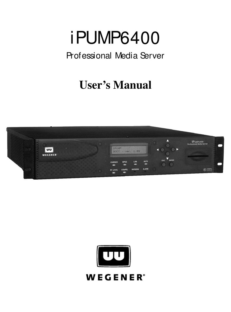
provides a user interface through an LCD and six push buttons (see Figure 3.1: iPump 6400
front panel on page 19). The rear panel holds the power switch and the ports that allow
connection to power, incoming signal, and peripheral devices.
Functional
Description
The iPump 6400 can perform the following functions:
Status Monitoring
Front-panel and web browser interface screens allow real-time monitoring of iPump 6400
activity, settings, and signal characteristics.
Live Program Play
The iPump 6400 decodes an incoming DVB MPEG program from the received satellite
signal. It decrypts and decodes the audio and/or video from the selected program through
analog or digital output ports to your monitor or transmission equipment. The incoming
content may be either a "classical" DVB program or an IP multicast stream. RF and decoder
settings are selected by the user. Two live programs from the same DVB carrier may be
played simultaneously by iPump 6400s that have the optional second decoder.
Record Program to File
The iPump 6400 can simultaneously record up to three separate multiplexed programs
(either "classical" DVB or IP multicast stream) from the incoming stream including any that
are played live to the decoder(s). The user selects the programs and enters a file name,
audio setting, and a recording time (duration) for each. Files are recorded to disk in the
iPump 6400 for later play-out or downloading. Up to 40 GB of storage (up to 43.3 hours of
programming depending on data rate) is available on standard iPump 6400s and up to 240
GB on optional, extended-storage iPump 6400s (see Disk Storage Capacity on page 5).
Record and play functions can be used in such applications as "tape delay"/time zone
shifting, "spot" localization of commercials, and corporate training media distribution.
Play Recorded Program File
The iPump 6400 plays out the selected, stored program files to the connected audio and
video monitors. File playing may be initiated by a predetermined schedule via Compel or by
a schedule stored internally to the iPump 6400. The user may also command playing of files
directly from a web browser or from the front panel. Two recorded programs (or one
recorded and one live) may be played simultaneously on iPump 6400s with an optional
second decoder.
File Management
Compel users can rename or delete files stored on the iPump 6400 and organize them into
directories or folders. Renaming and deleting files may also be performed through a web
browser connected to the iPump 6400 over a LAN.
Playlists
Sequences of programs called playlists can be created and stored on the iPump 6400 by
the user (locally or by Compel). Up to 2,000 playlists can be stored in nonvolatile memory
and played back with no interruption between programs. Settings can be made to repeat the

www.wegener.com 800009-01 Rev. J 3
iPump 6400 User’s Manual
playlist indefinitely, complete the playlist and repeat only the last program indefinitely, or
complete the playlist and simply return the decoder to its previous state.
Routing
The iPump 6400 can serve as a satellite-to-LAN IP router. Both unicast and multicast IP
traffic is supported.
Multicast traffic can include, for example, MPEG video streaming data.
The IGMP protocol is followed for multicast traffic.
Stream Creation
The iPump 6400 can create IP multicast video streams and present them on the LAN for
use by other equipment. The source of the video stream may be either a prerecorded or
downloaded file or a "classical" DVB program.
The iPump 6400 can also multicast previously-stored streams to the LAN. See Figure 1.1:
iPump 6400 routing for an illustration of iPump 6400 routing paths.
Figure 1.1: iPump 6400 routing
Scheduled Operation
Schedules of record, play, and other operations for automatic execution by the iPump 6400
may be set up using the Compel network and may be viewed from the web browser
interface. (Schedule operations support wild cards and ranges in day, date, and time fields
for repetitive events.)
File Downloads
The iPump 6400 accepts files downloaded from the satellite link via Compel’s Assured File
Delivery package. Application software and other files may also be downloaded. Up to five
downloads may be performed simultaneously up to an aggregate data rate of 25 Mbps.
The iPump 6400's file download and record functions may be used to load the unit with
content for playout (according to a pre-arranged schedule if desired) at any time. This can

General Information
4 800009-01 Rev. J www.wegener.com
be particularly useful in applications with extended or continuous playout needs and limited
satellite operating times.
Files Served to LAN
Users sharing a LAN with the iPump 6400 may download stored files from the iPump 6400
to their local workstation or server using FTP or SMB protocol.
Compel Control
iPump 6400 operation may be controlled remotely by a Compel network. Compel
Conditional Access controls which iPump 6400s may access the satellite’s material and
prevents access by any other receive equipment. Local control of the unit may be disabled
for exclusive control by Compel. The iPump 6400 always follows the most recent command
received and does not prioritize commands based on origination from the front panel, web
browser interface, or Compel network.
HTML Control
Control of the iPump 6400 is available from any web browser on the LAN to which it is
connected or via the internet if desired. The IP address and subnet mask can be displayed
and changed at the iPump 6400 front panel.
Contact Closure/Alarms
The iPump 6400 provides a contact closure through a rear-panel connector whenever the
unit enters an alarm condition. An additional user relay is also available. The iPump 6400
can also sense a contact closure input. Using Compel, file playouts can be triggered by
local closure of this input.
iPump 6400
Options
The iPump 6400 Professional Media Server is available in several configurations to meet
specific applications. Input type, decoder type, disk storage capacity, Conditional Access,
and the presence of a second decoder can be varied to create models best suited for your
specific needs.
The iPump 6400 model number is structured as follows to describe the options on each
iPump 6400: IP - ABC - D - EF - G - HH - JKK
Table 1.1 lists the options in each equipment category.
Table 1.1: iPump 6400 options key
Model Number
Position Option Name Designator Description
IP This prefix simply indicates that the unit is an iPump.
AFirst Decoder Type
(top slot)
0 - No decoder
1 - Basic decoder
2 - professional 4:2:0 decoder with analog outputs
3 - professional 4:2:2 decoder with analog outputs
4 - professional 4:2:2 decoder with digital outputs
5 - professional audio output
6 - professional 4:2:0 decoder with analog outputs
and channel 3-4 modulator connector

www.wegener.com 800009-01 Rev. J 5
iPump 6400 User’s Manual
BSecond Decoder Type
(middle slot)
0 - No second decoder
1 - Basic decoder
2 - professional 4:2:0 decoder with analog outputs
3 - professional 4:2:2 decoder with analog outputs
4 - professional 4:2:2 decoder with digital outputs
5 - professional audio output
6 - professional 4:2:0 decoder with analog outputs
and channel 3-4 modulator connector
CInput Type
(bottom slot)
1 - DVB RF Input
2 - ASI Input
DDisk Storage Capacity 1 - 40 Gigabytes
2 - 80 Gigabytes
3 - 120 Gigabytes
4 - 160 Gigabytes
5 - 200 Gigabytes
6 - 240 Gigabytes
EContact Closure Module
Type
1 - Alarm and contact closure in and out on DB-9
2 - Alarm and contact closure in and out on DB-9,
plus RJ-11 internal modem
FChannel 3-4 Modulator 0 - none
1 - present
GReserved
HH Conditional Access Type
JLine Cord
(power connector)
1 - U.S.
2 - U.K.
3 - Europe
4 - Australia
KK Other 00 - none
01 - Aux Audio
02 - KenCast FEC
03 - KenCast FEC plus Aux Audio
04 - OSD
05 - OSD plus Aux Audio
06 - OSD plus KenCast FEC
07 - OSD plus KenCast FEC plus Aux Audio
Model Number
Position Option Name Designator Description

General Information
6 800009-01 Rev. J www.wegener.com
1.3 iPump 6400 Specifications
Technical
Specifications
Table 1.2: iPump 6400 technical specifications i
Characteristic Specification
RF
Input Frequency tuning via front panel control or Compel
Input FrequencyRange 950 to 2150 MHz
Input Impedance 75 ohms
LNB Power 250 mA max, 22 kHz tone control
vertical polarity: 12.4 to 14.0 VDC
horizontal polarity: 17.0 to 19.0 VDC
Tuning Resolution 1 kHz
Modulation QPSK
Transport Rate Range 2.0 to 45 Msps
Video Compression
Video Data Rate up to 15 Mbps per service
Compression Type MPEG 4:2:0 or 4:2:2
Horizontal Resolution 720, 704, 640, 544, 480, 352
Vertical Resolution 480 lines @ 30 Hz (NTSC)
240 lines @ 30 Hz (NTSC)
576 lines @ 25 Hz (PAL)
288 lines @ 25 Hz (PAL)
Video Output
Video Format NTSC/PAL composite and SDI (with embedded audio)
Output Level 1 Vpp ± 5%
Output Impedance 75 ohms
Audio Compression
Compression Type MPEG Layer II
Data Rate 64 to 384 kbps
Output Modes Supported Mono, Dual Mono, Joint Stereo
Audio Output
Frequency Response 20 Hz to 20 kHz

www.wegener.com 800009-01 Rev. J 7
iPump 6400 User’s Manual
1.4 Safety Summary
The iPump 6400 is designed for safe use with few special precautions required of the user.
The following items are basic precautions to use when installing and working with your
iPump 6400:
Do not open the iPump 6400's chassis cover.
General
Power Supply 100 to 120 V or 200 to 240 V (auto switches)
60/50 Hz
5.0/2.5 A
Size
weight ~20 pounds (9.1 kg)
height 3.5 inches (90 mm)
width 19 inches (483 mm)
[17 inches (432 mm) with mounting ears removed]
depth 16"(406 mm)
Environmental
Use Indoor only
Operating Temperature +10° C to +40° C
Altitude Less than 2000 meters
Humidity Maximum relative humidity of 80% for temperatures up
to 31° C decreasing linearly to 50% relative humidity at
40° C.
Characteristic Specification

General Information
8 800009-01 Rev. J www.wegener.com
1.5 Glossary of Terms and Abbreviations
Table 1.3: Glossary of terms and abbreviations
Term Definition
AC Alternating current
Alarm A condition or notification of a condition that prevents the iPump 6400 from performing properly.
AFD Assured File Delivery.
Authorized Describes an iPump 6400 which has the ability through Compel Conditional Access to
decrypt programs encrypted by the Compel software.
Carrier An RF signal containing coded audio, video, and/or other data.
Compel!WEGENER's network control software that may be used to manage a number of iPump 6400s
and other hardware.
CA Conditional Access. The means by which Compel controls which iPump 6400s may decrypt
specially encrypted audio, video, or data streams.
DVB Digital Video Broadcast
EIA Electronic Industries Association
Eb/No The ratio of Energy per Bit (Eb) to the Spectral Noise Density (No).
Ethernet The widely-used LAN technology specified by IEEE standard 802.3
FTP File transfer protocol
GB Gigabyte or 230 bytes
IEEE Institute of Electrical and Electronics Engineers
LAN Local area network. The iPump 6400 may be connected to an Ethernet LAN.
LCD Liquid crystal display. The front-panel text screen on the iPump 6400 is a liquid crystal display.
LED Light-emitting diode. The front-panel indicator lights on the iPump 6400 are LEDs.
LNB Low-noise block downconverter - equipment (generally at the antenna) that converts the incoming
satellite signal to the appropriate frequency for reception by the iPump 6400.
Mbps, kbps or Msps Units of data transport rate - Megabits per second (1 million bits per second), kilobits per second (1
thousand bits per second), or million symbols per second (1 million symbols per second).
MPEG Moving Picture Experts Group - refers to the method of video compression established by this
group.
OSG On-screen graphic. A watermark-like station logo that television broadcasters overlay over a
portion of the screen-area of their programs. Also referred to as "bugs" and are commonly
displayed on the bottom right corner of the screen.
PAT Program Association Table
PID Packet ID. Identifies audio/video streams in DVB broadcasting
PMT Program Map Table
PPP PPP (Point-to-Point Protocol) is a protocol for communication between two computers using a
serial interface, typically a personal computer connected by phone line to a server.
Program A single media stream (audio, video, data, etc.) tied to a common time base.

www.wegener.com 800009-01 Rev. J 9
iPump 6400 User’s Manual
Program Number A numerical code representing a program.
QPSK Quadrature phase shift keying. QPSK is a digital frequency modulation technique used for sending
data over coaxial cable networks.
RF Radio frequency
SMB Server message block - a protocol for requesting services from and reading and writing to a file
server.
TMRA Maximum Recommended Ambient Temperature, the highest operating temperature for which the
unit is rated.
Warning A condition or notification of a condition that may compromise the proper performance of the
iPump 6400.
Term Definition

General Information
10 800009-01 Rev. J www.wegener.com
This page intentionally left blank
Other manuals for iPUMP 6400
1
Table of contents
Other Wegener Server manuals

Wegener
Wegener iPump 562 User manual

Wegener
Wegener iPump 6420 User manual

Wegener
Wegener iPUMP6400 User manual

Wegener
Wegener iPump User manual

Wegener
Wegener iPUMP 6400 User manual

Wegener
Wegener iPump 562 User manual

Wegener
Wegener iPump 622 Datasheet

Wegener
Wegener i6420 User manual

Wegener
Wegener iPump 562 User manual
Popular Server manuals by other brands

Fujitsu
Fujitsu PRIMEQUEST 2000 Series Design guide

Supermicro
Supermicro SuperServer 5019S-MN4 user manual

Dasan
Dasan V8102 user manual

Supermicro
Supermicro SUPERSERVER 6021i user manual

Sun Microsystems
Sun Microsystems Ultra 40 Getting started guide

Fujitsu
Fujitsu SPARC Enterprise M4000 installation guide