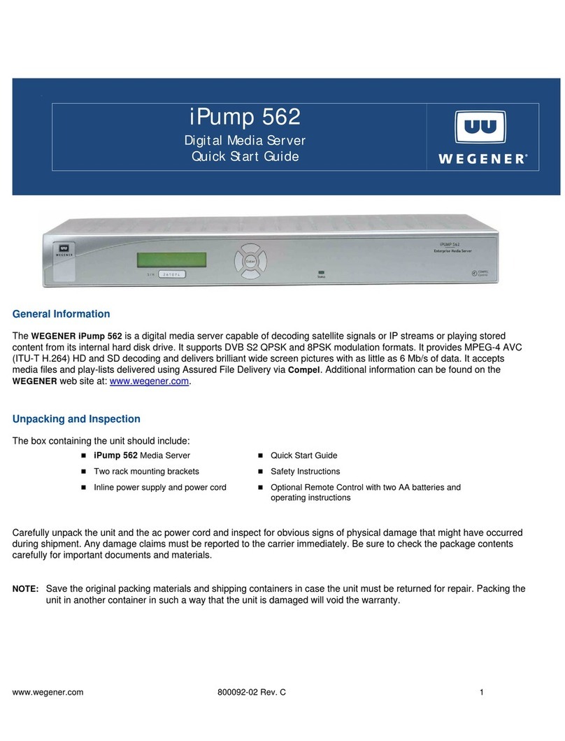
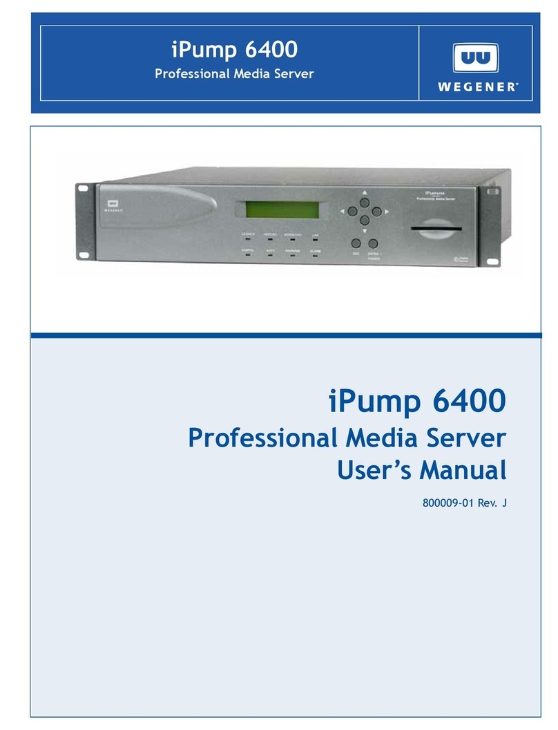
Wegener iPump User manual

iPump User’s Manual
800009-01 Rev. A 2 wegener.com
Data, drawings, and other material contained herein are proprietary to Wegener
Communications, Inc., and may not be reproduced or duplicated in any form
without the prior written permission of Wegener Communications, Inc.
The information contained herein is subject to change without notice.
Revisions may be issued to advise of such changes and/or additions.
Correspondence regarding this publication,
800009-01 Revision A
First Edition: November 2003
should be forwarded to:
Wegener Communications, Inc.
Technology Park/Johns Creek
11350 Technology Circle
Duluth, GA 30097-1502
Phone: 770-814-4000
Fax: 770-623-0698
COMPEL, MEDIAPLAN, ENVOY, UNITY, UNITY·IP and iPUMP are
trademarks of WEGENER Communications, Inc. All Rights Reserved.
All other trademarks are the property of their respective owners.
The Wegener iPumpTM is approved under FCC Part 15B Class A, UL1950,
CSA, and CE.

iPump User’s Manual
wegener.com 3 800009-01 Rev. A
Table of Contents
Chapter 1 General Information
1.1 Manual Overview . . . . . . . . . . . . . . . . . . . . . . . . . . . . . . . . . . . . . . . . 5
1.2 iPump Overview . . . . . . . . . . . . . . . . . . . . . . . . . . . . . . . . . . . . . . . . . 6
Physical Description . . . . . . . . . . . . . . . . . . . . . . . . . . . . . . . . . . . . . . 6
Functional Description . . . . . . . . . . . . . . . . . . . . . . . . . . . . . . . . . . . . 6
iPump Status Monitoring . . . . . . . . . . . . . . . . . . . . . . . . . . . . . . . . 6
Live Program Play . . . . . . . . . . . . . . . . . . . . . . . . . . . . . . . . . . . . . 6
Record Program to File. . . . . . . . . . . . . . . . . . . . . . . . . . . . . . . . . . 6
Play Recorded Program File . . . . . . . . . . . . . . . . . . . . . . . . . . . . . . 7
File Management . . . . . . . . . . . . . . . . . . . . . . . . . . . . . . . . . . . . . . 7
Playlists. . . . . . . . . . . . . . . . . . . . . . . . . . . . . . . . . . . . . . . . . . . . . . 7
Routing . . . . . . . . . . . . . . . . . . . . . . . . . . . . . . . . . . . . . . . . . . . . . . 7
Stream Creation . . . . . . . . . . . . . . . . . . . . . . . . . . . . . . . . . . . . . . . 7
Scheduled Operation. . . . . . . . . . . . . . . . . . . . . . . . . . . . . . . . . . . . 8
File Downloads . . . . . . . . . . . . . . . . . . . . . . . . . . . . . . . . . . . . . . . . 8
Files Served to LAN . . . . . . . . . . . . . . . . . . . . . . . . . . . . . . . . . . . . 9
Compel Control. . . . . . . . . . . . . . . . . . . . . . . . . . . . . . . . . . . . . . . . 9
HTML Control . . . . . . . . . . . . . . . . . . . . . . . . . . . . . . . . . . . . . . . . 9
Contact Closure/Alarms . . . . . . . . . . . . . . . . . . . . . . . . . . . . . . . . . 9
iPump Options . . . . . . . . . . . . . . . . . . . . . . . . . . . . . . . . . . . . . . . . . . . 9
Table 1iPump Options Key . . . . . . . . . . . . . . . . . . . . . . . . . . . . . . 10
1.3 iPump Specifications . . . . . . . . . . . . . . . . . . . . . . . . . . . . . . . . . . . . . 11
Table 2Technical Specifications. . . . . . . . . . . . . . . . . . . . . . . . . . . 11
1.4 Safety Summary. . . . . . . . . . . . . . . . . . . . . . . . . . . . . . . . . . . . . . . . . 13
1.5 Glossary of Terms and Abbreviations . . . . . . . . . . . . . . . . . . . . . . . . 13
Table 3Glossary of Terms. . . . . . . . . . . . . . . . . . . . . . . . . . . . . . . . 13
Chapter 2 Installation
2.1 Unpacking and Inspection . . . . . . . . . . . . . . . . . . . . . . . . . . . . . . . . . 15
2.2 Location and Mounting . . . . . . . . . . . . . . . . . . . . . . . . . . . . . . . . . . . 15
Rack Mounting . . . . . . . . . . . . . . . . . . . . . . . . . . . . . . . . . . . . . . . . . 17
Desktop Installation. . . . . . . . . . . . . . . . . . . . . . . . . . . . . . . . . . . . . . 17
2.3 iPump Connections . . . . . . . . . . . . . . . . . . . . . . . . . . . . . . . . . . . . . . 18
Table 4iPump Connector Details . . . . . . . . . . . . . . . . . . . . . . . . . . 19
Alarm Connector Details . . . . . . . . . . . . . . . . . . . . . . . . . . . . . . . . . . 19
Table 5iPump Alarm Connector Pin Functions . . . . . . . . . . . . . . 19
Ethernet/LAN Port Details . . . . . . . . . . . . . . . . . . . . . . . . . . . . . . . . 20
Table 6iPump LAN Connector Pin Functions . . . . . . . . . . . . . . . 20
Chapter 3 Operation
3.1 Operation Overview. . . . . . . . . . . . . . . . . . . . . . . . . . . . . . . . . . . . . . 21
3.2 Front-panel Controls and Indicators . . . . . . . . . . . . . . . . . . . . . . . . . 22

iPump User’s Manual
800009-01 Rev. A 4 wegener.com
Liquid-crystal Display(LCD) . . . . . . . . . . . . . . . . . . . . . . . . . . . . . . 22
Pushbuttons . . . . . . . . . . . . . . . . . . . . . . . . . . . . . . . . . . . . . . . . . . . . 22
LED Indicators . . . . . . . . . . . . . . . . . . . . . . . . . . . . . . . . . . . . . . . . . 23
Table 7LED Indicator Descriptions. . . . . . . . . . . . . . . . . . . . . . . . 23
3.3 Startup/Shutdown Procedures . . . . . . . . . . . . . . . . . . . . . . . . . . . . . . 25
Initial startup . . . . . . . . . . . . . . . . . . . . . . . . . . . . . . . . . . . . . . . . . . . 25
Normal Startup . . . . . . . . . . . . . . . . . . . . . . . . . . . . . . . . . . . . . . . . . 25
Web Browser Operations Startup . . . . . . . . . . . . . . . . . . . . . . . . . . . 26
Normal Shutdown . . . . . . . . . . . . . . . . . . . . . . . . . . . . . . . . . . . . . . . 27
3.4 Front-panel Operation . . . . . . . . . . . . . . . . . . . . . . . . . . . . . . . . . . . . 28
LCD Menu Navigation . . . . . . . . . . . . . . . . . . . . . . . . . . . . . . . . . . . 28
Editable Fields . . . . . . . . . . . . . . . . . . . . . . . . . . . . . . . . . . . . . . . . . . 29
Selectable Fields . . . . . . . . . . . . . . . . . . . . . . . . . . . . . . . . . . . . . . . . 30
3.5 Initial Unit Setup . . . . . . . . . . . . . . . . . . . . . . . . . . . . . . . . . . . . . . . . 31
Initial RF setup . . . . . . . . . . . . . . . . . . . . . . . . . . . . . . . . . . . . . . . . . 31
Table 8iPump Preconfigured RF Settings . . . . . . . . . . . . . . . . . . 31
Current Channel Setup. . . . . . . . . . . . . . . . . . . . . . . . . . . . . . . . . . . . 31
Date/Time Setup . . . . . . . . . . . . . . . . . . . . . . . . . . . . . . . . . . . . . . . . 33
Unit Label Setup . . . . . . . . . . . . . . . . . . . . . . . . . . . . . . . . . . . . . . . . 34
3.6 iPump Operations by Function . . . . . . . . . . . . . . . . . . . . . . . . . . . . . 36
Monitor iPump Status . . . . . . . . . . . . . . . . . . . . . . . . . . . . . . . . . . . . 36
Live Program Play . . . . . . . . . . . . . . . . . . . . . . . . . . . . . . . . . . . . . . . 37
Record Program to File . . . . . . . . . . . . . . . . . . . . . . . . . . . . . . . . . . . 40
Play Recorded Program File . . . . . . . . . . . . . . . . . . . . . . . . . . . . . . . 41
File Management . . . . . . . . . . . . . . . . . . . . . . . . . . . . . . . . . . . . . . . . 42
File Streaming and Routing. . . . . . . . . . . . . . . . . . . . . . . . . . . . . . . . 43
Scheduled Operation . . . . . . . . . . . . . . . . . . . . . . . . . . . . . . . . . . . . . 44
Playlist Management . . . . . . . . . . . . . . . . . . . . . . . . . . . . . . . . . . . . . 45
iPump Help . . . . . . . . . . . . . . . . . . . . . . . . . . . . . . . . . . . . . . . . . . . . 47
3.7 Unit Software Switch. . . . . . . . . . . . . . . . . . . . . . . . . . . . . . . . . . . . . 48
Chapter 4 Maintenance and Troubleshooting
4.1 Maintenance. . . . . . . . . . . . . . . . . . . . . . . . . . . . . . . . . . . . . . . . . . . . 49
4.2 Troubleshooting . . . . . . . . . . . . . . . . . . . . . . . . . . . . . . . . . . . . . . . . . 49
No functions at all . . . . . . . . . . . . . . . . . . . . . . . . . . . . . . . . . . . . . . . 49
No output . . . . . . . . . . . . . . . . . . . . . . . . . . . . . . . . . . . . . . . . . . . . . . 49
Trouble using browser interface . . . . . . . . . . . . . . . . . . . . . . . . . . . . 50
LED Indicators . . . . . . . . . . . . . . . . . . . . . . . . . . . . . . . . . . . . . . . . . 50
Table 9LED Indicator Descriptions. . . . . . . . . . . . . . . . . . . . . . . . 50
Chapter 5 Customer Service
5.1 Warranty . . . . . . . . . . . . . . . . . . . . . . . . . . . . . . . . . . . . . . . . . . . . . . 53
5.2 Technical Support . . . . . . . . . . . . . . . . . . . . . . . . . . . . . . . . . . . . . . . 53
Index
wegener.com 5 800009-01 Rev. A
Chapter 1 General Information
1.1 Manual Overview
This manual provides instructions and reference information for the proper
installation and operation of the Wegener iPump Media Server/Store and For-
ward Receiver, referred to throughout the manual as the iPump.
The manual is divided into the following chapters:
1 General Information - a description of your iPump, its functions and
specifications, and a glossary of terms.
2 Installation - procedures and information for the correct and safe instal-
lation of your iPump.
3 Operation - instructions on starting and operating your iPump.
4 Maintenance and Troubleshooting - information on maintaining your
iPump and resolving possible operating difficulties.
5 Customer Service - Our warranty and information on obtaining help.
An Index of keywords is also provided to help you quickly locate needed
information.
Please email any suggestions or comments concerning this manual to
manuals@wegener.com. If you prefer to post through the mail, please send
your comments to the address below. If you have substantial or complex
changes to recommend, our preference is that you copy the page(s) in question,
mark your changes on that copy, and fax or mail us the copy. We always
appreciate constructive criticism.
Our Address:
Attn: Manuals
Wegener Communications, Inc.
Technology Park / Johns Creek
11350 Technology Circle
Duluth, GA 30097-1502
Our Fax Number:(770) 497-0411

iPump User’s Manual
800009-01 Rev. A 6 wegener.com
1.2 iPump Overview
The Wegener iPump is an integrated, digital satellite receiver, decoder, and
media server designed to provide the most cost effective method of delivering
and storing digital content for broadcast, cable, and business operations. The
iPump is a key part of the Wegener Communications Digital Media Delivery
System which combines secure MPEG and IP digital transmission with media
management and server storage. At a given time, up to 260 hours of media
content can be stored on a single iPump (with optional, large disk capacity) and
served out via Ethernet according to current need or predetermined schedules.
With the iPump, you can receive, decode, and play out broadcast-quality trans-
missions while at the same time receiving from satellite and recording multiple
programs or IP data files. Combined with our Compel MediaPlan software, the
iPump can also place spot segments into real-time or recorded programs and
can schedule playback of custom sequences of live and recorded content.
Physical
Description
The iPump is housed in a standard, 2 RU, rack-mountable chassis. Its front
panel provides a user interface through an LCD and six pushbuttons (see Fig-
ure 3.1 iPump Front Panel on page 22). The rear panel holds the power
switch and the ports that allow connection to power, incoming signal, and
peripheral devices.
Functional
Description
Your iPump can perform the following functions:
iPump Status Monitoring
Front-panel and web browser interface screens allow real-time monitoring of
iPump activity, settings, and signal characteristics.
Live Program Play
The iPump decodes an incoming DVB MPEG program from the received sat-
ellite signal and decrypts and decodes the audio and/or video from the selected
program through analog or digital output ports to your monitor or transmission
equipment. The incoming content may be either a "classical" DVB program or
an IP multicast stream. RF and decoder settings are selected by the user. Two
live programs from the same DVB carrier may be played simultaneously by
iPumps which have the optional second decoder.
Record Program to File
The iPump can simultaneously record up to three separate multiplexed pro-
grams (either "classical" DVB or IP multicast stream) from the incoming
stream including any that are played live to the decoder(s). The user selects the
programs and enters a file name, audio setting, and a recording time (duration)
for each. Files are recorded to disk in the iPump for later play-out or download-

iPump User’s Manual
wegener.com 7 800009-01 Rev. A
ing. Up to 40 GB of storage (up to 43.3 hours of programming depending on
data rate) is available on standard iPumps and up to 240 GB on optional,
extended-storage iPumps (see Disk Storage Capacity).
Record and play functions can be used in such applications as "tape delay"/
time zone shifting, "spot" localization of commercials, and corporate training
media distribution.
Play Recorded Program File
The iPump plays out the selected, stored program files to the connected audio
and video monitors. File playing may be initiated by a predetermined schedule
via Compel or by a schedule stored internally to the iPump. The user may also
command playing of files directly from a web browser or from the front panel.
Two recorded programs (or one recorded and one live) may be played simulta-
neously on iPumps with an optional second decoder.
File Management
Compel users can rename or delete files stored on the iPump and organize
them into directories or folders. Renaming and deleting files may also be per-
formed through a web browser connected to the iPump over a LAN.
Playlists
Sequences of programs called Playlists can be created and stored on the iPump
by the user (locally or by COMPEL). Up to 100 Playlists can be stored in non-
volatile memory and played back with no interruption between programs. Set-
tings can be made to repeat the playlist indefinitely, complete the playlist and
repeat only the last program indefinitely, or complet the playlist and simply
return the decoder to its previous state.
Routing
The iPump can serve as a satellite-to-LAN IP router. Both unicast and multi-
cast IP traffic is supported. Multicast traffic can include, for example, MPEG
video streaming data. The IGMP protocol is followed for multicast traffic.
Stream Creation
The iPump can create IP multicast video streams and present them on the LAN
for use by other equipment. The source of the video stream may be either a pre-
recorded or downloaded file or a "classical" DVB program.

iPump User’s Manual
800009-01 Rev. A 8 wegener.com
The iPump can also multicast previously-stored streams to the LAN. See Fig-
ure 1.1 iPump Routing for an illustration of iPump routing paths.
Figure 1.1 iPump Routing
Scheduled Operation
Schedules of record, play, and other operations for automatic execution by the
iPump may be set up using the Compel network and may be viewed from the
web browser interface. (Schedule operations support wild cards and ranges in
day, date, and time fields for repetitive events.)
File Downloads
The iPump accepts files downloaded from the satellite link via Compel’s
Assured File Delivery package. Application software and other files may also
be downloaded. Up to five downloads may be performed simultaneously up to
an aggregate data rate of 25 Mbps.
The iPump's file download and record functions may be used to load the unit
with content for playout (according to a pre-arranged schedule if desired) at
any time. This can be particularly useful in applications with extended or con-
tinuous playout needs and limited satellite operating times.

iPump User’s Manual
wegener.com 9 800009-01 Rev. A
Files Served to LAN
Users sharing a LAN with the iPump may download stored files from the
iPump to their local workstation or server using FTP or SMB protocol.
Compel Control
iPump operation may be controlled remotely by a Compel network. Compel
Conditional Access controls which iPumps may access the satellite’s material
and prevents access by any other receive equipment. Local control of the unit
may be disabled for exclusive control by Compel. The iPump always follows
the most recent command received and does not prioritize commands based on
origination from the front panel, web browser interface, or Compel network.
HTML Control
Control of the iPump is available from any web browser on the LAN to which
it is connected or via the internet if desired. The IP address and subnet mask
can be displayed and changed at the iPump front panel.
Contact Closure/Alarms
The iPump provides a contact closure through a rear-panel connector whenever
the unit enters an alarm condition. An additional user relay is also available.
The iPump can also sense a contact closure input. Using Compel, file playouts
can be triggered by local closure of this input.
iPump
Options
The iPump Media Server/Store and Forward Receiver is available in several
configurations to meet specific applications. Input type, decoder type, disk
storage capacity, Conditional Access, and the presence of a second decoder can
be varied to create models best suited for your specific needs.

iPump User’s Manual
800009-01 Rev. A 10 wegener.com
The iPump model number is structured as follows to describe the options on
each iPump:
IP - ABC - D - EF - G - H - JJ - K
Table 1: iPump Options Key
Model Number
Position Option Name Designator Description
IP This prefix simply indicates that the unit is an iPump.
A Input Type 1 - DVB RF Input
2 - ASI Input
B First Decoder Type
(middle slot)
0 - No decoder
1 - Basic decoder
2 - professional 4:2:0 decoder with analog outputs
3 - professional 4:2:2 decoder with analog outputs
4 - professional 4:2:2 decoder with digital outputs
5 - professional audio output
C Second Decoder Type
(bottom slot)
0 - No second decoder
1 - Basic decoder
2 - professional 4:2:0 decoder with analog outputs
3 - professional 4:2:2 decoder with analog outputs
4 - professional 4:2:2 decoder with digital outputs
5 - professional audio output
D Disk Storage Capacity 1 - 40 Gigabytes
2 - 80 Gigabytes
3 - 120 Gigabytes
4 - 160 Gigabytes
5 - 200 Gigabytes
6 - 240 Gigabytes
E Contact Closure Module
Type
1 - Alarm and contact closure in and out on DB-9
2 - Alarm and contact closure in and out on DB-9, plus
RJ-11 internal modem
F Reserved
G Reserved
HLineCord
(power connector)
1 - U.S.
2 - U.K.
3 - Europe
4 - Australia
JJ Reserved
K Other 0 - none
1 - Auxiliary audio

iPump User’s Manual
wegener.com 11 800009-01 Rev. A
1.3 iPump Specifications
Table 2: Technical Specifications
Characteristic Specification
RF
Input Frequency tuning via front panel control or COMPEL
Input FrequencyRange 950 to 2150 MHz
Input Impedance 75 ohms
LNB Power 250 mA max, 22 kHz tone control
vertical polarity: 12.4 to 14.0 VDC
horizontal polarity: 17.0 to 19.0 VDC
Tuning Resolution 1 kHz
Modulation QPSK
Transport Rate Range 2.0 to 45 Msps
VIDEO COMPRESSION
Video Data Rate up to 15 Mbps per service
Compression Type MPEG 4:2:0 or 4:2:2
Horizontal Resolution 720, 704, 640, 544, 480, 352
Vertical Resolution 480 lines @ 30 Hz (NTSC)
240 lines @ 30 Hz (NTSC)
576 lines @ 25 Hz (PAL)
288 lines @ 25 Hz (PAL)
VIDEO OUTPUT
Video Format NTSC/PAL composite and SDI (with embedded audio)
Output Level 1 Vpp ± 5%
Output Impedance 75 ohms
AUDIO COMPRESSION
Compression Type MPEG Layer II
Data Rate 64 to 384 kbps
Output Modes Supported Mono, Dual Mono, Joint Stereo

iPump User’s Manual
800009-01 Rev. A 12 wegener.com
AUDIO OUTPUT
Frequency Response 20 Hz to 20 kHz
GENERAL
Power Supply 100 to 120 V or 200 to 240 V (auto switches)
60/50 Hz
5.0/2.5 A
Size
height 3.5 inches (90 mm)
width 19 inches (483 mm)
[17 inches (432 mm) with mounting ears removed]
depth 16"(406 mm)
ENVIROMENTAL
Use Indoor only
Operating Temperature +10° C to +40° C
Altitude Less than 2000 meters
Humidity Maximum relative humidity of 80% for temperatures up
to 31° C decreasing linearly to 50% relative humidity at
40° C.
Table 2: Technical Specifications
Characteristic Specification

iPump User’s Manual
wegener.com 13 800009-01 Rev. A
1.4 Safety Summary
The iPump is designed for safe use with few special precautions required of the
user. The following items are basic precautions to use when installing and
working with your iPump:
Do not open the iPump's chassis cover.
1.5 Glossary of Terms and Abbreviations
Table 3: Glossary of Terms
Term Definition
AC Alternating current
Alarm A condition or notification of a condition that prevents your iPump from performing
properly.
AFD Assured File Delivery.
Authorized Describes an iPump which has the ability through Compel Conditional Access to
decrypt programs encrypted by the Compel software.
Carrier An RF signal containing coded audio, video, and/or other data.
CompelTM Wegener's network control software that may be used to manage a number of iPumps
and other hardware.
Conditional Access The means by which Compel controls which iPumps may decrypt specially encrypted
audio, video, or data streams.
DVB Digital Video Broadcast
EIA Electronic Industries Association
Ethernet The widely-used LAN technology specified by IEEE standard 802.3
FTP File transfer protocol
GB Gigabyte or 230 bytes
IEEE Institute of Electrical and Electronics Engineers
LAN Local area network. Your iPump may be connected to an Ethernet LAN.

iPump User’s Manual
800009-01 Rev. A 14 wegener.com
LCD Liquid crystal display. The front-panel text screen on your iPump is a liquid crystal dis-
play.
LED Light-emitting diode. The front-panel indicator lights on your iPump are LEDs
LNB Low-noise block downconverter - equipment (generally at the antenna) that converts
the incoming satellite signal to the appropriate frequency for reception by the iPump.
Mbps, kbps or
Msps
Units of data transport rate - Megabits per second (1 million bits per second), kilobits
per second (1 thousand bits per second), or million symbols per second (1 milion sym-
bols per second)
MPEG Moving Picture Experts Group - refers to the method of video compression established
by this group.
Program A single media stream (audio, video, data, etc.) tied to a common time base.
Program Number A numerical code representing a program.
RF Radio frequency
SMB Server message block - a protocol for requesting services from and reading and writing
to a file server.
TMRA Maximum Recommended Ambient Temperature, the highest operating temperature for
which the unit is rated
Warning A condition or notification of a condition that may compromise the proper performance
of your iPump
Table 3: Glossary of Terms
Term Definition

wegener.com 15 800009-01 Rev. A
Chapter 2 Installation
This chapter provides instructions on unpacking, mounting, and connecting
your iPump as well as connector information including detailed pinouts.
2.1 Unpacking and Inspection
Carefully unpack the unit and its ac power cord and inspect for obvious signs
of physical damage that might have occurred during shipment. Also locate the
bag of accessories including 1/8-to-RCA and SVD-to-RCA adapters. Any
damage claims must be reported to the carrier immediately. Be sure to check
the package contents carefully for important documents and materials.
NOTE: Please save the packing materials and original shipping containers in
case you must later return the unit for repair. Packing these units in other
containers in such a way that they are damaged will void your warranty.
2.2 Location and Mounting
The iPump may be mounted in a standard 19-inch equipment rack or fitted
with rubber feet for desk top operation. In either location, maintain a clean, dry
environment for your iPump.
WARNING
This is a Class A product. In a domestic environment this product may cause
radio interference for which the user may need to take mitigating action.

iPump User’s Manual
800009-01 Rev. A 16 wegener.com
DANGER
To avoid damage to this and other equipment, or personal injury, the following
items should be strictly observed.
Elevated Operating Ambient
When equipment is installed in a closed or multi-unit rack assembly, the
operating ambient of the rack environment may be greater than the room
ambient. Therefore, consideration should be given to the ambient air
temperature within the rack, and not just inside the room, when deciding if the
maximum recommended ambient operating temperature (TMRA) is being met.
Reduced Air Flow
Equipment should be installed such that airflow required for safe operation of
the equipment is not compromised. The iPump may be arranged in a rack
without empty spaces between units if heat rise is prevented by ensuring its
side vents remain unblocked with adequate clearance around the vent holes.
Mechanical Loading
Mounting of the equipment in a rack should be such that a hazardous
condition is not produced by uneven loading. This unit is not very heavy, but
total rack loading must be considered. Also, do not rest any unsupported
equipment on your iPump.
Circuit Overloading
Consideration should be given to the connection of the equipment to the
supply circuit and the effect that overloading of circuits could have on
overcurrent protection and supply wiring. Ensure that the total rack or breaker
power consumption does not exceed the limits of the ac branch circuit.
Appropriate consideration of equipment ratings should be used when
addressing this concern.
Reliable Earthing
Reliable earthing of rack-mounted equipment should be maintained. Particular
attention should be given to supply connections other than direct connections
to the branch circuit (use of power strips, chassis ground lugs, etc.).

iPump User’s Manual
wegener.com 17 800009-01 Rev. A
Rack
Mounting
Your iPump is sized at 2 RU and will fit an EIA-standard, 19-inch-wide equip-
ment rack (See “Size” on page 12.).
a) First install angle brackets or cross-supports capable of supporting both
the unit and its connecting cables. Screw or bolt the supports securely
to the equipment rack.
b) Place the iPump on its supports and use four anchor screws or bolts and
nuts to secure the iPump's front brackets to the rack.
WARNING
The front brackets must be secured to the rack. If front brackets are left
unsecured, the unit may shift forward and fall from the rack during installation
or operation. Failure to secure the front brackets may result in personal injury
and/or damage to the equipment.
Desktop
Installation
To set up the iPump in a desktop environment, first attach the self-adhesive
mounting feet supplied with your unit. Peel of the backing and press one to the
bottom of the chassis near each corner.
Place the iPump on a flat surface where it will not be subject to spills or
impacts. Also route cables to the unit so that they will not be hit or pulled caus-
ing damage to the connectors or to the unit itself. Ensure a sufficient flow of
cool air (See “Reduced Air Flow” on page 16.) so that the unit's operating
ambient temperature range is not exceeded.
WARNING
Locate the iPump and its cables to avoid impacts, spills, and pulling cables
and to ensure sufficient air flow. Failure to locate the iPump in a proper
environment may result in damage to the equipment.

iPump User’s Manual
800009-01 Rev. A 18 wegener.com
2.3 iPump Connections
Before applying power, make the following connections to your iPump (refer
to Table 4 on page 19 for connector details and to Figure 2.1 iPump Rear-
panel Connector Locations for placement):
a) Connect the L-band output from your antenna's LNB to the extender
cable on your iPump's input RF port [a]. (A BNC connector is used
here for iPumps with the ASI input option.)
b) Connect a suitable audio monitor or monitors to the iPump's audio
port(s) [b1] (on both decoders if your iPump includes a second
decoder). Also connect audio monitoring to the auxiliary audio port
[b2] if your iPump includes that option (See Table 1: iPump Options
Key on page 10).
c) Connect a suitable video monitor or monitors to the iPump's video [c]
port (on both decoders if your iPump includes a second decoder). (See
Table 1: iPump Options Key on page 10).
d) Connect your LAN line to the iPump's Ethernet port [d]. (Refer to
Table 6: iPump LAN Connector Pin Functions on page 20.)
Figure 2.1 iPump Rear-panel Connector Locations
e) If desired, connect the Alarm port [e] to your equipment to provide
contact closures and openings during alarms or on command from
Compel. (Refer to Table 5: iPump Alarm Connector Pin Functions
on page 19.)
f) Finally, connect the supplied ac power cord to the iPump's IEC
receptacle [f] and to a 100-to-120 Vac or 200-to-240 Vac source.
NOTE: Do not connect devices to the mouse, keyboard and other connectors
not described here. They are for factory use only.

iPump User’s Manual
wegener.com 19 800009-01 Rev. A
Alarm
Connector
Details
The DB-9 alarm connector has the following pin functions:
Table 4: iPump Connector Details
Designation Connector
Type Signal Description Additional Information
RF IN female Type F 950 to 2150 MHz RF carrier
from antenna LNB
A extension cable is shipped already
attached to the RF IN port to allow
easier access for attaching your RF
input.
ASI IN female BNC ASI input signal Only on iPumps with the ASI input
option.
AUDIO 1/8-inch stereo
jack
Audio output A 1/8-to-RCA adapter is shipped
with your iPump (one for each active
audio decoder).
AUX AUDIO 1/8-inch stereo
jack
Audio output Can be "slaved" to decoder 1 or
decoder 2
VIDEO BNC S-video, video output A SVD-to-RCA adapter is shipped
with your iPump. Units equipped
with the optional, professional 4:2:2
decoders will have a female BNC
connector.
LAN female RJ-45 10/100baseT Ethernet Autosensing; see pinout detail
inTable 6: iPump LAN Con-
nector Pin Functions on
page 20
CONTACT
CLOSURE/
ALARM
male DB-9 Contact closure/opening in and
out
See pinout detail inTable 5:
iPump Alarm Connector Pin
Functions on page 19
POWER Male IEC recep-
tacle
100-to-120 Vac @60 Hz or
200-to-240 Vac @ 50 Hz
Autoswitching
Table 5: iPump Alarm Connector Pin Functions
Pin Number Function
1 Alarm common
2 Alarm Normally Open
3 Contact Closure Out Common
4 No Connection
5 Contact Closure Input

iPump User’s Manual
800009-01 Rev. A 20 wegener.com
The DB-9 female alarm connector on the rear panel provides contact closures
and openings during alarm conditions as well as a user relay available for con-
trol by Compel command (USER CC). Normal conditions represent the con-
tact in normally functioning, powered operation. Other conditions or
commands will reverse the status of the contact from its normal position.
Pins 1 and 2 are normally open and are closed during an iPump alarm.
Pins 1 and 6 are normally closed and are open during an iPump alarm.
Pins 3 and 8 on the DB-9 are normally open and may be closed by command
from Compel.
Pin 5 is the local, user input (0=trigger).
Ethernet/
LAN Port
Details
The iPump's 10/100baseT (autosensing) Ethernet port has the following pin
functions:
6 Alarm Normally Closed
7 No Connection
8 Contact Closure Out Normally Open
9 Ground
Table 5: iPump Alarm Connector Pin Functions
Pin Number Function
Table 6: iPump LAN Connector Pin Functions
Pin Number Name Description
1 TX_D1+ Transmit Data+
2 TX_D1- Transmit Data-
3 RX_D2+ Receive Data+
4 Unused
5 Unused
6 RX_D2- Receive Data-
7 Unused
8 Unused
Other manuals for iPump
1
Table of contents
Other Wegener Server manuals

Wegener
Wegener i6420 User manual

Wegener
Wegener iPump 562 User manual

Wegener
Wegener iPUMP6400 User manual

Wegener
Wegener iPump 562 User manual

Wegener
Wegener iPUMP 6400 User manual

Wegener
Wegener iPUMP 6400 User manual

Wegener
Wegener iPump 6420 User manual

Wegener
Wegener iPump 562 User manual

Wegener
Wegener iPump 622 Datasheet
Popular Server manuals by other brands

Xantech
Xantech Digital Music Server XMusic user guide

Lenovo
Lenovo ThinkServer RD530 Garanti och support

Oracle
Oracle StorageTek 8 Gb FC PCIe HBA installation guide

disguise
disguise solo Hardware guide

HPE
HPE ProLiant DL360 Gen11 Maintenance and service guide

HP
HP t5630 - Thin Client Quick reference guide