WEGOMA DF550 User manual

DF550
DF550
Dichtungsnutfräse
Fresadora ranuradora
Grooving machine
Fraiseuse à rainures
Modell · Modelo · Model · Modèle
1796119
GEBRAUCHSANWEISUNG
MANUALDEINSTRUCCIONES
OPERATING INSTRUCTIONS
MODE D' EMPLOI
E
GB
F
D
DF550
10/2000
WEISSHOLZMASCHINENGmbH&COKG
ImGrund13•D-75045Walzbachtal-Jöhlingen•Germany
Fon(07203)9210-0•Fax(07203)9210-200
www.wegoma-holz.de•E-mail:[email protected]

2
DF550
9
4
8
6
5
7
3
2
1
DEUTSCH Dichtungsnutfräse DF550 5
ESPAÑOL Fresadora ranuradora DF550 6
ENGLISH DF550 Grooving machine 8
FRANÇAIS Fraiseuse à rainures DF550 9
seite/página
page
Fig. 1
GEBRAUCHSANWEISUNG
MANUAL DE INSTRUCCIONES
OPERATING INSTRUCTIONS
MODE D'EMPLOI
11

3
A
B
C
D
D
C
E
F
H
G
Fig. 2
Fig. 3
Fig. 4
Fig. 5
Fig. 6
Fig. 7
10
du centreur F, commandé par le bouton E, (Fig. 6).
Pour commencer une rainure, appuyer à fond sur le
boutonE,etplacerlamachinesurl'élémentàrainurer,
appuyée entre la partie postérieure du guidage et
l'extrémité du centreur F. Ensuite et après avoir mis
en marche la machine, il faut lâcher peu à peu le
bouton E, jusqu'à ce que la fraise entre dans le bois
et que le guidage de la machine soit totalement
appuyé, on pourra alors commencer à avancer.
Pour le fraisage de rainures dans l'encadrement, et
afindepouvoirarriverjusqu'auxcoins,oncommencera
le rainurage à un point intermédiaire de la huisserie
ouducroisillon,onferalarainurejusqu'àuneextrémité
et il faudra répéter l'opération en partant du même
point de départ, vers l'autre extrémité.
5.1 FRAISAGES AVEC GUIDAGE 90° (Fig. 11)
Onemploieraceguidage,pourlefraisagederainures
obliquesà45°,surledélardementdesencadrements,
ou sur les fenêtres.
5.2 FRAISAGES AVEC GUIDAGE
DROIT (Figs. 12 y 13)
Il permet de réaliser des rainures droites, dans le
délardement des encadrements ou sur les fenêtres.
Il est possible de faire le rainurage de fenêtres, sans
avoir à démonter les partie fixes. (Fig. 12).
A l'aide de l'équerre (Fig. 13), on peut réaliser des
rainures dans des zones lisses, comme le côté des
gonds sur une porte, à une distance réglable en
partant d'une face.
6. REMPLACEMENT DES GUIDAGES
Leremplacementduguidage,(Figs.2et3),seréalise
très facilement, en enlevant la vis B qui le fixe, et en
letirantvers l'arrière commelemontrela (Fig. 3)pour
le faire sortir.
Lenouveauguidagesemonteradelamêmemanière.
En remplaçant le guidage, la profondeur de fraisage
se maintient, c'est pourquoi il n'est généralement pas
nécessairedefaireunnouveauréglagedelamachine.
7. MONTAGE DE L'ÉQUERRE RÉVERSIBLE
Il est possible d'utiliser l'équerre réversible sur les
deux côtés de la machine. Pour son montage, il faut
extrairelesdeuxécrousC,(Fig.4).Introduirel'équerre
dans les orifices latéraux de la machine et la fixer
danslaposition souhaitée,enla fixant contrelecorps
de la machine entre les écrous C et D, (Fig. 5).
8. REMPLACEMENT DE LA FRAISE
ATTENTION. Débrancher la machine du secteur,
avant de réaliser cette opération.
Pourremplacerlafraise (Fig. 7), bloquerl'axemoteur
à l'aide de la clé H, dévisser l'écrou avec la clé G et
extraire la fraise. Introduire la nouvelle fraise en
faisantensorte qu'il yait43 mm, ±1mm,entre la face
de l'écrou et la pointe de la fraise et revisser l'écrou
à l'aide de la clé.
Les fraises fournies par WEGOMA, sont aiguisées
aux deux extrémités.
9.RÉGLAGEDELAPROFONDEURDEFRAISAGE
Desserrer la vis K, (Fig. 8), jusqu'à ce qu'on puisse
fairebougerlemoteuraveclesmains.Ensuitetourner
l'excentriqueIaveclaclé de service, jusqu'à ce qu'on
obtienne la mesure souhaitée à l'aide de la jauge J.
Quand on a obtenu la mesure souhaitée, revisser la
vis K.
10. JOINTS
Il est conseillé d'utiliser les joints en caoutchouc de
silicone, pour leur excellente résistance aux
intempériesetleurpropriétésélastiquessouscharge,
à des températures entre -60° C et 200° C.
11. ENTRETIEN DE BALAIS ET COLLECTEUR
ATTENTION. Débrancher la machine du secteur,
avant d'effectuer toute opération d'entretien.
Enlever les vis L du couvercle, en retirant celui-ci, les
balais apparaîtront dans leurs logements (Figs. 9, 10).
Enlever les ressorts M qui font pression et les
remplacer par d'autres d'origine WEGOMA, en
s'assurantqu'ilsglissentbienàl'intérieurdesguidages.
Remonter comme il est indiqué ci-dessus. Il est
recommandédemettreenmarchelamachinependant
15 minutes après avoir changé les balais.
Silecollecteurprésentedesbrûluresoudesressauts,
il est recommandé de le faire réparer par un service
technique WEGOMA.
Conserver le câble et la prise dans de bonnes
conditions de service.
12. GARANTIE
Toutes les machines électro-portatives WEGOMA
ont une garantie valable 12 mois à partir du jour de la
fourniture, en étant exclus toutes manipulations ou
dommages causés par des maniements inadéquats
ou par usure naturelle de la machine.
Pour toute réparation, s'adresser au service officiel
d'assistance technique WEGOMA.
WEGOMAseréserveledroitdemodifiersesproduits
sans avis préalable.

4
52 mm.
max.
J
K
IM
L
Fig. 8
Fig. 9 Fig.10
Fig.11 Fig.12 Fig.13
Fig.
14
9
To change the miller (Fig. 7) block the motor shaft
using key H, unscrew the bolt with the key G and
remove the bit. Insert the new miller until its tip is
within 43 ± 1mm from the face of the bolt and re-
tighten this using the key.
The bits supplied by WEGOMA are sharpened at
both ends.
9. CONTROLLING THE DEPTH OF THE GROOVE
Loosen screw K (Fig. 8) until the motor can be moved
by hand. Next turn the eccentric I with the service key
until the required measurement is obtained with the
help of the gauge J. When obtained re-tighten bolt K.
10. JOINTS
The use of SILICON RUBBER JOINTS is
recommendedfortheirhighresistancetobadweather
and elasticity under load at temperatures between -
60° C and 200° C.
11. MAINTENANCE OF THE
BRUSHES AND COLLECTOR
WARNING!Disconnectfromthemainsbeforecarrying
out any maintenance operations.
RemovescrewsLandremovethecover.Thebrushes
will appear in their place (Figs. 9 and 10).
Lift the springs M which hold them down and replace
them with new WEGOMA original spares, ensuring
that they move smoothly inside the guides.
Remount as indicated above. We recommend you
keep the machine running for 15 minutes once the
brushes have been changed.
If the collector is burned or uneven it should be
repaired by a WEGOMA service agent.
Always keep the lead and plug in good working
condition.
12. GUARANTEE
All of WEGOMA portable electrical goods are
guaranteed for 12 months from the date of supply,
excluding any damage which is a result of incorrect
use or of natural wear and tear on the machine.
All repairs should be carried out by the official
WEGOMA technical assistance service.
WEGOMA reserves the right to modify its products
without prior notice.
FRAISEUSE À RAINURES DF550
1. INSTRUCTIONS DE SÉCURITÉ POUR LE
MANIEMENT DE LA FRAISEUSE A RAINURES
1. ATTENTION! Lire attentivement la BROCHURE
D'INSTRUCTIONS GÉNÉRALES DE SÉCURITÉ,
jointe à la documentation de la machine.
2. Avant de brancher la machine, s'assurer que la
tension d'alimentation correspond à celle indiquée
sur la plaque des caractéristiques.
3. Maintenir toujours les mains éloignées de la zone
de coupe, et prendre toujours la machine par les
poignées.
4. Utiliser toujours des outils d'origine WEGOMA. Ne
jamaisutiliserd'outils défectueux ou en mauvaisétat.
5. Il est necessaire de travailler avec l'aspiration de
poussière pour éviter que la fraise se casse.
2. CARACTÉRISTIQUES TECHNIQUES
Puissance absorbée........................................550 W
Moteur..........................................................50/60Hz
Niveau de pression acoustique
continu équivalent pondéré......................84.4 dB (A)
Niveau habituel vibrations (main-bras)........<2,5 m/s2
Révolutions...............................................30000/min
Pinceporte-fraise...........................................Ø6mm
Poidsmachine...................................................1,9kg
Dimensionsd’emballage.............................(370x420)
3. ÉQUIPEMENT STANDARD
Al'intérieurdelamallettedetransport,voustrouverez
les éléments suivants (Fig. 1):
1.- Fraiseuse à rainures DF550 avec fraise carbure
aiguisée aux deux pointes.
2.- Guidage 90°.
3.- Guidage droit.
4.- Équerre réversible.
5.- Jauge de profondeur.
6.- Clé o/c: 11 mm pour axe moteur.
7.- Clé o/c: 19 mm pour écrou fixation pince.
8.- Clé allen o/c: 3 mm.
9.- Tube aspiration.
4. DESCRIPTION GÉNÉRALE
DE LA FRAISEUSE DF550
La machine a pour fonction principale le rainurage de
fenêtres et portes, pour la mise en place de joints
isolants.
Lamachineestéquipée de 2 types deguidageetune
équerre réversible qui permettent de réaliser des
rainures dans diverses positions comme il est expli-
qué dans les paragraphes suivants de ce manuel.
Elle dispose également d'un pivot de centrage, qui
facilite l'entrée de la fraise au début de l'opération. La
machineestéquipée d'une prised'aspiration,où peut
être branché, moyennant LE TUBE
D'ACCOUPLEMENT D'ASPIRATEUR à n'importe
quel type d'aspirateur industriel.
5. TYPES DE FRAISAGE
Les rainures peuvent être réalisées sur les parties
mobiles des portes ou fenêtres, ainsi que sur
l'encadrement, il est plus recommandé de le faire sur
l'encadrement car cela résulte plus facile.
Pour contrôler l'entrée de la fraise dans le bois, d'une
manière progressive et centrée, la machine dispose
FRANÇAIS

5
DICHTUNGSNUTFRÄSE DF550
1. SICHERHEITSHINWEISE FÜR DIE
BEDIENUNG DER NUTENFRÄSMASCHINE
1. ACHTUNG! Lesen Sie bitte aufmerksam die
BROSCHÜRE ÜBER ALLGEMEINE
SICHERHEITSHINWEISE, die Sie zusammen mit
den Unterlagen der Maschine erhalten haben.
2. Bevor Sie die Maschine einschalten, versichern
Sie sich, daß die Versorgungsspannung der auf dem
Typenschild angegebenen entspricht.
3. Bringen Sie Ihre Hände nie in die Nähe der
Schnittfläche und halten Sie die Maschine immer an
den Griffen fest.
4. Verwenden Sie immer Original-WEGOMA-
Werkzeuge. Verwenden Sie nie fehlerhafte
Werkzeuge oder solche, die in einem schlechten
Zustand sind.
5. Um die Lebensdauer der Fräser zu verlängern und
zu verhindern, dass sie möglicherweise brechen,
muss mit Spanabsaugung gearbeitet werden.
2. TECHNISCHE DATEN
Leistungsaufnahme......................................550 W
Motor..........................................................50/60 Hz
Umgerechnetes akustisches Dauer-
druckpegeläquivalent..............................84,4 dB(A)
Normaler Schwingungspegel(Hand-Arm)<2,5 m/s2
Umdrehungen......................................30.000/min
Fräsenhalterung..........................................Ø 6 mm
Gewicht der Maschine...................................1,9 kg
Abmessungen der Verpackung................(370 x 420)
3. STANDARDAUSRÜSTUNG
Im Transportkoffer finden Sie folgende Teile (Abb.
1. Nutenfräsmaschine DF550 mit HM-Fräser 3mm
beidseitig verwendbar.
- 90°-Führung
- Gerade Führung
- Umkehrbarer Winkel
- Tiefenlehre
- Schlüssel 11 mm, für die Motorachse
- Schlüssel 19 mm, für die Spannzange
- Imbus-Schraubenschlüssel 3mm.
- Absaugungschlauch.
4. ALLGEMEINE BESCHREIBUNG
DER FRÄSMASCHINE DF550
Die Maschine ist in erster Linie für das Fräsen von
Nuten in Fenstern und Türen zum Einsetzen von
Isolierdichtungen gedacht.
Sie ist mit 2 verschiedenen Führungen und einem
umkehrbarenWinkelausgestattet,sodaß,wie in den
folgenden Abschnitten dieser Betriebsanweisung
erklärt, in verschiedenen Positionen Nuten gefräst
werden können. Sie verfügt ebenfalls über einen
Zentrierstift, der das Einstechen der Fräse zu Beginn
der Arbeit erleichtert.
Die Maschine hat einen Absaugungsanschluß, an
dem jeder beliebige Industriesauger angebracht
werden kann.
5. FRÄSARTEN
Die Nuten können sowohl in den beweglichen Teilen,
wie Türen oder Fenster, oder im Rahmen gezogen
werden. Letzteres ist einfacher und daher zu
empfehlen.Damit derFräserlangsamundzentriert in
das Holz eindringt, ist die Maschine mit dem
Zentrierstift D ausgerüstet, der mit dem Knopf E
betätigt wird (Abb.6).
Am Anfang einer Nut drückt man den Knopf E ganz
durch, hält die Maschine über das zu fräsende Teil
und stützt sie dabei zwischen dem hinteren Teil der
Führung und dem Ende des Zentrierstifts D ab.
Nachdem dem Einschalten der Maschine, läßt man
den Knopf E langsam los bis der Fräser in das Holz
eingedrungenist unddieFührung derMaschineganz
aufliegt. Jetzt kann gefräst werden.
Damit man beim Nutenfräsen im Rahmen bis in die
Ecken kommt, beginnt man an einem mittleren Punkt
im Rahmen oder Querbalken, zieht die Nut bis zu
einem Ende durch und wiederholt den gleichen
Vorgang vom selben Ausgangspunkt ausgehend bis
zum anderen Ende.
5.1 FRÄSEN MIT DER 90°-FÜHRUNG (Abb. 11)
DieseFührung wirdfür dasFräsen vonschrägen 45°-
NutenimFalzderRahmenoderinFensterneingesetzt.
5.2 FRÄSEN MIT DER GERADEN
FÜHRUNG (Abbs. 12 und 13)
Ermöglicht das Ziehen von geraden Nuten im Falz
von Rahmen oder Fenstern.
Nuten in Fenstern können gezogen werden, ohne die
feststehenden Teile herauszunehmen. (Abb. 12).
Mit dem in der (Abb. 13) gezeigten Winkel können in
glatten Bereichen wie auf der Seite von Türbändern
Nuten gezogen werden. Dabei ist der Abstand von
einer Seite einstellbar.
6. AUSWECHSELN DER FÜHRUNGEN
Die Führung ist leicht zu wechseln (Abb. 2 und 3),
indem man einfach die Schraube B löst, die die
Führung festhält. Dann zieht man sie wie in (Abb. 3)
gezeigt nach hinten heraus.
Die neue Führung wird entsprechend eingesetzt.
Beim Auswechseln der Führung wird die Frästiefe
nicht verändert, so daß normalerweise keine
Neueinstellung des Werkzeuges notwendig ist.
7. ANBRINGEN DES UMKEHRBAREN WINKELS
Der umkehrbare Winkel kann an beiden Seiten der
Maschine verwendet werden. Um ihn anzubringen,
löst man die beiden Muttern C (Abb. 4). Den Winkel
durchdieseitlichenÖffnungenderMaschineeinsetzen
DEUTSCH
8
productos sin previo aviso.
DF550 GROOVING MACHINE
1. SAFETY INSTRUCTIONS FOR
USE OF THE GROOVING MACHINE
1.WARNING!ReadcarefullytheGENERALSAFETY
INSTRUCTIONS LEAFLET, which is included in the
machine documentation.
2. Before starting up the machine make sure that the
supply voltage is the same as that shown on the
specification plate.
3. Always keep hands clear of the cutting area, and
always hold the machine using the grips.
4. Always use original WEGOMA tools. Never use
damaged tools or tools in poor condition.
5.It'sadvisableto work with dustcollectionin order to
avoid the bit's break.
2. TECHNICAL CHARACTERISTICS
ImputPower.......................................................550W
Motor.............................................................50/60Hz
Equivalent measured
acousticpressurelevel.............................84.4dB (A)
Normal level of vibrations (hand-arm).........<2,5 m/s2
Noloadspeed...........................................30,000/min
Chuckcollet.....................................................Ø6mm
Weight...............................................................1.9kg
Packingdimensions....................................(370x420)
3. STANDARD EQUIPMENT
Contained in the transportation case you will find the
following elements (Fig. 1):
1.- Grooving machine DF550 with carbide bit
sharpened at both ends.
2.- 90° guide.
3.- Straight guide.
4.- Reversible angle.
5.- Depth gauge.
6.- Size 11 mm key for motor shaft
7.- Size 19 mm key for securing clamp.
8.- Size 3 mm Allen key.
9.- Dust collection pipe
4. GENERAL DESCRIPTION
OF THE DF550 GROOVING MACHINE
The main function of the machine is to make grooves
and windows in doors for inserting isolation seals.
The machine is equipped with 2 kinds of guide and a
reversibleanglethat enable the making ofgrooves in
variouspositionsasexplainedinthefollowingsections
of this manual. It also has a centering pivot which
facilitates the entry of the bit at the start of the
operation.
The machine is also equipped with a suction nozzle
which can be used for connection to any industrial
dust collector via the dust collector connection pipe
No. 9 (Fig. 1).
5. TYPES OF GROOVING
The grooves can be made in the moveable parts of
doors and windows as well as in the frames, which is
recommended for its simplicity. To control the gra-
dual, centered entry of the miller in the wood the
machine has a centering attachment F which is
activated using button E, (Fig. 6).
To begin a groove button E is pressed to the bottom,
and the machine is placed over the piece to be
grooved, supported by the rear part of the guide and
the end of the centering attachment F. Next, after
startingupthemachine,buttonEisgraduallyreleased
untilthemiller is introduced inthewood and theguide
is completely supported, at which time we can begin
moving forward.
In making the groove in the frame in order to reach
into the corners begin grooving at an intermediate
point on the frame or crosspiece. Make the groove to
one end then repeat the operation from the same
starting point working towards the other end.
5.1 GROOVES WITH 90° GUIDE (Fig. 11)
This guide is used for making grooves angled at 45°
in the cut-outs of frames or in windows.
5.2 GROOVES WITH STRAIGHT GUIDE (Fig. 12
and 13)
Used for making straight grooves in the cut-outs of
frames or in windows.
It is possible to groove windows without having to
dismantle the fixed ones. (Fig. 12).
Using the angle, (Fig. 13), grooves can be made on
smooth areas such as the side of the hinges on the
door at a distance which can be adjusted from one
side.
6. CHANGING THE GUIDES
Changing the guide (Figs. 2 and 3) is easily carried
out by removing screw B which holds it in place and
pulling it back as shown in (Fig. 3) until it has been
removed.
The new guide is inserted in the same way.
On changing the guide, the depth of the groove is
maintained, which means that re-adjustment of the
tool is not usually required.
7. MOUNTING THE REVERSIBLE ANGLE
Thereversibleangle canbeused for bothsidesof the
machine. For its assembly the 2 screws C must be
removed, (Fig. 4). Insert the reversible angle in the
side openings on the machine and secure it where
desired by supporting it against the body of the
machine between screws C and D. (Fig. 5).
8. CHANGING THE BIT
WARNING! Disconnect the machine from the mains
before carrying out this operation.
ENGLISH

6
und in der gewünschten Position befestigen. Halten
Sie ihn dabei zwischen den Muttern C und D gegen
den Maschinenkörper (Abb. 5).
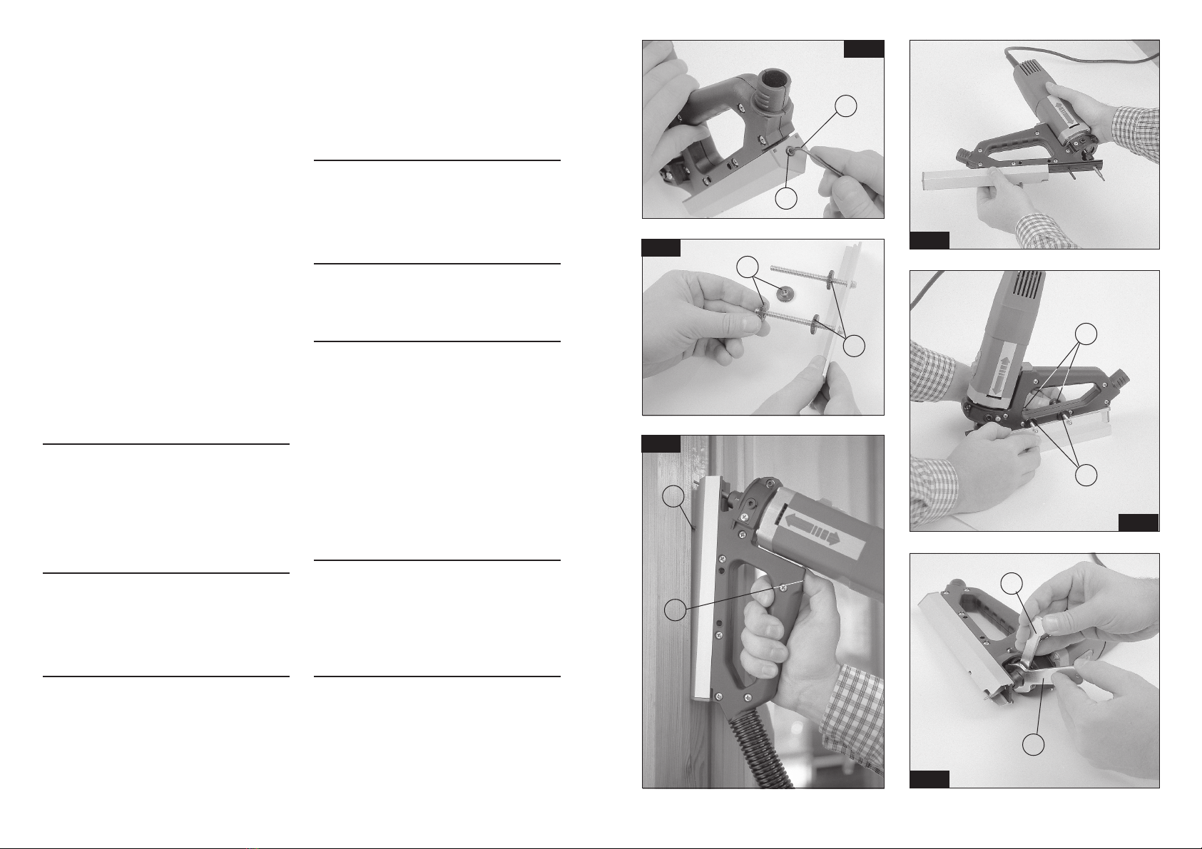
8. AUSWECHSELN DES FRÄSERS
ACHTUNG!VordieserArbeitdenNetzsteckerziehen.
Zum Auswechseln des Fräsers (Abb. 7) die
Motorachse mit dem Schlüssel H blockieren, die
Mutter mit dem Schlüssel G losschrauben und den
Fräserherausziehen.DenneuenFräsersoeinsetzen,
daß sich ihre Spitze 43 ± 1 mm von der Vorderseite
der Mutter entfernt befindet. Die Mutter mit Hilfe der
Schlüssel erneut anziehen. Die von WEGOMA
gelieferten Fräser sind beidseitig verwendbar,
sowieleichtgedrilltumeineoptimaleSpäneabfuhr
zu gewährleisten.
9. EINSTELLUNG DER FRÄSTIEFE
DieSchraubeKlockern(Abb.8)bisderMotormitden
Händen bewegt werden kann. Dann den Exzenter I
mit dem Bedienungsschlüssel drehen bis mit Hilfe
derLehreJdasgewünschte Maßeingestelltist.Dann
die Schraube K wieder festziehen.
10. DICHTUNGEN
Wegen ihrer hervorragenden Wetterbeständigkeit
und ihrer elastischen Eigenschaften unter Belastung
bei Temperaturen von -60° C bis 200° C empfehlen
wir den Einsatz von Silikonkautschukdichtungen.
11. WARTUNG DER BÜRSTEN
UND DES SCHLEIFRINGS
ACHTUNG! Ziehen Sie vor allen Wartungsarbeiten
den Netzstecker.
Wenn Sie die Schrauben L aus der Kappe lösen und
die Kappe abnehmen, sehen Sie die Bürsten in ihren
Lagerungen (Abb. 9, 10).
Heben Sie die Federn M an und ersetzen Sie die
Bürsten durch Original WEGOMA-Teile. Stellen Sie
sicher, daß sie leicht in den Führungen gleiten.
Setzen Sie alles wie oben beschrieben wieder
zusammen. Nach dem Auswechseln der Bürsten
sollte man die Maschine ca. 15 Minuten lang laufen
lassen.
Sollte der Schleifring Brandspuren oder
abgesprungene Stellen aufweisen, lassen Sie ihn
beim WEGOMA-Kundendienst reparieren.
Sorgen Sie immer für einen guten Betriebszustand
von Kabel und Stecker.
12. GARANTIE
Alle tragbaren Elektrogeräte von WEGOMA haben
eine Garantie von 24 Monaten ab dem Lieferdatum.
Hiervon ausgeschlossen sind alle Eingriffe oder
Schäden aufgrund von unsachgemäßem Gebrauch
oder natürlicher Abnutzung des Geräts.
Wenden Sie sich im Falle einer Reparatur immer an
den zugelassenen Kundendienst von WEGOMA.
WEGOMA behält sich das Recht vor, die Produkte
ohne vorherige Ankündigung zu verändern.
FRESADORA RANURADORA DF550
1. INSTRUCCIONES DE SEGURIDAD
PARA EL MANEJO DE LA RANURADORA
1. ¡ATENCIÓN! Lea atentamente el FOLLETO DE
INSTRUCCIONES GENERALES DE SEGURIDAD,
que se adjunta con la documentación de la máquina.
2. Asegúrese antes de enchufar la máquina, que la
tensión de alimentación se corresponda con la indi-
cada en la chapa características.
3. Mantenga siempre las manos alejadas del área de
corte,y sujetesiempre lamáquina porlas empuñaduras.
4. Use siempre herramientas originales WEGOMA.
No use nunca herramientas defectuosas o en mal
estado.
5. Es necesario trabajar con aspiración de la viruta
para prolongar la vida de la fresa y evitar posibles
roturas de la misma.
2. CARACTERÍSTICAS TÉCNICAS
Potenciaabsorbida..........................................550W
Motor.............................................................50/60Hz
Nivel de presión acústica
continuo equivalente ponderado..............84.4 dB (A)
Nivel vibraciones habitual (mano-brazo).....<2,5m/s2
Revoluciones.............................................30.000/min
Pinzafresa.......................................................Ø6mm
Pesomáquina...................................................1,9Kg
Dimensionesdeembalaje...........................(370x420)
3. EQUIPO ESTÁNDARD
En el interior de la maleta de transporte, Ud. encon-
trará los elementos siguientes (Fig.1):
1.- Fresadora ranuradora DF550 con fresa M.D.
afilada en ambas puntas.
2.- Guía 90°.
3.- Guía recta.
4.- Escuadra reversible.
5.- Galga de profundidad.
6.- Llave e/c: 11 mm. para eje motor.
7.- Llave e/c: 19 mm. para Tuerca fijación pinza.
8.- Llave allen e/c: 3 mm.
9.- Tubo aspiración
4. DESCRIPCIÓN GENERAL
DE LA FRESADORA DF550
La función principal de la máquina es el ranurado de
ventanas y puertas, para la colocación de juntas de
aislamiento. La máquina va equipada con 2 tipos de
guía y una escuadra reversible que permiten realizar
ranuras en diversas posiciones como se explica en
los próximos apartados de este manual. Dispone
también, de un pivote de centraje, que facilita la
ESPAÑOL
7
entrada de la fresa al principio de la operación. La
máquina va provista de toma para aspiración, por la
que puede conectarse, mediante el TUBO ACOPLA-
MIENTO ASPIRADOR No. 9 (Fig. 1) a cualquier
aspirador industrial.
5. TIPOS DE FRESADO
Las ranuras pueden realizarse tanto en las partes
móviles; puertas, o ventanas, como en el marco,
donde es más recomendable por su sencillez.
Para controlar la entrada de la fresa en la madera, de
un modo progresivo y centrado, la máquina dispone
del centrador F, que es accionado por el botón E.
(Fig. 6).
Para empezar una ranura, se presionará a fondo el
botón E, y se colocará la máquina sobre el elemento
a ranurar, apoyada entre la parte posterior de la guía
y el extremo del centrador F. A continuación y tras la
puesta en marcha de la máquina, soltaremos progre-
sivamente el botón E, hasta que la fresa se introduz-
ca en la madera, y la guía de la máquina quede
totalmente apoyada, momento en que podremos
iniciar el avance. En el fresado de ranuras en el
marco, y a fin de poder llegar hasta las esquinas, se
iniciará el ranurado en un punto intermedio del bas-
tidor o travesaño, se ranurará hasta un extremo y
deberá repetirse la operación desde el mismo punto
de inicio, hacia el otro extremo.
5.1 FRESADOS CON GUÍA 90° (Fig. 11)
Se empleará esta guía, para el fresado de ranuras
oblicuas a 45°, en el rebajo de los marcos, o en las
ventanas .
5.2 FRESADOS CON GUÍA RECTA (Fig. 12 y 13)
Permite la realización de ranuras rectas, en el rebajo
de los marcos o en las ventanas .
Esposible el ranuradode ventanas,sinnecesidad de
desmontar las fijas. (Fig. 12).
Con la ayuda de la escuadra (Fig. 13), pueden
realizarse ranuras en zonas lisas, como el lateral de
los pernios en una puerta, a una distancia regulable
desde una cara.
6. CAMBIO DE GUÍAS
El cambio de la guía, (Figs. 2 y 3), se realiza muy
fácilmente, con sólo extraer el tornillo B, que la sujeta
y tirar de ella hacia atrás como muestra la (Fig. 3)
hasta su extracción. La nueva guía se montará de
modo análogo.
Al cambiar de guía, se mantiene la profundidad de
fresado, por lo que no suele ser necesario una nueva
regulación de la herramienta.
7. MONTAJE DE LA ESCUADRA REVERSIBLE
La escuadra reversible puede utilizarse por ambos
ladosdelamáquina.Para sumontaje,debenextraer-
selasdos tuercasC,(Fig. 4), insertarlaescuadra por
los orificios laterales de la máquina, y fijarla en la
posicióndeseada,sujetándose contra elcuerpode la
máquina, entre las tuercas C y D, (Fig. 5).
8. CAMBIO DE FRESA
ATENCIÓN.Desconectela máquinadela redeléctri-
ca, antes de realizar esta operación. Para el cambio
de la fresa (Fig. 7), bloquee el eje motor mediante la
llave H, desenrosque la tuerca con la llave G y
extraigalafresa.Introduzcalanuevafresa,hastaque
la punta de la misma, quede a 43 ±1 mm., de la cara
de la tuerca y apriete esta de nuevo con la ayuda de
la llaves.
Las fresas suministradas por WEGOMA, están afila-
das por ambos extremos.
9. REGULACIÓN DE LA
PROFUNDIDAD DE FRESADO
Aflojar el tornillo K (Fig. 8), hasta que el motor pueda
moverse con las manos. Seguidamente girar la ex-
céntrica I con la llave de servicio, hasta conseguir la
medidadeseadaconlaayudade la galga J y una vez
obtenida esta, apretar de nuevo el tornillo K.
10. JUNTAS
Seaconsejaelempleo de JUNTAS DE CAUCHO DE
SILICONA,por suexcelenteresistenciaala intempe-
rie y sus propiedades elásticas bajo carga, a tempe-
raturas entre -60°C y 200°C.
11. MANTENIMIENTO DE
ESCOBILLAS Y COLECTOR
ATENCIÓN.Desconectela máquinadela redeléctri-
ca, antes de efectuar cualquier operación de mante-
nimiento.
Quitar los tornillos L del capuchón, separar éste, y
apareceránlasescobillasensusalojamientos(Figs.9,10).
LevantarlosresortesMquelas presionan y reempla-
zarlas por otras originales WEGOMA, asegurándose
que deslizan suavemente en el interior de las guías.
Volver a montar como se ha indicado anteriormente.
Es aconsejable que se tenga en marcha durante
unos 15 minutos la máquina una vez cambiadas las
escobillas.
Si el colector presenta quemaduras o resaltes, se
recomienda hacerlo reparar en un servicio técnico
WEGOMA.
Mantenga siempre el cable y el enchufe en buenas
condiciones de servicio.
12. GARANTÍA
Todas las máquinas electroportátiles WEGOMA tie-
nen una garantía válida de 12 meses a partir del día
de su suministro, quedando excluidas todas las ma-
nipulaciones o daños ocasionados por manejos in-
adecuados o por desgaste natural de la máquina.
Para cualquier reparación dirigirse al servicio oficial
de asistencia técnica WEGOMA.
WEGOMA se reserva el derecho de modificar sus
Table of contents
Other WEGOMA Power Tools manuals
Popular Power Tools manuals by other brands

RED ROOSTER
RED ROOSTER RRI-50S manual

Worcraft PROFESSIONAL
Worcraft PROFESSIONAL CD-S20LiE instruction manual

Brown Products
Brown Products Trench Master R450H Owner's/operator's manual

Wacker Neuson
Wacker Neuson EH 27/115 Operator's manual

Atlas Copco
Atlas Copco ETV STB63-70-13-IRC-W Product instructions

DeWalt
DeWalt DC490 instruction manual